Alien V-SYSTEM Manual

Designed, manufactured and distributed by
set up instructions
1
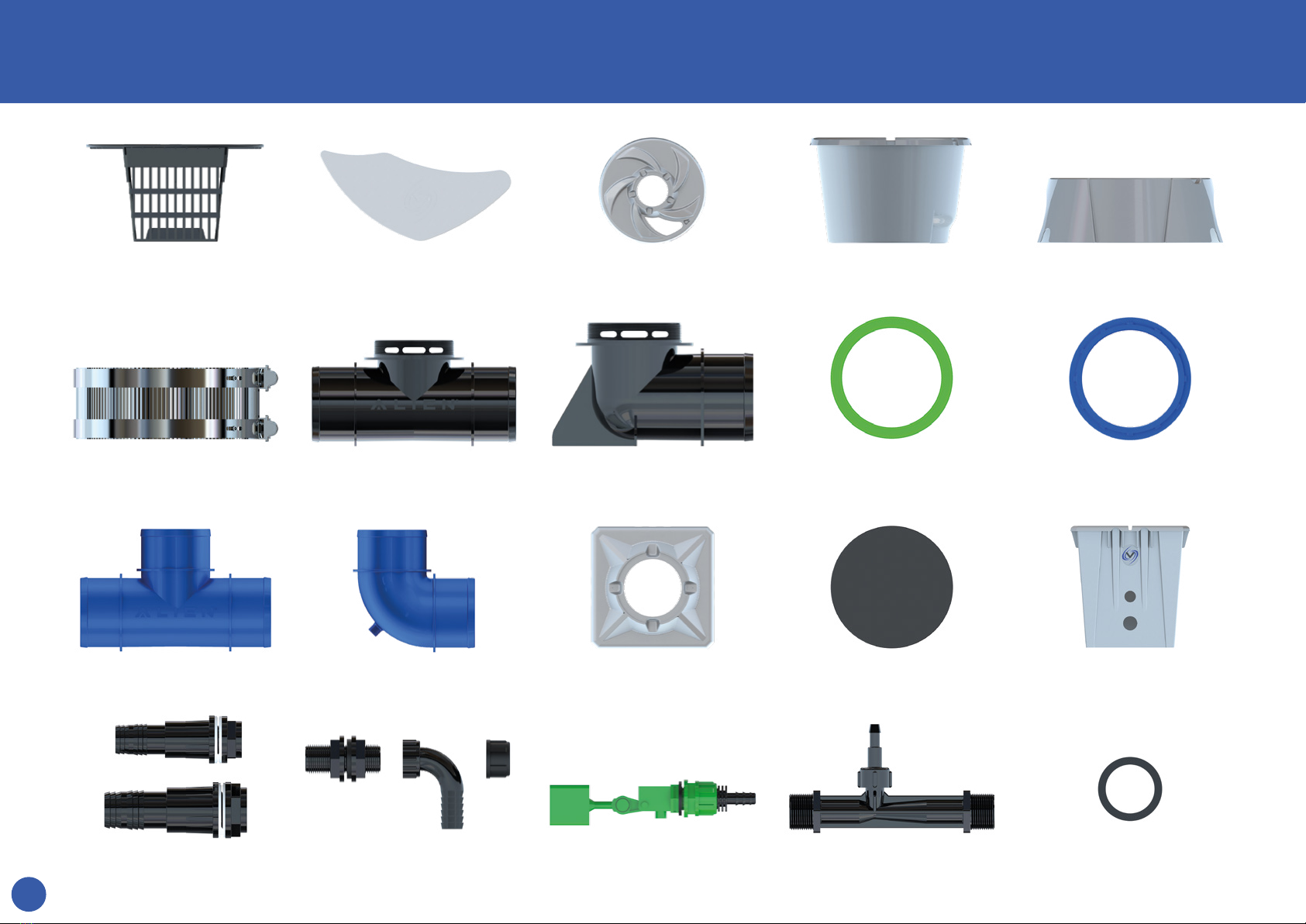
Part Descriptions
Net Pot Lid cover Lid V-POT Base
5 Inch Clamp Dual-Flow Tee Dual-Flow Elbow 5” Silicone Washer 5” Nut
5” Tee 5” Elbow Header Lid Header Blank Header Pot
32mm, 40mm Tank
connectors.
Chiller Fittings Float Valve Venturi Venturi Washer 3/4”
2
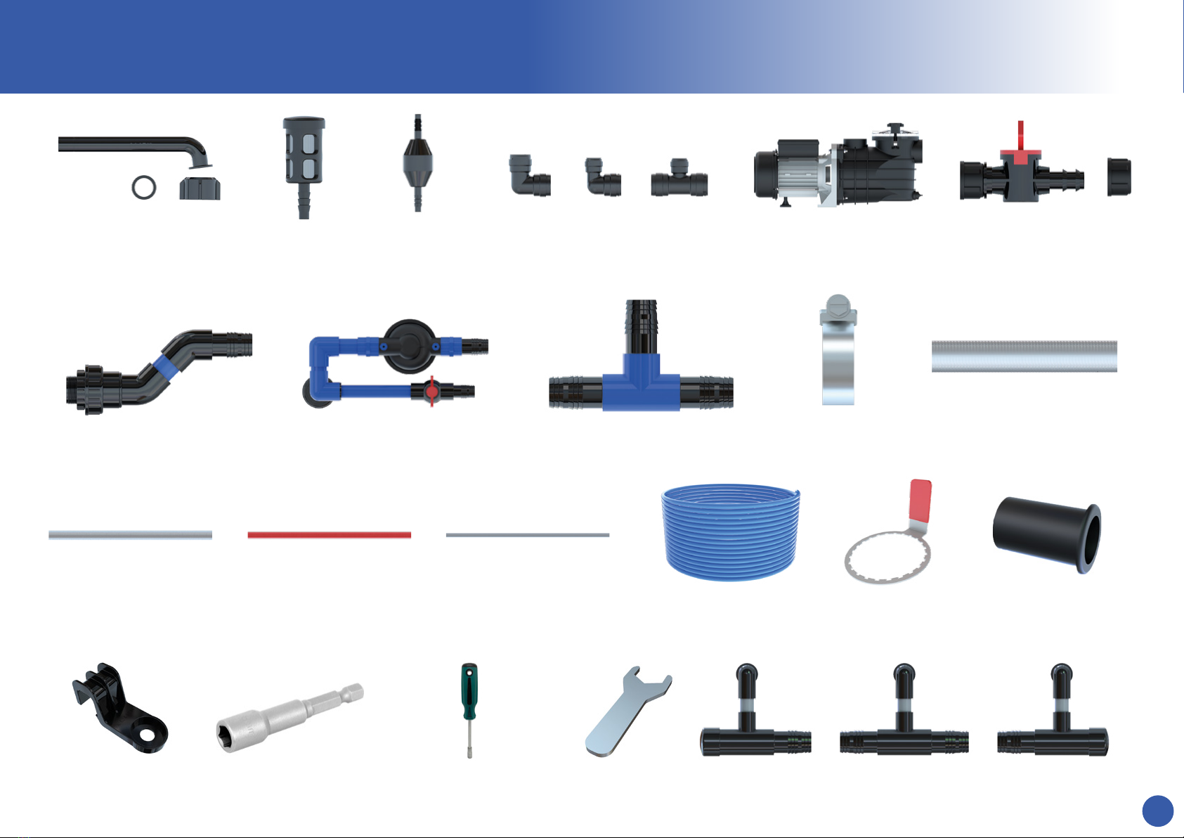
Inlet Tube, Wing
Nut, Washer
Air Filter Silencer Push-Fit Connectors, Elbow,
Reducing Elbow, Tee
Vortex Pump
Inlet Manifold Filter Manifold Distribution Tee Jubilee Clip 5” Tube 80cm
40mm Tube 1m 32mm Tube 22mm Barrier Pipe 6mm Blue Pipe
8mm socket 8mm Screwdriver Spanner Left Terminal Centre Terminal Right Terminal
5” Spanner Insert
Drain Tap & Cap
Pot Clip
3
INSTRUCTION MANUAL
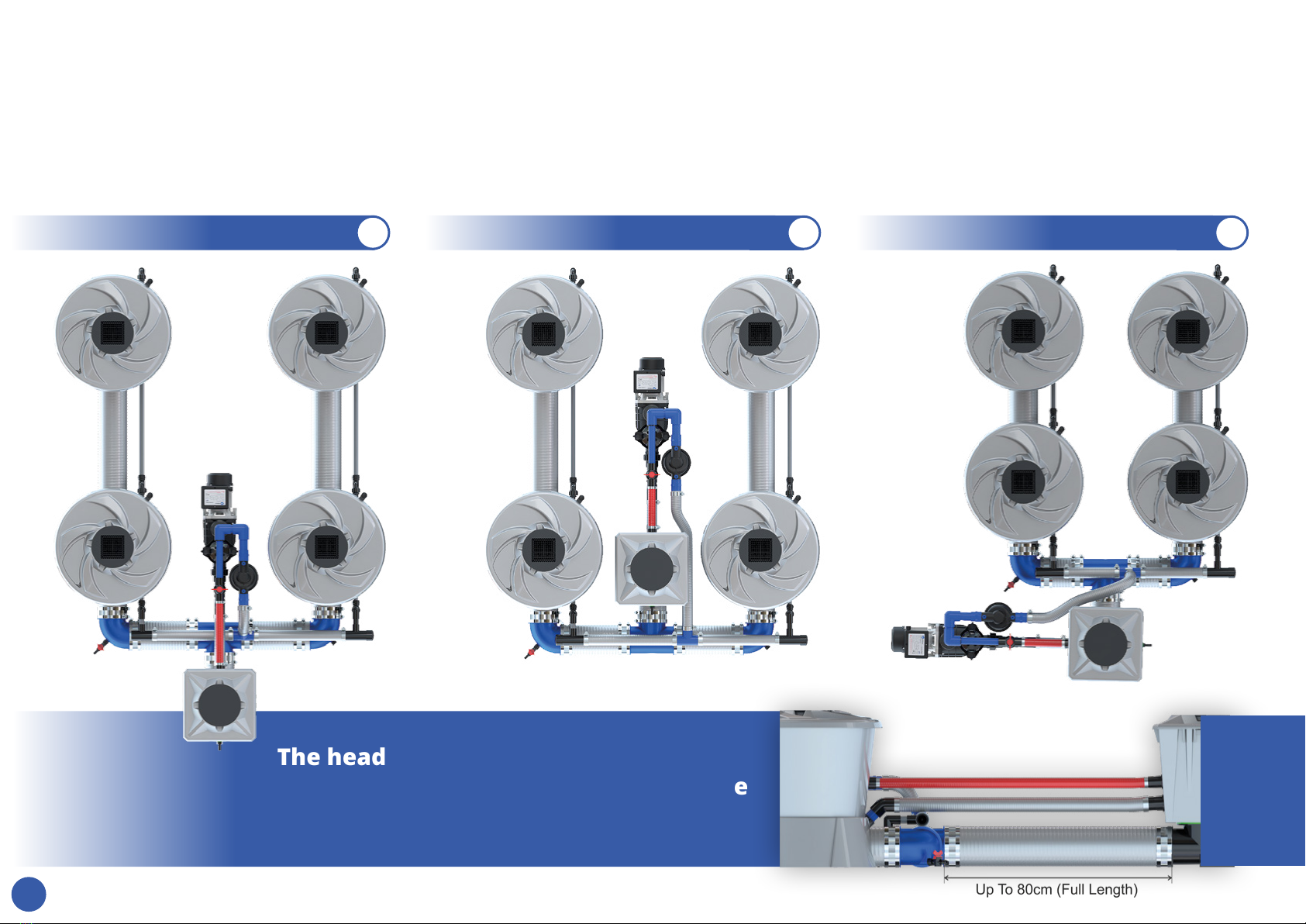
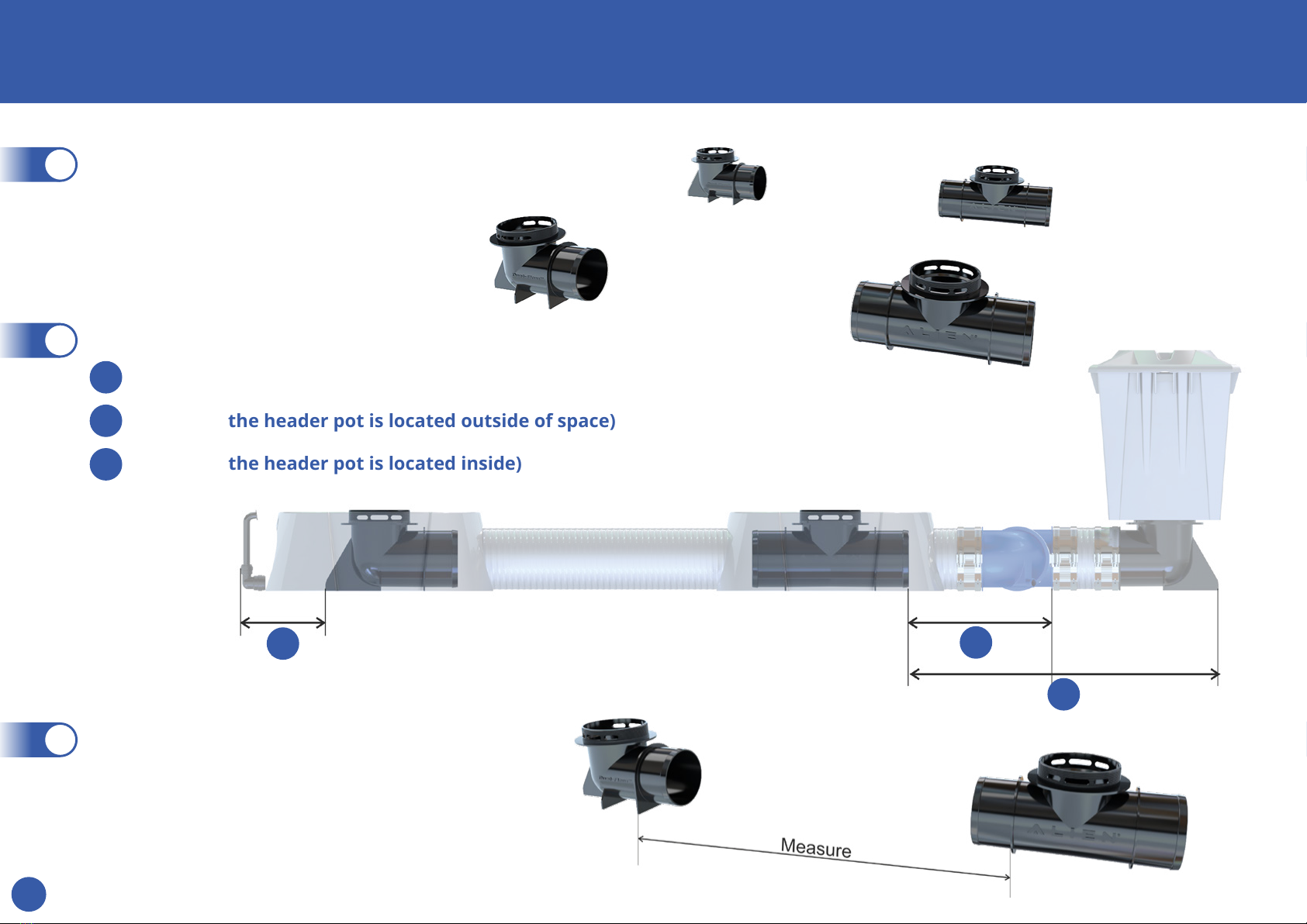
Before you begin the installation of the ALIEN®V-SYSTEM, consider the plant spacings which best suit your grow room layout.
The V-SYSTEM uses spiral tubing which gives the grower some versatility on the layout and header pot position. The standard conguration is shown
in Fg 1 with the header outside of the footprint. Fg 2 is with the header inside and requires 100cm centres to allow the header pot to t between the
pots. 65cm plant centres require Fg 3 conguration. The maximum centres with the supplied pipe are 100cm and a full length of 80cm pipe is used to
achieve this. Larger plant centres are possible with special order lengths of 5” pipe.
1Fg 2Fg 3Fg
The header pot can be extended away
from the system. For example to locate
the header outside of a grow tent
4
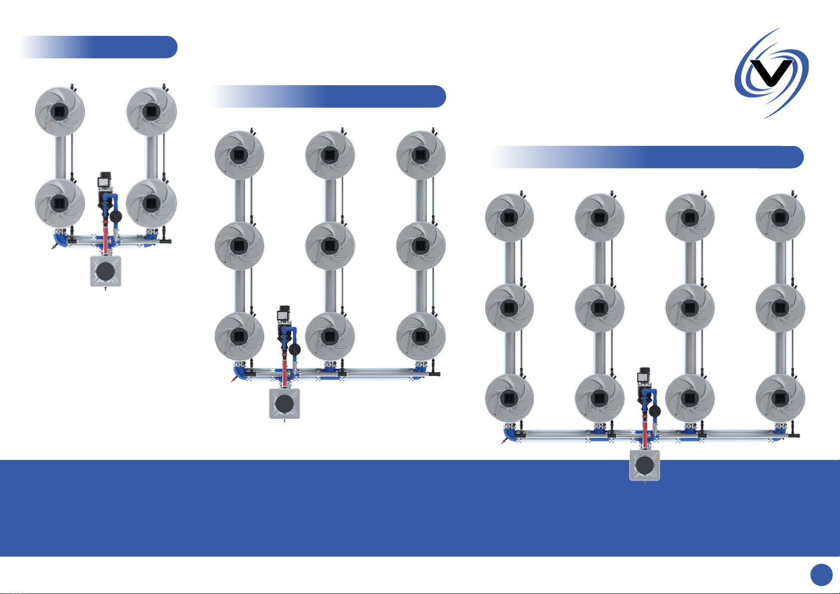
2 row
3 row
4 row
Configurations
5 rows + set ups are possible. Contact our tech team for advice.
5
Position the black Dual-Flow tee’s & elbows
where you would like the plants to be.
1
Once you are condent that the system will
t in the space measure the distance between
the anges and cut the 5” pipe using the pipe
cutters. (Take care as the blade is very sharp)
3
Minimum distance from obstacles:
2
A190mm
B315mm (If the header pot is located outside of space)
C700mm (If the header pot is located inside)
AB
C
SYSTEM SET-UP

6
Slide a 5” clamp over the pipe. Use hot soapy water
to warm the pipe then push on to the tting all the
way to the ange. Use the 8mm socket screwdriver
or electric drill attachment to tighten the clamp.
(ensure the nuts are located to the side as shown)
4
2 row
3 row 4 row
8mm socket 8mm
Screwdriver
7
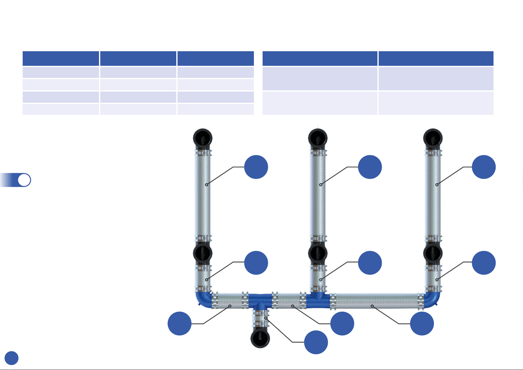
Tube 75cm 100cm
A 55cm 80cm
B 23cm 23cm
C 20cm 32cm
D 55cm 80cm
Header tube E
Minimum 15cm
Maximum 80cm
This table shows the tube lengths for the most common plant centres.
AAA
BBB
C C D
E
Pipe Length Guide
Position the blue 5” ttings to
make the manifold. The drain
outlets on the elbows should be
at the bottom. Once you’re sure
the system spacings are correct,
cut and t the 5” tube.
5
If you are using either a 4 pot
system in a 1.5x1.5m tent or a 16
pot system in a 3x3m tent reduce
the plant center’s marked ‘A’
from 75cm to 70cm to allow space
for the manifold.

8
Position the stands as
shown and place a green
washer on each tting.
6
Ensure the air inlet on each Venturi
is tightened. The rubber washer goes
on the outside of the pot. The long
side points towards the pot. There is
an arrow on the side of the Venturi
to show the direction of ow.
The system will
not work with the
Venturi’s installed
the wrong way
around. Use the
spanner provided
to tighten the nut
on the inside.
7
Venturi Installation
Spanner

9
Put the pots on the stands using
the locating hole in the base.
8
Screw the blue 5” nuts on and
tighten with the spanner Provided.
9
Table of contents
Popular Irrigation System manuals by other brands

Hunter
Hunter Institutional Series instructions

Cellfast
Cellfast 52-305 user manual

Tyco Fire Product
Tyco Fire Product Star Galaxy SGQR instruction manual

Tyco Fire Product
Tyco Fire Product CENTRAL A instruction manual

Oral Care Technologies
Oral Care Technologies Hydro Floss Instructions for use

Reliable
Reliable F1-300 quick start guide


