manuals.online logo
Brands
  1. Home
  2. •
  3. Brands
  4. •
  5. Align
  6. •
  7. Toy
  8. •
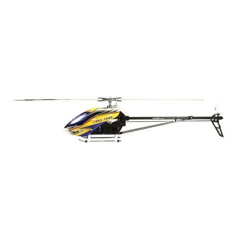
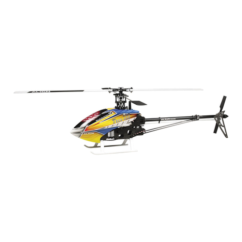
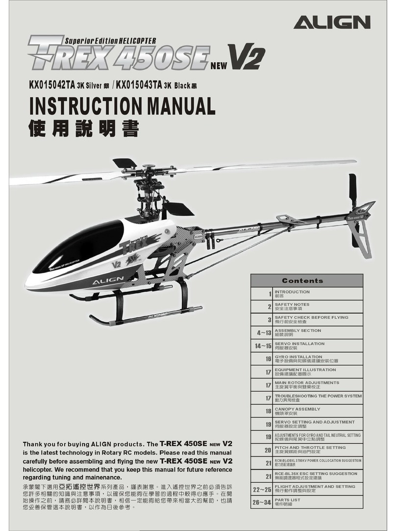
  9. Align TREX 700E V2 User manual

Align TREX 700E V2 User manual

f'
TREX
7iiifiV2
INSTIUCTIIN MINUll
•••••
KX018E12T
1
INTRODUCTION
ftOg
1-2
3
EQUIPMENT REQUIRED FOR ASSEMBLY
I3t1U :flL
3
PACKAGE ILLUSTRATION
m~~~
4SAFETY CHECK BEFORE FLYING
mBlrtI~~lfHi
5-17
ASSEMBLY SECTION
m~~~
18
EQUIPMENT INSTALLATION
§JftNfiiIi BI l
19
BATTERY INSTALLATION ILLUSTRATION
.It l~~7.jUilill
20
INSTALLATION FOR ESC AND BEC
MIiUfJlll PBEC~~
20
CANOPY ASSEMBLY
.lm.il~~
21
ELECTRIC EQUIPMENT ILLUSTRATION
.7~.m.Ii Bliilm
22
SERVO SETTING AND ADJUSTMENT
filI~UWEJiI~
22
ADJUSTMENTS FOR GYRO AND TAIL NEUTRAL SETIING
I\'em~.cp:ITmlil~
23
PITCH AND THROTTLE SETTING
±~~~WE
24 32
3GX FLYBARLESS FL760 MANUAL
- MlfH~~~
33
RCM-BL700MX 510KV POWER COLLOCATION REFERENCE
~~
34
6A EXTERNALBECINSTRUCTIONMANUAL
6A 9I-IDtBEC9~
35-36
3GX FtYBARlESS PREFLIGHTCHECK
IRfi~~
36-38
FLIGHT ADJUSTMENT AND SETTING
mBIiJmi'l~
39
3GX FLYBARLESS FLIGHT TEST PROCEDURE
mffir"""~
39
SETUP EXAMPLES
m~
40
TROU BLESHOOTING
mB¢;~
Q&A
~~
41
Thank you for buying ALIGN products. The T-REX 700E V2 3GX
is the latest technology in Rotary RC models. Please read this manual
carefully before assembling and flying the new
T-REX 700E V2 3GX helicopter. We recommend that you
keep this manual for future reference regarding tuning and maintenance.
~~~~mffl~~~~~~*~~~'~~~.oB~~~mW2m©~~
fi.~~~~~m~n~.~~·~~*••~a~~~~~~••
®~~o
aOO~~~2m'~~©W~~m~~,~~-~.~m.~*ffi~~~M~
,@~.~.*~~~m~~·~~~B••
~o
L\LI~N
Compact
~.--
Thank you for buying ALIGN Products. The T-REX 700EV2 3GXHelicopter is designed as an easy to use, full featured Helicopter
R/C
model capable of all forms of rotary flight. Please read the manual carefully before assembling the model, and follow all
precautions and recommendations located within the manual. Besure to retain the manual for future reference, routine
maintenance, and tuning.
The T-REX700EV2 3GXis a new product developed by ALIGN. It provides flying stability for beginners, full aerobatic capability
for advanced fliers, and unsurpassed reliability for customer support.
~~mB~.s:2:j;Q~aa' ~]"~1mg~1.J~ffil~mT-REX700EV23GX@:~lI '~1m*~ffillm.~~~~~~2~~j Hj \§l&J~)J.Q.1li'j:~~@:~lI '
ioJ~
m1m'Zi~ffil~G~~~~. ' i'j:~E3~liD~~P...l.&*i~ffil$~
0
T-REX7iJOEV23GX~E 3s:2:j;Q§DliIf~ffil~lfaa'l'~im~~>JU~DiI:lEttffilm~i3'~~~*ttl3llffilmD~t HI',T-REX700EV23GX~~ffllii€Effil~1I
0
WARNING LABEL
LEGEND
.=fe~lii.
Mishandling due to failure to follow these instructions may result in damage or injury.
~.~.~~~~~~'~~mm~~I3ll.~Mlf~~~M~~~o
Mishandling due to failure to follow these instructions may result in danger.
~.~.~~1l~~~'~~mm~~ ••
~~~o
Do not attempt under any circumstances.
ffff@.~ffil~.~'~~~ •• ~o
IMPORTANT NOTES
m~.~
R/C
helicopters, including the T-REX700EV2 3GX are not toys.
T-REX700EV23GXl ~@:~lI ML~FJjj;Jlil','B~*53]"8'f~~f>'I lfaa,f:iJfal :~:±l*ffili*OOmaa'mP...l.imaaffil~ml'~~l'~~W~I3ll~.~~mil~~~
~C'~m2W~~@*~~~~~'[email protected]~~§~~~o
)t~
Iff@l ~@:~.frn~m ' $ll.imlO~Jlim~mUnf lfm,mi3'~~i j:~mffil~f6~m~ \§l&1'~J5fT~ ±.2~91-~i3:@.ff' ~~aa~~ft iK6~1l
i'j:~~~i.fHfll l\li .ffil.6tA,sre~:t€l~J5Zw.r~A m·.~.~tt l3$l ~mD$mD ' P...l.fii~~~imiil:~.l'j:~m
0
~aa~:±l~~i}QJ~l'~i3:
@~i'j:fO~m~ltiIJJ::ffil£E.@tt.~~@:.ff .
Fly only in safe areas, away from other people. Do not operate
R/C
aircraft within the vicinity of homes or crowds of
people.
R/C
aircraft are prone to accidents, failures, and crashes due to a variety of reasons including, lack of
maintenance, pilot error, and radio interference. Pilots are responsible fortheir actions and damage or injury
occurring during the operation or as of a result of
R/C
aircraft models.
l ~~~mll '@:~lI ~.~~ttimaa,mD~~@m~A.'A~ \§l&l'~~.~.~'~~~~.~l'm'P...l.&.~kffill'~~'W~~I3ll~
.mD~~~~.1'~~~ffil~91-,~mDi3'~@~~mD~~'ML~]"M§~~.m.~ff@~91-2.ffo
1
LOCATE AN APPROPRIATE LOCATION ••
IItBJ.V.~
RlChelicopters fly at high speed, thus posing a certain degree of potential danger. Choose a
legal flying eld consisting of flat, smooth ground without obstacles.
Do not fty
ear
buildings, high voltage cables, or trees to ensure the safety of yourself, others
and your
odel,
For the ractice, please choose a legal flying field and can use a training skid to fly for
reducing damage. Do not fly your model in inclement weather, such as rain, wind, snow or
darkness.
~~eae~~~-~~~M·ffiW~~~tt~Bm~·~~~mm~ffiW~~~·~~~~~~$m~8$
~~lR~;;~
~,~~~~~:gA'~.' ~~WJ' ~~~~,
lm;j'<;~~·
i ¥~~r:1 ~1'~i'i jJi.xElc.WflBAM~triJmJi
0
m~~~~·~
~E~~8$$.mn~~~~~Fc~~~~~~mn·~wmn~~m~~~m~~~
~~B l~~'
~~-m
'nm~lii\i§l57i::i~--r::~fF. ~lii~~§}'&'l1l ~~~
0
PREVENT MOISTURE
i1liUiBl;iJi
are
composed of many precision electrical components.
eepthe model and associated equipment away from moisture and other
The introduction or exposure to water or moisture in any form can cause the
ction resulting in loss of use, or a crash. Do not operate or expose to rain or
RlC mo e.
It is critical
contaminants.
model to
moisture.
~~e
5.~=~~~&triJ~7-~~iH.§~· ,6JT~~,~j':@W~I\lJ.Lt)ijjJiIm~*j\. i ¥~m§~~~7i::[email protected]:ffl
. I\lJlt;ij(~="1 ~P351llffi IJ~lIi 1='&'fl7-~i I=c&llllffi51~1'qrmJlll~s9j.
I
Please
use
ereplacement of parts on the manual to ensure the safety of instructor .
This prod ct
i
for RlCmodel, so do not use for other purpose.
~~Elfi~l§:::=·
tt
~7tiiRiJl(~~ME~'
[email protected]:ffl~2Jo~55§~CP~~i j:.
Wi
~lii~
~§~~
.F·[email protected]:ffl·~~ffl~~~'$~9j.K8~$ffl
Operate' within your ability. Do not fly under tired condition and improper operation
maycause
~~§a.~~ .-~mmm~~~~~~~nll·~~~.'~~1'~~1'~~~·s9j.~~mm
~qr§g~~.
AYS BE AWARE OF THE ROTATING BLADES mu.CIJ*~
'on of the helicopter, the main rotor and tail rotor will be spinning at a
s
eed,
The blades are capable of inflicting serious bodily injury and damage
e Be conscious of your actions, and careful to keep your face, eyes,
clothing away from the blades. Always fly the model a safe distance
from
yOUI'5e
C
others, as well as surrounding objects. Never take your eyes off the
modelo sa _ '. u attended while it is turned on. Immediately turn off the model and
transrni e you have landed the model.
~~~1J ~¥~~1I~l5~ .
tJJ~Mi~~~.iH~WJi j:. ~i ¥~~~Bm.&.m1
0
T .
~~;;''1
~
._--
.•..
AWAY FROM HEAT
iI.~i1 .
de of various forms of plastic. Plastic is very susceptible to damage or
extreme heat and cold climate. Make sure not to store the model near
s ch as an oven, or heater. It is best to store the model indoors, in a
e-<:=tro,=ed,
oom temperature environment.
~~lRft~=~
~·E~~~0m'C7-~55~~~~m·~~~~.~.~~'8.·~i ¥~~~~lffi
~~€i~~~~?:~~.
2
M
RADIO TRANSMITTER AND ELECTRONIC EQUIPMENT REQUIRED FOR ASSEMBLY
E iI~~&~-T :ii
or
lit
Transmitter
(7-channel or more,helicopter system)
~~(tllJ~J:~ml.itll§)
22.2V 65 4500-5200mAh Li-Po Battery
x
2pcs
22.2v 6S 4500-5200mAh
Li-pci.)tjj
x 2
Li-Po Battery Charger
Li-Po~)tjj3i'i~H
Receiver(7-channel or more)
mJ&'HtllJ~J:)
Remote receiver
1fIj~.
Dial Pitch Gauge x
1
pc
nit.~ 1m
x1
ADDITIONAL TOOLS REQUIRED FOR ASSEMBLY EiGa:a
Scissors
)glJ Needle Nose Pliers
~lfIljitl
Philips Screw Driver
+~~~m:r
¢>
3.01
¢>
1.8mm
RCM-BL700MX Motor x 1
RCM-BL700MX IIUillJ,~jt
x
1
DS610 Digital Servo x 3
DS61 OJ)(ULfi'iJij~~x3
DS650 Digital Servo x 1
DS650J)(ULfi'iJij~~
x
1
Castle ICE HV 120 ESC x 1
Castle ICE HV120 1l\ i.li U~i: K~x 1
6A External BEe w/S.1V Two·way
step-down voltage regulator x 1
6A9H8j\BEC(g5 .1IiOJlIi ~)
x
1
Servo extension cable x2
iciImiHi&~~x2
700FLT5
Aluminum Tail Boom x 1
j8i3~~~
x
1
3K Carbon Fiber Tail Boom x 1
3K~.~~x1
3GX Flybarless System
3GX lIPJZ~
IUMIJe
Canopy
l ~.Il
700EFLZ
700HB1
700NT2
700HG 700FLH
700HB2
700HB3
700HB4
700HB5
700HT1
3
, gg
~
5.SAFETY CHECK]BEF_ORE~'E~MING
'mamJ~~~~m ,
,L\UIC:N~..
CAREFULLY INSPECT BEFORE REAL FLIGHT ••
m~BmBmrZttt~IU
*Before ftying, please check to make sure no one else is operating on the same frequency for the safety.
*Before Hig please check if the batteries of transmitter and receiver are enough for the flight.
*Before turn on the transmitter, please check if the throttle stick is in the lowest position. IDLE switch is OFF.
*When turn off the unit, please follow the power on/off procedure. Power ON- Please turn on the transmitter first, and then turn on
receiver. Power OFF- Please turn off the receiver first and then turn off the transmitter. Improper procedure may cause out of
control, so please to have this correct habit.
*Before operation, check every movement is smooth and directions are correct. Carefully inspect servos for interference and
broken gear.
*Check
for
missing or loose screws and nuts. See if there is any cracked and incomplete assembly of parts. Carefully check main
rotor blades and rotor holders. Broken and premature failures of parts possibly cause resulting in a dangerous situation.
*Check
a
ball links to avoid excess play and replace as needed. Failure to do so will result in poor flight stability.
*Check if e battery and power plug are fastened. Vibration and violent flight may cause the plug loose and result out of control.
*.~RE-~~~~MRffl~~.~~.~~@A·~~~b§§N@A~~~·
*.~R5~~E~~~~Nm~~~~~~.~tt~~mB~~~·
HU §Y~~E~~~~~fi1tHljg;15 . :@*~~~Im . :@~~Im(IDLE)~~~lml?JJirr~·
*~ft~ ~g~~~Im~~~~·~~~~~~~~~~~·~~~m~~~~:Im~~~~lml?JJm~~~·~~I?JJ~~~m~·
~~~~~~~~~~~~~~~m~·~~§§N@A@~~·~.~~~~~~·
*~~~7&~~~~ft~ei[QIi1Ji'F~~)Ill~ • &D[qJ~~~~ . llt ~~{qJ~~~~i1Ji'F~~~~;W~fj~~'Ift~ .
Rfflm~~~:~~~~~~~~~~~·
*mB§y~~&~il;':l>-5iU~.m~iIm~NiIm~~ . ~~~~n\§~Ho/i;m~m~~~i4- . i3KffiW~±l EJ H~i§1§~1 .. W8 •••
m1 .~~~A~~~~~~~~~mB·~~~~~~~~~~~·~~;.~mB®~~~~~'~ &~~
~~:~~5~~~~~·
*~~M~: ~~~~~~~.m~m~ ·lIU~@lI~jjj:j~~~~·~li U~~~i§[~~jjft,
~~ffiNe;ll
0
*~~~j@'&~~§~~~I?jJ:@~~.mBcp@ lan~j~l}i,~@mB'~ml~~~ilifK.miffi~ E&~~.
700HB4
700HB7
M1Slantthreadmain
drivegearset
M1 'i1~ii~m
700HC1
'i1 t?i0 2W~
700FLT5
Aluminum Tail Boom x 1
3K Carbon Fiber Tail Boom x 1
&S3~iH~~X1
3K~.~~X1
700EFLZ
700FLH6
690
3G
Carbon Fiber Blades x 1set
6903G
DU.
x
HE
700NT2
..
~~
~ - 6AExternaIBECw/5.1V
Castle ICE
HV
Two·wayStep-down
DS650 Digital Servo x 1 120 ESC x 1 voltage regulator
DS650J:{lli<ili~x
1 CastleICEHV120
Umillx 1
6A\'ImABEC(g5.11J'j~B i 1
M4x4 Set Screw x2
IMx4
JJ:lll**
x2
Motor Slant Thread
Pinion Gear 12T x1
~iUi12Tx1
DS610
DigitalServo
x
3
DS610I'J:llijqJ lil~
x3
3GX CNC
Flybarless System MetalservohomX3
3Gxlft l¥lIi.~~
CNCIiZ.jqJ lil~mh
x
3
When you see e marks as below, please use glue or
grease to ensure ftying safety.
bJ
~~~~~~~~W·~~3L~~L~·~~~Rm2~~M· ~
CA : Apply CA Glue to fix.
Grease
AB : Apply AB Glue to fix. R48
R48 : Apply Anaerobics Retainer to fix.
43 : Apply Thread Lock to fix. G G
01 : Add Grease. ~m~e
r;~n
~.:Wl3~r.\l~I?jJ:@
~:~AB~I?jJ:@
~.~:~3lZII i~~I?jJ:@iIi/(.~I?jJ:@
-~:~m~~
=-:D~~~
When asse fi g ball links, make sure the "A"
character faces outside.
e~~~F$? ~ .
A~~Mi.l9l-·
,
Blue
Self·furnished Self·furnlshed
g~
IIilIl lIll
(§Iii) ABIIlI<§lIIi) T43Gluewidth, approx. 1mm
T
43..t1l J
Jim:~
lnrn
R48 metal tubular adhesive (eg. Bearings). T43 thread lock. apply
a small amount on screws or metal parts and wipe surplus off.
When disassembling, recommend to heat the metal joint about 15
Seconds. (NOTE ; Keep plastic parts away from heat.)
R48ff.l,5 IlJJ iZ.~~(lZDfIlI~)m~j jIj· T43ff.1,~~~· ~3.~~ iZ.~9l-1 l alU~ill\\
':l>-_Rffl.ill\\~~~fflgo~~~~~•.
W\m:ffiJ~~~ iZ.mglSlllli~~nro15fi»•
()±~
I
~~iU¥Si'J~j[[~~)
4
r
•
6.ASSEMBLY SEClilON
~~IJF.I
..L\1..JGN
4
[700FLH71
Thrust bearing
ltJ(U ;iJt( $10.2)($ 18x5.5mm) x 2
©D
Bearing
fiBjJ :($10x $ 19x5mm) x 4
©
Spindle bearing spacer
IlQl.LtljUi¥Q]( $10x$16x1mm) x 2
Socket collar screw
IlllliIIP3JVi'iJQlUAI1\(M3x6mm)X4
[70'OFLH7AI
@ ~
Linkage ball B(M3x4)
J)J1lii'iB(M3x4)($ 5x10.5mm)x2
Metal main rotor holder
lir.;t:llli M~1lIii
Thrust bearing and washer for
radial bearing are wear items,
and thus should be inspected for
replacement after evelfY 20 flights.
For flights with high heads peed;
the inspection interval should
be reduced to ensure flight safety.
rr~m~&.mm~.~~ff~~~'
}lile2~J:EJlIlW~&jl ~,
iii±~K.~mfi~·
~~~J:EJlIl~~2~~,~~~mfi~~·
Apply grease on thrust bearing.
=~~~~~~;;;~
.LtllQl~.t:l l)l tllll
f.
]ffi~
c)
(OUT) (IN)
Smaller ID larger ID
P31 UJW' P3l l ~;*::
::rhrust bearing
.Ltll.m:oo
Bearing
fIB;iJt
$10x$19x5mm
Thrust bearing
.LtllQl;iJt
<l>10.2x$18x5.5mm
,Applya little amount of T43 thread
lock when fixing a metal part.
IRAI1\IlIl ltt::~.i't~G :J'fl~.T
43
(IRAI1\fI J)
©
Linkage ball B(M3x4)
J)J1lii'iB
(f0i3x4)
(<I>
5xlO. 5nJn)
Collar screw
llQlillllXIRAI1\(M6x16mm)x 2
(Q)[J
Feathering shaft sleeve
llQl~m( $ 10.2x$ 17x21mm) x 2
o
D
Damper rubber
llQlIlI il( $ 9.9x <I>17x7mm) x 2
Damper rubber
IlQlIlI il( Hl)
<I>9.9x <I>17x7mm
Feathering shaft
IlQl
<I>7x $10x106.5mm
.~.
I
&Dd]@[f;JJ
~i~~n the top
I
Collar screw
IilQlQlgIRAI1\
M6x16mm
5
700FLH7
Bearing
~'3x.- )x4
@
-=-
Socket
Rlit~ lJ2l<5mm) x 4
@
Socket
~J~~~~~6mm)x2
@
WasheT
;;;qj(¢3x,,~.=..3Iml)x 2
©
Collar
JIl~le~~
0
3x¢4.8x1.5mm) x 2
·1
700FLH7A
@
[--
Socket sere
lI I$pgl'" Imun)x 1
@0
Socket screw
1I I$f';J/"" )x2
@
[I
©J
M4Nut
M4~x'
Washer Socket screw
.~ .mf';J~~~~
$ 3x $ 4.8xO.3mm M3x16mm
Collar
JIlI UlIJ};lIl g
$3x$4.8x1.5mm
Metal washout control arm
iiZ.t l ffilJ~
Linkage ball B{M3x4)
1
700 F L H4
I
lllt$B(M3x4)
L. ========-. ~
$5x12mm
r:
@ ~
Linkageball B(M3x4)
QB(M3x4)(
$
5x12mm)x 5
1
700FLH7A
1
Head stopper
l~U l$lIIJI1Jll§
3GFlybarless system
uses 700FL Main shaft.
Standard Flybar
system uses 700 Main
shaft.
3GJ i\:qzIiJU{.J t~1 l700FL~fIlI
'ij:qzIi.1iiJ t~I l~l\HOO~fIlI
Linkage ball B{M3x4)
llltm;B(M3x4)
$5x12mm
Socket collar screw
II lmf';J~~*lIX~~
M4x24mm
Linkage rod{A)
Approx. 83.Smmx 2
im~(A)tI983.5mm x 2 65mm 50.5mm
..•
••
••
'il
F
Main shaft
~*lI
$
8x
$
12x205.5mm
o
6
1700HB3A
II
700HZ7
I
@~Frame mounting block @
0-
Motor
tI§~~lli
~1I
Socket button head screw Socket screw
*lIiillF'lAA II I~(M3x6mm) x 4 lliillF'lAA II I~(M4x1 Omm)x 4
@
~
Motor mount
~1I~~~
M4Washer
M4lJQJ( $4x4> 10x1 mm) x 4
@
III
M4 Setscrew
M4.ttM~(M4x4mm) x 2
M4 Set screw
M4Jl:~ II I**
M4x4mm
Lt.
CAUTI
Make sure the motor mount
is fully fasterned before fastern
the motor pinion gear mount.
)t; Ufil gjjE I U~jEil' ~:M
U8 1 1l 1'
Socket button head screw
*DF'lI~~
M3x6mm
Motor slant Thr
/.l§iUl&1ii
12T
1700HB9A
I
I
700HB3
I
@
(pm> ~
Socket button head self tapping
screw
*lIiillF'l,.ft. §lJI: II Imn(T2.6x6mm)x 2
@ ~
Socket button head screw
*lIIIiillF'lM.~(M3x6mm) x 4
Bearing
t B;i}I:($ 12X$24x6mm) x 2
Bearing
tIB;i}I:($ 6x 4>12x4mm) x 1
@
Socket button head collar screw
*1Ill iF'l1\ji',jtIBg ll l~(M3x8mm) x 8
Socket button head collar screw
*lIiillF'lAAtlBX II I~
M3x8mm
Socket button head
screw
*lllliillF'llv:tlU
M3x6mm
Main shaft block
;l:t B~):E~
Bearing
tIB;i}I:
$ 12x$24x6mm
Bearing
t B;i}I:$5x$9x3mm
Main frames(L)
@J1ii1~t1 Ii&m.
2mm
Rear canopy
mounting bolt
~tliill~~):Ett
6x31mm
Socket button
head collar screw
*fIlIiillp;j,.ft. tlBX II I~
M3x8mm
Socket button head
screw
*llliilI~
M3x6mm
<.
Socket button head
self tapping screw
*DF'lIv:tl§~
T2.6x6mm
.•...
.
.•..
".
".
Socket collar screw
lI I1iillF'l1\ji',jtIBX II Imn
M3x6mm
,
Apply a little amount of T43thread
lock when fixing ametal part.
IUll ~l1i.¥Fil ili2mil.T 43
<IIl1 IIJ)
7
Press two main frames equally .
.lj ~'fl lfjtl l'iN'f~
+-
Main shaft
,Hill
Main frame assembly key point:
First do not fully tighten the screws of main frames
and put two bearings through the main shaft to check
if the movements are smooth. The bottom bracket
must be firmly touched the level table top(glass surface) :
please keep the smooth movements on main shaft and
level bottom bracket, then slowly tighten the screws.
This assembly can help for the power and flight performance.
lIMH~~iF~~ :i:
~~~ ~A~~~~·mA±~~g=~~~~~L~~~
~\m~~
=~~~®~fiJl~7J<.qz~iEii(r8nll'i.qziEii)i'Hi~~,~.o: ~
~m±~~~~~~.qzrr~iEii~m~~~.~·k~~~~m
Ji i£<j~JJ~aEfi:§g~IHf~ l1J
c
Glass surface
l8I~.lj iE f
~90.
...L..~~.. ii : ....----L_
90·
Main frame
±~tl~'iN
IrOOHG1A
I
@
O····U
Socket screw
1 iliii'iP'lJ<=
3x1Orrrn)
x
4
@
1
M3 Washer
M3ijfQJ($3x¢
)x4
@
M3 Set screw
M3Jt)ll U(M3x • )x4
Socket button head
self tapping screw
~..5-':J l£
T3x8mm
Receiver mount
ml&~~
Socket button head
self tapping screw
¥EP'l1VE..5-~
T3x12mm
Battery re eas~ latch
installatio ustration
~il l~'
[:i'OOHB9A
I
@
Socket collar screw
l IilIiP'l7\~~K~i\\i(M3x6mm) x 2
@
01110111180111
Socket screw
1liii'iP'l7\~IlI\i\\i(M3x14mm)x 2
Socket button head self tapping screw
*-l lilliP'l7\~§J&IlI\i\\i(T3x8mm) x 1
@
()nm>
Hex mounting bolt
7\~lII~~a
<f>2.5x60.5mm
,
i
\)
Socket screw
1 iliii'iP'l7\~IlI\i\\i
M3x10mm
Skid pipe
1Iil~~~
<f>9x325mm
Landing skid nut
1Iil~ Il1 I
8
,
Apply a little amount of T4.3thread
lock when fixing a metal part.
.~I IIM~i'ii.f.tii l~mlUT43(i'1~IIJ)
M3 Set screw
M3Jt)ll ~i\\i
M3x4mm
mJJ
Skid pipe end cap
1IIl~~~*~K
700HZ5
@
0-
Linkage ball C(M2x4)
lil1iJiC(M2x4)( ~ 5x9mm) x 4
@
a,mumw
D
Socket button head self
tapping screw
*lIiJiflg"J'j §J&II~(T2.6x12mm) x 12
@
M2 Nut
M211 a x 4
'
Apply alittle amountof T43thread
lockwhenfixing ametalpart.
••• ~i1i.fi :.{fmll.T 43(II~.)
Toavoid crimping the elevator
servo wire, position the servo
so that wire exit is at the side
with the deeper hole in the
servo mounting cage.
~iH~ltift~ , § i~~3IJiI tfjI D
<J~1t~~ltift~ iYUIID~-im
'iI f~~~~3IJi••
Elevator servo mount
1t1l i{qj il~~
DS610 Servo
DS610i<il il~
3K
CF servo plate
3Kili.{qj il~ J=i
Socket button head
selftapping screw
*1IIjj'jP3i\~§J&.~
T2.6x12mm
M2
Nut
M2111i
Socket button headself tapping screw
*1II1 i'iP3,,~§M~
T2.6x12mm
3K
CF servo plate
3KI;li1.{qj il~ J=i
Fservo horns :
Compatible with Align
DS6xx series and Futaba
servos.
F{qj il~Il8J'jJ=i'
illll~S2;oDS6i'1i91J{qj Iil~J.2.Futaba
jqI il~o
DS610 Digital Servo'
1.1520,u
s standard band
11520,u
s
][ llii'liM
2.Stall torque/iIQt:J:jlH1J' 9.6kg.cm(4.8V)
12.0kg.cm(6.0V)
3.Motion speed/llJfFiil r '0.10sec/600(4.8V)
0.08secI600(600V)
4.Dimension/R1t ' 40.3 x 20.1 x 36mm
5.Weight/ •• '52.2g
9
Socket button
headself tapping screw
$ntii'lp;jM~1\il
T2.6x12mm
Forextend the rudder servo singal cable.
~RB~IHil§~3 UlN~ffl
I
700HZ5
@
Linkage
ban C(M2x4)
l)J(~C(M2x~ "
= )
x 3
@
(l1lll/mUUD
Socket b on head self
tapping sere
¥lIIfllil'ir=:g::;- 2.6x12mm) x 12
@
d
M2
Nut
M2.", x3
1700HB3A]
Make sure the motor mount
is fully fasterned before fastern
the motor pinion gear mount.
$t~lijj@JIE UIJll~lEi .
iIi~lijjj U1Jll'
@
Socket b on head-collar screw
¥1 Il t"'jlv:"~M3x8mm) x
4
'" CAUTION
L.L:>
)± ~
Motor
l§il
Socket button head collar screw
¥I I~p;j1\FJfJlgRKI1\
~3x8mm
Linkage ball
C
(M2x4)
WlIC(M2x4)
q,5x9mm
3KCF
servo plate
3KliiiilljOl l&% Fi
05650 Digital Servo'
1.1520.u s standard band
11520.u
s
ltllili'iil\JC
2.Stall torquelli: l l1J ,4.0kg.cm(4.8V)
5.0kg.cm(6.0V)
3.Motion speecllJJrF~lit ,O.058sec/60'(4.8V)
0.048sec/60· (6.0V)
4.Dimension/R1t ,40.3 x 20.1 x 36mm
5.Weight1~ , 56g
Recommend sanding the marked position as below illustration with a
waterproof abrasive paper(#800-1 000) to avoid the wires of electric parts
to be cut.
lIii11~l'.~jjU\,ijj;O &·
iieffl#800-10007j(WI1Im~ •
llflllJ.ll:.-:frol:tflillltRlBlglJiIll·
Waterproof abrasive paper
7j(WKfi
Servo extension cable
~IHN~tR \
[Ill
[J[]~~~~zrr=l
I.
120mm-===:i
3GFlybarless system uses inner hole(A)
Flybar system uses outer hole(B)
3GlftPJZjliJU'tl\l't«Effl P931,(A)
~ 5JZjliK i'ii ll«Effl91-31,(B)
,., '. Applyalittle amountOfT43th..read
lockwhenJixinga.metalpart.
• *'1\iIllifjf~~.¥t;m~l ljUI43 ~~IIJ)
10
[ 700HB3
o
0
Bearing
Ujji:(<1>5x<1>9x3mm)x4
@
a-
Socket button head screw
*II 111f13M.NI(M3x6mm) x 2
@ •
Socket button head screw
*IIIil1f131\ji';J.KI1\(M3x8mm) x 2
@ ~
Bearing
ftjji:( <1>3x<1>7x3mm) x 2
@ •
M4Set screw
H4Jtl ll.*'1I(M4x4mm) x 1
(QJ
D
Control shaft collar
JlIlJWIl:II( <1>5x<1>7.5x3mm) x 2
©
0
Collar
rt~JlllJjnJ.U8
(<1>3x <1>4.5x1.5mm) x 2
700FLZ4j
o
e
Linkage rod{E)
JlW(E> <1>1.96x10mm x 2
Washer spare for
gap adjustment.
Il IlIiU'lI Ill~QJ
[ 700HB3A j
@
0-
Linkage ball C{M3x3.S)
QC(M3x3.5)( <1>5x8.5mm) x 6
@ ~
Linkageball B(M3x4)
UB(M3x4)( <1>5x12mm) x 2
@
0-
Socket screw
IlIil1f13M.NI(M3x8mm) x 1
@ ~
Washer
~QJ(
<1>3x <1>5.5xO.3mm) x 2
01
Washer
.QJ(
<1>5x<1>7xO.2mm) x 2
O~
Washer
.QJ(
<1>5x<1>7xO.5mm) x 2
m=n
Elevator ball link
rt~.JlWIill
"" CAUTION
Ll.::> ~ •
Please fasten the elevator
ball link and screws all the
I __
----t----r;~
way in.
rt~.JlW 1II&.IM\~Il~·
Linkage rod{E)
Approx. 3Smm x 2
JI~(E)t035mm x 2
Elevator ball link
rt~t fJl~IilI
Elevator arm
rt~rl'1tifJ.
3GFlybariess system uses inner hOle(A)
Flybar system uses outer hole(B)
3GJ lSjIIiM**1tiflll
PHL(A}
~SjIIi.**1tifIll9nlAB}
Control shaft
lmilJ~
<1>4.7x<1>5x98mm
Washer spare for
gap adjustment.
IIIlIllU l lIll.QJ
Washer
$q]
W<1>5x <1>7xO.5mm
.~Sheir Washer
<1>5x<1>7xO 2mm
1IIq]
~
<1>3x <1>5.5xO 3mm
Aileron lever
__ ~6~~~.
~-
-
Control shaft collar
i 1lJ~EII
<1>5x <1>7.5x3mm
Bearing
Ui.li:
<1>5x<1>9x3mm
Socket button head screw
*I IIilIfI3M.fI
M3x6mm
Applya little amountofT43thread
loc.kwhenfixing ametalpart.
• *-1IIl~jjl.j j: II~mUT43 (11*-11.)
11
1700FLZ4 ]
@(IJ
Aileron Control rod Carbon Fiber Shaft
~~(94x95.4x6.5mm)x8
@
Aileron Control rod Carbon Fiber Tube
~~ . 2.2x93.9x96mm) x 4
o
Linkage rod
i.I~
(f)
.2:c1"
x 4
-
Aileron Carbon Fiber Linkage Rod Set
Put on AB Glue AB
L:ill[O~IiiII~.l:.AB~~
1:Mix thoroughly suitable amount of epoxy.
2:Apply generous amount of epoxy on the tips of carbon tube
after sliding over the linkage rod.(Suggest to use the AS glue
that hardened in 30 mins.)
(Note: for quick drying epoxy, work fast as it must be applied
priorto curing)
1
:iiEm~t- ~,M '§~~8'iJiI ¥;mi3
2:~8~A~~8'iJ~m~ijjilffij~l:ABlP.I'(}tl\liiEffl30Bilu 1t;8'iJABlP.I')
($~:-E~ffi~~~ABlP.I'~J9 j~\~lP.I'~~il J*Il. &~IiX)
[]] =:> ·
V []]
3:Slide the carbon end caps on both sides of the carbon tube.
3a~~~&~B~.A~.~ijjilffij .
4:Thread the ball links onto the linkage rod until
base length is 97.Smm.
4:~iI~liiH~A~~~~llef.m97.5mm8'iJU:Zri
V
~
••••••
12
1700FLZ4A]
Ball link
i.I~ili lx8
97.5mm
Aileron Control rod Carbon Fiber Shaft
Tt~r2ffi1Ji.I~IiIl1.E
Aileron Control rod Carbon Fiber Tube
Tt~r2ffi1JiI~IiIl1.~
,, ,
'.,
p
··100HTh~1
Bearing
~jJ:
$Sx$13x4mm
Tail boom mount{R)
~~l§JiE~H5)
@D
Bearing
~jJ:( $5x$13x4mm) x 2
M1 Front drive gear
assembly
M1~iWilJllJfiii~m
24T
13
Bearing
~jJ:( $12x$18x4mm) x 2
Hex mounting bolt
1\l'3Il i<~f.E
<I>2.Sx60.Smm
Tail boom mount{L)
~~l§JiE~(a:)
embling Umbrella Gear:
e note to push the gear
end at a fixed position,
sure the gears mesh
other smooth.
sJfi@ilUllEilJliEiEUI•
P..J.
m
o
Appiy.aJittieamount
ofT43
thread
loc~when:fixingametalpart. .
IIltiil t~~.l'tIlm m~.f43(g1t_) •
700NT2
Socket button head screw
IIilllj;JAJ1\l'3.~(M3x6mm) x 4
@
Bearing
~jJ:(<I>12x<I>18x4mm) x2
Socket button h
*1I Iliii"iiAJ1\l'3.~(M2
Bearing
~jJ:($6x<l> 12x4mm)x 2
Tail umbrella gear
~iiJ :j,nU'
<I>12. 4x18xl0mmx 1
Torque tube drive tail unit
~~j5~J :jm
<I>21.Sx <I>27x46mm ".
Control arm mounting bolt
~~~J~l§JlE~
6x14x20.Smm
Socket button head screw
*1eIiii"iiAJ1\l'3.~
·'.,M2.Sx6mm
Socket button head screw
lIIIi lJ"Ji\I lIl*'1l
M3x6mm
Collar
~j5J :jmI E
<I>12.4x$18x10mm
Bearing
~jJ:
$12X<l>18x4mm
Socket button head screw
leliii"iiAJ1\l'3.~
Metal plate (R)
~l\lim:titltlj&
<I>12x22.5x37mm
Tail rotor shaft assembly
~llUSim
Socket screw
leliii"iiAJ1\l'3.~
M3x20mm
Metal plate (L)
·~l\lima:tltlj&
<I>12x22.Sx37mm
Bearing
~jJ:
<I>6x<l>12x4mm
[700NT2C1j [700N+2D1j
1700 T2F
,. .Apply alittle...a...m..o.u...nt ofT43 thread
... • lockwhenJixingametalpart.
l f;1\1I1W~~IIIjq:illfl lnJ43(fIIIU)
Slide shaft
1 l~~gx1
Bearing
~:il :( $ 8x $ 12x3.5mm) x 2
@
0
Socket screw
·~'Y3x8mm)x2
®
ill=-
Collar screw
~g.l\1\(M2x8mm)(~~3mm) x 2
@
0-
Linkage ball C(M2x4)
l)Jtiii'lC(M2x4)($ 5x9mm) x 1
@
01----
0-1
® ~
Collar screw
~g.l\1\(M2x8mm)(~~4.3mm) x 2
Socket collar screw
iiliii'lil;i7\~~g.l\1\(M3x20mm) x 1 @
0-
Socket screw
iiliii'lil;i7\~.l\1\(M2xBmm) x 2 3K
CF Tail blade
3Killilllll lli1EM
©
Washer
.Q](
$ 3x $ 4.BxO.3mm) x 2 ©
D
Collar A
l lil~iii'lliFrl8A( $ 2x $ 3x4mm) x 2
@
D
@
c-
Linkage ball A(M2x2.5)
l)Jtiii'lA(M2x2.S)($ 4.7Sx7.1Bmm) x 1
Bearing
~:il :( <f>3x $ 7x3mm) x 2
Bearing
~*(95xe
-c:.'
)x2
@D
g[
@
Collar
1 lJ> '1 iIJL~~If($ 3x $ S.2x9.Smm) x 1
Washer
.Q](
<f>
3x . 6oml) x 2
©
M4Set
scre«
M4~.~)x1
00
Tail pitch bell crank sleeve
~li1EM~1 iIJl)Jtiii'l~
($4.7x$ 7.6x6.2mm) x 1
@
[I -
Socket collar screw
iiliii'lil;ii\~~~- x16mm) x 2
@)
Q]
M3 Nut
M311J~x2
~ CAUT 2N
I
~ tt.1i .
Apply greaseon thrust bearing.
lfuTo
(OUT) (IN)
Smaller 10 larger 10 Tail rotor holder
f'9~'JW\ f'9~f, ~ Ili:~K~. I
~Th§ l l?Ji~ il' g=~laI~
Collar screw
~g.l\1\(~~4.3mm)
Collar A
M2xBmm
l lil~ili'iliFrlEA
$2x$3x4mm
Control link~
T
1 l~1 iIJiI~ili'i
'0
Bearing
~:il :
$5x$10x4mm
M4Set screw
M4Jt~.l\1\
M4x4mm
Tail rotor hub
~li1EHTll ~
$ 10x39.6mm
Tail rotor holder
~li1EH3iI'~
Bearing
~*
:~1\.5 .•m..m,\.I,\I...--_'
~\'i'lllt_--<J."Socket collar screw
iilili'iil;i7\~~g.l\1\
M3x16mm
Bearing holder
Slide shaft
I lH~1 iIJ~:il :1O
~~~g
Tail pitch bell crank
sleeve
I lli1EMJ> '1 iIJl)Jtili'ig
($4.7x$7.6x6.2mm)x 1
Bearing
~:il :
$3X$ 7x3mm
Metal Tail rotor
control arm
~~ijjJL~
After complete the tail rotor assembly,
please check if it rotates smoothly.
~li1EMmm~~~~m~I lli1EH3iI'~.~~~·
Please tighten M2x8 socket
screw firmly but not over
tightened. Over tighten the
screw will cause the installation
of tail rotor shaft unsmoothly.
mPl tM2x8~fieffl~~1.Jii11. ~~m~iii.'§
~1 l.~mA'l'IIli·
Linkage ball ~ .
(M2x4) Collar .
l)Jtiii'lC(M2x4) ,,";a,1jjJL~7ig
$5x9mm :~<f>4.9x5mm'
Washer
¥¥;j
• 3x 4>
4.BxO.3mm
Socket collar screw
iJili'i?;;AA~~:fU'l
M3
14
Already assembled by factory,
please note to check again.
8m~IiX'H@ElB~Ii1E'
M3 Nut
M3~'U' l§
...:;;;;=~C._
700NFLBall link
700NFLiI~ii
When assembling into the tail boom, please
apply some oil on the surface, to make it
smooth during the assembling and keep it
vertical with the torque tube for smooth
rotation.
~A~~~~'~~~~~'~Ii~~~EA~~~~
~~~~~~~¥~'~~Q~~@'
When assembling
(J
the tail boom,
please aim at the
fixing hole
4>
5.1
aA~~~~)llHL l'.t
lJ~~ ~
5.11§1);E3\,
......
Socket self tapping screw
~1IlIii ~1\~ElJ3l:.fft "
<, _
T.II
"";Ei,,,,mm ....
~l E~.am);Elll
(;~ Carbon Fiber Tail boom
: 3K~.~~
785mm
i
0
i
Tail boom brace se;::t'--~"""",::l.'-...
i~
,.......
-
..
_
..
_
..
--
..
----
700NT1A
©
0"·-
Socket screw
1lii ~)\Ji;I.fft(M3x14mm) x 4
@) ~
M3Nut
M311'i~.1'iI x4
70:ONT2A1-00
©
Socket screw
1lii ~1\~.fft(M3 . 6m
M3 Specialty washer
M3~lilUHlJ( ~ 3x ~ 8x2mm) x 2
700NT2EA ]
@D
Socket screw .
1IIlii ~1\~.K\\\(M4x12mm) x 2
©0
He,
Socket collar screw
1lii ~1\~~E.fft(M3x22mm) x 2
M3 Specialty washer
M3~\lUHiI( ~ 3x ~ 8x2mm) x 2
M4Washer
M41jHiI(~ 4x ~ 1Ox1mm) x 2
15
vertical stabilizer mount
¥~~);Elf
3K CF Horizontal stabilizer \
3K B1.*~.
-...... Stabilizer mount (Upper) M3 Specia~;wa5her-
.....~.~MI§I);E..tlf
M3~li'.Ui¥q]
<.}
...... ~3x~8x2mm '-.
Before assembling, please wrap
the tail boom with a scotch tape ./
(Thickness O.03-0.05mm)
to avoid the mount slipping.
g'
~ail1J~$'tI'lli OOIfl \'l'(0.03-0.05mm~)
§lI~~·ljf~.1l:~);ElfmllJ·
Please apply somi}-CA glue,lto fix becir. llgiPonthe torque tube, avoid CA glue from the dust or may
cause the beaTlng'·stuCk."Wb . J ..sse'rnblinginto the tail boom, please apply some
011
and use the
attached torqu\ tube mount helper to press the bearing holder of the torque tube into the tall boom
horizontally.
ii iP,,(:, >.CAlKitIBjJI:~~~.~tIB..t . iiii eCAicS¥ ItlBjJl:e\J",aiiiiiilillllll:flljJI:"*ge. IiA~~~~ .~~IlI~jJI:'HI19f~
~~~~~.~ .~.~~~~g~lKi~.IlI~jJI:~~~rrEA~~~~ljf~~·
Bearing Oil
r-r--">;
Q;iji:
lI I)i~
'---V ~
8x ~ 14x4mm
CA
Torque tube mount helper
(PVC packing tube)
U;iji:&It~aE'I i
Torque tube
~iWf1JQ~
Tube end
~nIIii
Spray Silicone oil inside the tail boom
~~"li9Ifl ~
Torque tube bearing holder
~ill1JtIB;iji:1 1 :II
~ 14x ~ 20. 7x13mm
~ CAUTION
II
L.D. l1 E II
SkewedTorquetube bearingholderwill interferewith
torque tube rotation and causeunusualvibration.
~~~~~m~~~~~~~~~~~.~m&~W
~m-211J~ro\lm•
700FLTS]
700NFL Ball link
700NFLiI~ii x 2
700HT6A ]
CS2)
~llill
After moving the tail control rod adjustment sleeve
to recommended position, glue the sleeve to
carbon tail control rod with instant glue.
~~~~I§I);E~~g~~~mE~'~lKi~~~~~);E~g
~~&~~~~m.~~~.~~~I§I);E·
Socket self tapping screw
~lili~1\~ElJ&.IOi\(T4x10mm)x 1
-.------------------~
II
ffi
C~T~N
II
Alread
Facto y assembled b
Pleas?Ch~~~o e flYin~
are fixed with If t:sc;ews
~i&m""~
g ue.
$t;""",,,,,,,,,o:effil,,,,--m -
u•••••
~**8"'8-
""mtrw=
Before
tl h
'ED
.t I;r:1i ""'''' ,.
th Ig teni .,"'"
0
e bearing a ng the screw
the bearing ~d check the • please rotate
on the scre~ hen .apply s~~ncentricity of
the bearing stand tighten it fire glue evenly
Please fasten th
~nld
cause Sli:Ck or heavy 10~IY./O avoid
screws to the e
'JZ
~**il Jm~.tn.
a one side
~:,o
hol.esof the
rn
~~O i~'
~IIMf~~Il'i~lfflK1'~
Ql\,;;'~'"
g.".
¥"•••
a"f_
~~:Io6iil¢3.0 ~UL
One-way b
¥JCiJ~* earing
<I>15x<l>23x11mm
One-way
bearing
¥JCiJ~*l'~ount
<I>21x <I>6.5x33.1mm
One-way b
¥JCiJ~*~ earing shaft
<I>12x<l>15x41.5mm
One-way b
¥JCiJ~~ earing cover
<I>21x <I>15.8x26mm
Bearing
~*
<I>15x<I>21x4mm
One-way
bearingcollar
¥JCiJtm*91-lIl
PI
$6X$23x11.6mm
ease not
~~ bearing.e the direction
",;3'.~~*:OJCiJ
16
~~ket button hea
M3x~~\Ii3~~ll1Ii111
d collar screw
[ 700~T1A
I
@b".~
~~rew on head collar
*illlil i:l;Ji\Ii3~~
@
.'"M~'mm},"
~:k"
oorewc::.
lil i:l;Ji\li3ll11i111(M4x8mm) x 1
M1 Auto t .
d.
ro
ation tail
rive gear I
M11ll1ll ilJ:Io"'"
104T ••
'
Apply alittle amount ofT43 thread
lock whenfixing ametalpart.
iU\\II'lJll l~iiI.f 1:III« lHT43(i1U)
When tightening the main blade fixing screw, please tighten it firmly,
but not over tighten, or it may cause the damage of main blade holder
and result in danger.
~~~~M.~~~~~~~MW~'~~~~ •• ~~H.~.m,mB~~~~·
Standard Equipment:
Main shaft spacer(1)
1l$1i8' ~ilJllmF'1(1)
4>12x4>16x1mm
Spare part: Main shaft spacer(1.2)
Main shaft spacer(O,8)
Main shaft spacer(O.5)
fMli8'~ilJllmi'1(1.2) 4>12x4>16x1.2mm
~filmF'1(0.8) 4>12x4>16xO.8mm
~Q F'1(0.5) 4>12x 4>16xO.5mm
Before fastening the M4 set screw, make sure the motor pinion gear
is contacted with the bearing in the motor gear case downward.
~iI~& J'iJl'rnjUli ii~& ~I ajj'(~.
j ij~4.Itj§ tUUI' ~•
690 3G Carbon Fiber Blades
690 3G iIl1I1UM
[700FLH3A
I
@DL------
Socket collar screw
IIMP3/~Q8.~(M5x32mm) x 2
M5 Nut
M51\lJ~.'~ x2
Main shaft spacer(1) Sparepart:
~Q i'1(1)(4> 12x4>16x1mm)x 1
Main shaft spacer(O.8)
.50 '
±fHll i'i(Q.S)
($12x$16xO.8mm) x 1
o~o
Spare part:
Main shaft spacer(O.5)
tlli8 ' ~ilJllmi'1(0.5)
(4)12x 4>16xO.5mm)x 1
Spare part:
Main shaft spacer(1.2)
f/i 88
'~ilJllmF'1(1.2)
(4) 12x4>16x1.2mm) x 1
M1Slant thread main drive
gear set
M1~~aIUI
~ .-., Socket screw
M4 Nut ~--
ll' liiIlf'9j\fi'3i1J11g.~
M41\lJ~.m 1700 FLZ4A
I
M4x27mm
cQD:J
17
Ball link
iI~llf x4
1
700FLZ41
o
Linkage rod(D)
i ~(D)( 4>1.96x39.5mm) x 2
Battery of receiver
m &~UtJlB
Hook and Loop Tape
(fuzzy)
SlliIi;Ci (II '5 W()
Hook and Loop Tape
(hooked)
/lIliIi;Ci(~ *)
3GX
Flybarless System
3GX lIIlSllftiJt:1fiilt
3GX foam tape
3GX )Elm
Hook and loop tape
Rjijl,\'l'
x
~§'i\I
1.Consult the following diagram for 3GX
installation direction, with arrow pointing
toward nose or tail of helicopter.
3GX needs to be mounted flat on gyro
mounting platform, away from vibration
sources.
2.Two pieces of foam mounting tape can be
used if helicopter experiences vibration
induced flight instability. However, if this
still doesn' t cure the problem,
please check the helicopter mechanics and
minimize mechanical vibrations, or reduce
the headspeed.
3.Please secure with genuine factory issued
double sided anti-vibration mounting tape.
1.3GX.1ill)j EiJ~$lf;lIl I< •
75 EiJ:Fs I<];';liiHIl EiJ.IIll'Z•••
~~.m~~.~~~~·~m~m~~·
2.lllllnJJ~~.~.~ii ijJW .
i.'§1i.UI~IT'f'.~•
llf~3GXl'75. EII1 I2hjEHlillll'i= •
'i5il.l*al15.
~W~.II.~~~ll'Z~~~~ •• ~·
3.~~m~~~~mma.~~~~~·
x
18
a.Battery installation illustration
~)t ~~7.iU~~
ALIGN
Please fix the 2 batteries on the
battery mount evenly.
2~.)t lffi jZ~~~~.)t l~..t
e
Battery mount
.It ll§llEl&:
Battery
--f----.lt l
Hook and
~~=~
Loop TaPIJ<
8IIIli;o(~:t :) BlH
Hook and loop tape
(fuzzy)
BlIli;,s(a'l§:t :)
Mode:lnsert the battery from the front
:O~-:II)t ltU1J:O.l\
Slide the battery mounting plat
along the rail until a "click" is
heard to make sure the battery
mounting plate is latched.
~.;t l~:lE~II~~fIi:;t lmWL~M~t±l
"~~·'n· if~;t l~:lE~-Fi\-F~.
Press this latch to allow the
battery to slide out along the rail.
It)t lHll:±l
jj1J
~$t;) U~)t l
lHO
tt
P9
& .
JIIIH~
JiUJl.Hll:±l
Mode:lnsert the battery from the back
~=:
1I,I lUt:OBl\
19

Other Align Toy manuals

Align Trex 450XL CCPM User manual

Align

Align Trex 450XL CCPM User manual

Align T-REX 450SA ARF User manual

Align

Align T-REX 450SA ARF User manual

Align Trex 450 Plus User manual

Align

Align Trex 450 Plus User manual

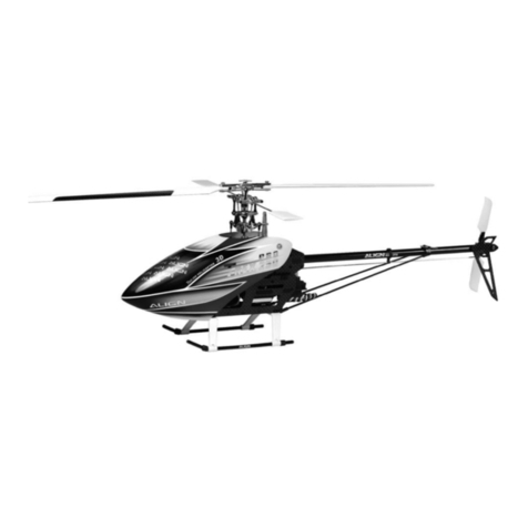
Align Super Combo T-Rex 700E F3C KX018E06T User manual

Align

Align Super Combo T-Rex 700E F3C KX018E06T User manual

Align Trex 600 Nitro KX0160NPTL User manual

Align

Align Trex 600 Nitro KX0160NPTL User manual

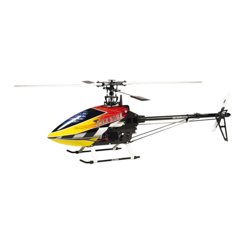
Align Combo T-REX 550E User manual

Align

Align Combo T-REX 550E User manual

Align T-rex 450SE User manual

Align

Align T-rex 450SE User manual

Align T-REX 600 CF User manual

Align

Align T-REX 600 CF User manual

Align T-Rex 450 SE User manual

Align

Align T-Rex 450 SE User manual

Align T-REX 500EFL PRO 3GX User manual

Align

Align T-REX 500EFL PRO 3GX User manual

Align T-REX 600 CF User manual

Align

Align T-REX 600 CF User manual

Align RH55E09XT User manual

Align

Align RH55E09XT User manual

Align Super Combo TREX 500PRO DFC RH50E01XT Troubleshooting guide

Align

Align Super Combo TREX 500PRO DFC RH50E01XT Troubleshooting guide

Align Trex 250 SE KX019005T User manual

Align

Align Trex 250 SE KX019005T User manual

Align T-REX 450X User manual

Align

Align T-REX 450X User manual

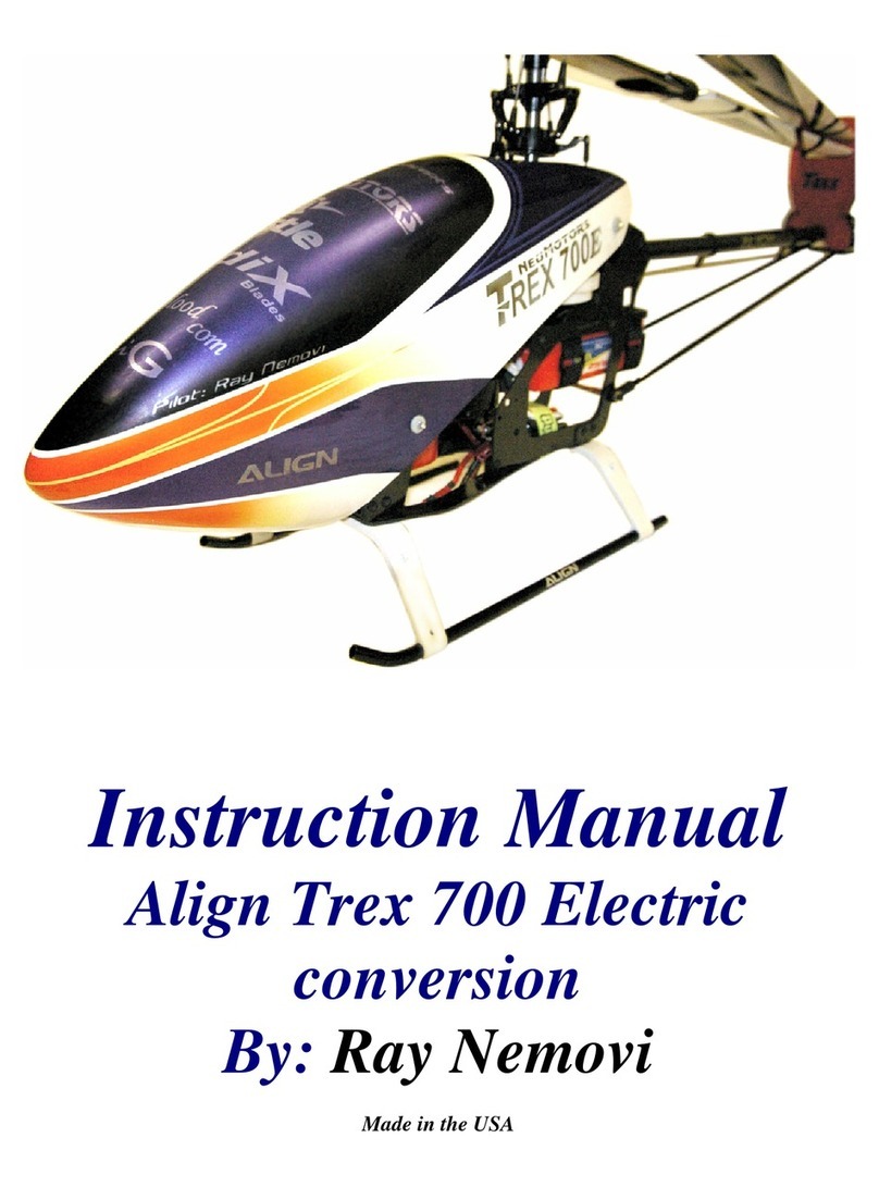
Align Trex 700 Electric conversion User manual

Align

Align Trex 700 Electric conversion User manual

Align Trex 150 SFC RH15E01XT User manual

Align

Align Trex 150 SFC RH15E01XT User manual

Align Trex 500ESP User manual

Align

Align Trex 500ESP User manual

Align Trex 700 Electric conversion User manual

Align

Align Trex 700 Electric conversion User manual

Align T-REX 250PRO DFC KX019011T User manual

Align

Align T-REX 250PRO DFC KX019011T User manual

Align RH50E07XT User manual

Align

Align RH50E07XT User manual

Align T-REX 700E F3C V2 KX018E11T User manual

Align

Align T-REX 700E F3C V2 KX018E11T User manual

Align T-Rex 700 Nitro Pro User manual

Align

Align T-Rex 700 Nitro Pro User manual

Align Trex600 ESP KX016013T User manual

Align

Align Trex600 ESP KX016013T User manual

Popular Toy manuals by other brands

Carl Goldberg Products EXTRA 330 ARF user manual

Carl Goldberg Products

Carl Goldberg Products EXTRA 330 ARF user manual

Mattel Holly Hobbie & friends instructions

Mattel

Mattel Holly Hobbie & friends instructions

Rail King NYC Dreyfuss 4-6-4 operating instructions

Rail King

Rail King NYC Dreyfuss 4-6-4 operating instructions

E-FLITE Tensor 4D Assembly manual

E-FLITE

E-FLITE Tensor 4D Assembly manual

Faller LENGMOOS STATION Assembly instructions

Faller

Faller LENGMOOS STATION Assembly instructions

Super Flying Model Sbach 342 Thunderblot instruction manual

Super Flying Model

Super Flying Model Sbach 342 Thunderblot instruction manual

Fisher-Price Baby Smartronics! 71663 instructions

Fisher-Price

Fisher-Price Baby Smartronics! 71663 instructions

LEGO technic 8110 instructions

LEGO

LEGO technic 8110 instructions

Walachia 36 manual

Walachia

Walachia 36 manual

Eduard Tornado GR.4 quick start guide

Eduard

Eduard Tornado GR.4 quick start guide

MGA Entertainment 272205 operating instructions

MGA Entertainment

MGA Entertainment 272205 operating instructions

MPC 755-12 instructions

MPC

MPC 755-12 instructions

Mattel Barbie GFL82 instructions

Mattel

Mattel Barbie GFL82 instructions

Contixo Kids K81 user manual

Contixo

Contixo Kids K81 user manual

roco 70263 operating manual

roco

roco 70263 operating manual

Mattel Barbie N6285-0520 instructions

Mattel

Mattel Barbie N6285-0520 instructions

Hasbro furReal WALKALOTS E3504 quick start guide

Hasbro

Hasbro furReal WALKALOTS E3504 quick start guide

Blade TR:0 CFX 360 instruction manual

Blade

Blade TR:0 CFX 360 instruction manual

manuals.online logo
manuals.online logoBrands
  • About & Mission
  • Contact us
  • Privacy Policy
  • Terms and Conditions

Copyright 2025 Manuals.Online. All Rights Reserved.