Alke 41 Series User manual

User, Service and Installation Manual
41, 61, 81 Series
Atmospheric ceramic luminous infra-red heaters for use in well ventilated areas
Country of destination:
GB, IE, MT
General international manual
Alke BV
Industrielaan 11a
3925 BD Scherpenzeel
The Netherlands
Tel: +31 33-277 3824
Fax: +31 33-277 3080
www.alke.nl

Version 1.0: March 2018 2 manual number: 0009 0520EN
Warnings
Do:
•Read this manual carefully before installation and use and keep it for future reference. Make sure
that all daily users know the content of this manual.
•Install these heaters only in according with this manual and all applicable local and/or national
regulations for installation and ventilation of gas heaters.
•Improper installation, adjustment, alteration, service or maintenance can cause injury, damage or
death. For assistance or additional information consult your dealer, gas supplier or installer.
•Use these heaters only in well ventilated environment.
•Before installation and use make sure that the required type of gas and gas pressure, as mentioned
on the data plate, is in accordance with the local situation.
•Store gas cylinders always in accordance with national and local regulations.
•Use only gas cylinders with a gas isolation valve or gas lines with a main gas valve at the beginning.
In case more than one heater is connected to a gas system, place also a gas tap directly before the
heaters. Close these taps when the heaters are not in use.
•Installation, maintenance and conversion to other gases shall only be done by competent, qualified
and experienced installers.
•Make sure that during service, maintenance, cleaning and other work on the heaters, gas lines are
closed and the heaters are cooled down.
•These heaters are intended for heating of animals, poultry, barns, workshops, local outside heating
projects and other similar heating purposes in agricultural environment.
•When gas is smelled or a leak is detected, directly close the gas supply and immediately take care
for good ventilation. Do not touch any electrical switch or do not create sparks in another way. Do
not use the system before the leaks are solved and the system is safe again. Consult an installer.
•If a heater is not safe to use anymore, remove it so that nobody accidentally operates the heater.
Store the heater in a safe place, mark that it cannot be used, and contact a service agent or gas
installer to solve the problem.
•This heater has an open flame. Make sure and take action that small children, mentally disabled
persons or elderly people never can touch the appliance or are in the vicinity without supervision.
Do not:
•These heaters are not intended for domestic use or for use in habitable parts of buildings and
houses.
•Never use LPG heaters below ground level or in cellars or basements.
•Never use these heaters in small rooms or insufficient ventilated areas. This can be dangerous and
is forbidden.
•Do not use these heaters for other purposes than room heating. Other use is not foreseen or
evaluated and maybe will be dangerous.
•Do not use another gas or gas pressure than what is written on the data plate.
•Never use these heaters in rooms or areas where combustible liquids or vapours are used or stored
or where there is a danger for dust explosions. These heaters are not ATEX approved.
•Never cover these heaters with cloths or other materials for drying purposes.
•Make sure that never gas lines, gas hoses, electric lines, etc. are mounted directly above the heaters
or are heated by these.
•Take care that gas hoses are not heated above 40 degrees Celsius.
•Never modify heaters. The manufacturer does not take any responsibility for modified heaters.
•Bad installation, wrong adjustment or incorrect maintenance can cause damage, accidents or even
personal injury or death.
•Do not touch, move, handle or service the heater when it is burning or in operation.
General information
Model identification
The main identification of the different models is 41, 61 and 81. These are independent atmospheric
ceramic luminous infra-red heaters. Suffixes are used behind these model names to add additional type
information about the models (e.g. 81-FT).
F: equipped with a single dust filter
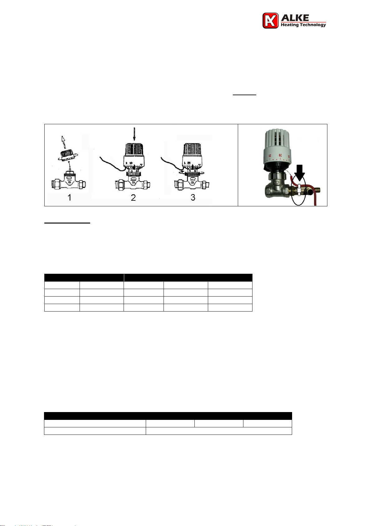
T: equipped with an independent manual thermostat with remote sensor (Ti = integrated sensor)
Packaging
Normally (depending model and order quantity) the heaters are packed per 1, 2, or 4 in a box. The
heaters are pre-assembled. Always check the heaters for transport damage directly after receiving them.

Version 1.0: March 2018 3 manual number: 0009 0520EN
Note that the heaters will be a bit discoloured by temperature due to a 5 minutes quality check after
manufacturing.
The thermostat knob is always delivered separated from the thermostat valve.
1) Remove the protection cover from the thermostat valve.
2) Turn the knob on maximum temperature and push the knob on the valve.
3) Fix the knob by turning the large metal screw ring till it stops (at least 2 turns, hand tight).
For thermostats with a remote sensor only: bend the sensor line carefully (no sharp bends) to the
thermostat valve and secure the sensor line with a ty-rap around the red protection lining and the
thermocouple safety device (see picture). Note that the tubing is hollow, a sharp bend will close the
tubing and makes the sensor worthless. The chance of breaking the line at the entrance of the
thermostat knob is largely limited now.
Installation
Before installation, check that the local distribution conditions, nature of gas and pressure, and
adjustment of the appliance are compatible. Make sure that the gas is clean. Install a gas filter and
condensate trap before the heaters in case the gas is dirty or wet/oily. No guarantee can be given on
heaters operating on gas that is not clean.
Dimensions
Physical dimensions of the appliances (rounded values)
Length (cm)
Width (cm)
Height (cm)
Weight (kg)
41-F
43
32
24
3,7
61-F
47
34
24
4,4
81-F
47
34
24
4,4
81-FT(Ti)
53
34
24
4,8
Place of installation
The heaters are intended for use in well ventilated areas only. Do not install the heaters in situations
that are not well ventilated. See below for more ventilation information. Check also your local regulations
for the ventilation and room size requirements. The number of heaters per building is depending the
type of building, the animals, the insulation, the climate and local wind conditions. Check with your
installer or distributor for a heat transmission calculation to determine the number of heaters needed.
Make sure that the place of installation is free of draft (less than 1 m/s). Too much draft will make the
flames unstable and will result in a lower infra-red heat efficiency. It is advisable to install an alarm
system that reacts on temperature in case a temperature drop will cause damage. Find in the table
below a rough guideline for the installation height to start with. Adjust afterwards to the height based on
local temperature measurements and your personal preference and experience.
Operational Distances
41
61
81
To the ground with animals
100 - 130 cm
120 –150 cm
150 –180 cm
All other applications
Above head level (>2,2 meter)
Safety distance to combustible materials
The heaters produce heat by radiation and by combustion gases. It is important to take the following
distances in account from the heaters to combustible materials. This is to avoid fire or overheating. Do
not use the heaters in situations where the distances to combustibles are smaller. Never store gases or
inflammable liquids or easy combustible materials in close vicinity of the heaters.

Version 1.0: March 2018 4 manual number: 0009 0520EN
Safety Distances
41
61
81
to the ceiling (A)
>50 cm
>60 cm
>60 cm
to the ground. (B)
>60 cm
>90 cm
>90 cm
in front of heater (C)
>50 cm
>50 cm
>50 cm
to the back (D)
>50 cm
>50 cm
>50 cm
to side walls (E)
>50 cm
>50 cm
>50 cm
The minimum distance to non-combustible materials depends on the specific local situation. Keep in
mind that there must be sufficient free space left to vent the combustion gases away. Otherwise, they
will influence the combustion and proper function of the heater. On locations where the combustion
gases can vent away easily, a minimum of 25 cm to the ceiling is advisable. Note: Be aware that some
non-combustible materials can be subject to discolouring when they become too hot.
Warning: be careful with the use of heaters in places with storage of manure. Manure can contain large
amounts of methane and other inflammable gases.
Ventilation
These models of appliances are of the so-called type A1. That means that there is no independent air
supply connection and no flue connection. The flue gasses are vented away by the ventilation of the
space.
A proper ventilation is extreme important for safe and convenient operation. Lack of ventilation can
cause production of carbon monoxide (very poisonous). Sufficient ventilation shall be guaranteed by a
monitored fan or by permanent, non-adjustable, ventilation openings. Consult EN13410:2001 for more
details.
Beside other important requirements this standard EN13410 states in short that a 1,5 times room air
replacement per hour is sufficient in most situations. Also, a maximum of 5W heat input per m3 room
content is considered to be safe. If this is not the case make sure that a minimum of 10m3/h air
replacement per 1 kW heat input is guaranteed by means of fans or ventilation openings.
In case local requirements ask for more stringent ventilation, or when animals ask for more ventilation,
always follow the most stringent requirements. In case there are no requirements or standards for
ventilation in the country of installation, a minimum ventilation of 20m3/h per kW heat input is advisable.
Check regularly if fans are working properly and ventilation openings are not closed.
Game rearing
Ceramic heaters are used a lot for game rearing. Especially for game rearing, due to the small cages
and active birds, pay a lot of attention to cleaning and ventilation. While the cages are small, the effect
of lack of ventilation and not cleaning will be directly cause the death of birds in a short time. While
normally only one heater is used for one cage, we advise to add an independent temperature alarm
system for those situations where a temperature drop due to a (gas)failure will result in bird loss.
Installation
The heaters are intended for suspension only. Mount a chain with a S-hook to the suspension hook of
the heater. The chain and S-hooks shall be galvanised or made of stainless steel. Mount the chain to a
rigid part of the construction of the building. Do not use the gas line, gas hose or electric lines for
suspension purposes. Never use rope or plastic mounting materials. Place the S-hooks at such a place
that the heater reflector makes an angle of approximately 15 degrees to the horizontal and with the gas
safety device at the lower end. Never hang the heater horizontally while in that case the flue gases will
influence a proper combustion. Make sure that in case of draft in the barn, the heaters are turned in
such a way that the radiation surface is not influenced by the draft.
The gas safety device can handle a maximum temperature of 60 degrees Celsius. Be sure that the
heater is not mounted in such a way that this temperature will be reached (e.g. by other heaters in close
vicinity). Take into account the safety distances mentioned on page 3. After installation always check if

Version 1.0: March 2018 5 manual number: 0009 0520EN
the gas type and gas pressure complies with the technical table and data plate information. Remove the
black dust cap from the safety device.
The gas hose shall be hanging free and have a distance of minimal 1 meter from the ground. This to
make sure that animals will not damage the hose. Connect the hose via an individual gas tap to the
central gas supply.
A guideline for placement of the sensor of the temperature regulation is 60 cm above the ground and
minimal 40 cm away from a heater. Use sensors with a black surface in case the regulation is based on
measuring the infra-red temperature.
Gas line supply
In case a main gas line supplies the gas to the heaters, make sure that an authorised company in your
country, in accordance with the local rules and requirements, install the system. To avoid problems, use
galvanised or copper tubing for the gas line. First make a calculation to determine the capacity of the
whole system and the diameters of the piping in each section. Use the common available calculation
methods as written in most gas installation standards. Contact an installer or the distributor in case this
calculation method is not available in your area. For data needed to calculate the dimensions of the gas
line, see the technical table on the last page.
The most common way to install a gas
line is in the centre of the barn (at least
2 meter high) with every 3 to 5 meter a
“T” or “cross” connection for gas supply
to the heaters. Always mount a (easy
reachable) gas tap at the beginning of
the gas hose to the heaters. This gas
tap is needed to close the gas supply to
the burners to extinguish the flames. In addition, it makes it possible to remove the heaters after use or
to service the heaters safely. The gas inlet at the heater side is standard a 8 mm hose nipple (optional
a smooth hose nipple or a G1/8” right handed thread. Other connections are possible after consultation).
Always use approved gas sealant to close the gas connections.
Gas cylinder supply
The gas can also be supplied from LPG gas cylinders. The minimum size is a 11 kg cylinder or larger.
Before buying a cylinder make sure that the connections of the gas regulator and the gas valve of the
cylinder are of the same type. Check with your gas supplier for the correct size of gas regulator. Check
the technical table for the maximum gas consumption and gas pressure.
Store the gas cylinders always on ground level in a well-ventilated place, preferably outside the room
where the heater is. In case the gas cylinder is placed in a cylinder housing, or cover, make sure that
there is enough ventilation as requested by the applicable regulations or standards. Never obstruct these
ventilation holes. Make sure that the gas cylinders are used in upright position only and are secured
again tipping over during use. Gas cylinders laying on their side will give liquid gas. This is very
dangerous and will give a fire ball when it reaches the heaters.
In case the gas cylinder is placed in the same room as the heater is, keep it at a safe distance from the
heater so it will not be over heated. Advisable is at least 2 meters. Make sure that the gas cylinder valve
can easily be reached to close the gas supply in an emergency. Pay special attention how to change
the gas cylinders in a safe way.
For the 41, 61 and 81 it is sufficient to have one gas cylinder (11 kg or larger) per heater. For a 45-kg
gas cylinder a maximum of 3 heaters is recommended. Having more heaters on the gas cylinders as
recommended above can give gas capacity problems, especially when it becomes colder.

Version 1.0: March 2018 6 manual number: 0009 0520EN
Gas hose
In most installations, the heaters are not connected directly to the gas system but a gas hose is used.
Keep the hoses always as short as possible, especially for natural gas and low-pressure LPG. For high
pressure LPG, the maximum length (concerning capacity issues) is 5 meter.
The gas hoses must be inspected frequently and must be changed within the prescribed intervals. Check
the hose at least every 6 weeks. Avoid twisting or stress of the gas hose. Twisting or stress will shorten
the live time of the gas hose. During inspection, check the hose for damage, splitting, ageing and
cracking. Pay special attention to the connections. If a defect is seen directly change the gas hose by a
new one of the same type. Keep the hoses clean from dirt, moisture and dust.
Some countries have regulations that gas hoses must be replaced every 2 or 3 years. Please check
with your gas supplier. Always use official approved gas hoses, suitable for the pressure concerning.
Replace a gas hose always by a type of the same length, internal diameter and equivalent quality. For
safety reasons: never use air hoses or water hoses, these are very dangerous for gas transportation
and will leak soon!
The gas hose shall always be connected to the heater with the help of hose clips. Not using hose clips
at both ends of the gas hose is very dangerous. Make sure that the gas hose never is heated above 40
degrees Celsius.
Changing gas cylinders
In case gas cylinders are used, changing or connecting gas cylinders must be done preferably outside,
or in a well-ventilated area, in a flame-free environment and away from other people.
•Check if there are no other operating heaters, other gas heaters, burning candles or people smoking
cigarettes in the area.
•Be sure that the valve on the gas cylinder is closed and the burner of the heater is extinguished.
•Unscrew the nut by which the gas regulator is connected to the gas cylinder valve. (Note that most
connections are with left-handed threads. They open in clockwise direction).
•Before connecting the (new) gas cylinder, first check if the rubber seals on the cylinder valve or on
the regulator connecting nut are fitted properly and able to fulfil its function and are not damaged or
worn. If the last case is true, do not use it and replace the seals first.
•After connecting the regulator firmly, open the cylinder valve and check with soapy water if the
connection is leak tight. If bubbles appear, the connection leaks. Do not use the heater unless the
system is sound.
Biogas
While biogas can be corrosive under certain conditions it is important that the biogas is clean before
entrance to the appliances. The gas shall be dry and free from dust, oily and greasy particles to avoid
internal blockage of the appliances. Also, halogens, chlorides, H2S and NH3 shall be removed to avoid
corrosion. The tolerance for proper combustion on biogas with a composition of CH4=60% is +/- 4%
CH4.
Soundness check
Before using a new built gas system, first make sure
that the installer made a careful and extensive check
for gas leakage. After executing a pressure drop test
to determine that there are not large leaks, check
every connection with soapy water or gas detection
liquid with all gas valves open and with maximum gas
pressure. Pay special attention to the hose
connections. Maintain maximum air ventilation during the test. Repeat this check at least every year.
This soundness check shall be done by a competent installer only.
Gas leakage
When a gas leak is detected, immediately close the gas supply and disconnect electricity. Keep flames
away. Do not use the heater anymore. Contact an authorised gas technician, gas installer or gas service
agent to determine if the gas leakage can be repaired. Never try to do gas repairs by yourself. Do not
use the heater anymore until the problem is solved.

Version 1.0: March 2018 7 manual number: 0009 0520EN
Operation
New heaters
New heaters need a cleaning period before they are ready for operation. Turn the ventilation to maximum
position or place the heaters outside in the open air. Fire the heaters for at least two hours on full capacity
to burn-off oily and greasy remnants of the production. Make sure that after two hours all smoke and
smell is disappeared. The smoke and smell can be unhealthy, so keep animals and human beings away
till the heaters and the environment air is clean.
Ignition of the heater
Warning: after a heater is extinguished (intentionally or unintentionally) wait always for 3 minutes before
(re)ignition. This is a worldwide safety rule and intended to ventilate unburned gases away and to leave
enough time for the thermocouple device to close.
Ignition shall always be done in high fire position only. After the heater is pre-heated for roughly a minute,
heaters that are allowed to operate in low fire position can be adjusted now to low fire or positions in
between. In poor quality gas conditions, cold ignition can be difficult. Partly covering the air inlet by hand
for a few seconds will help to stabilize the flame.
41, 61, 81 (F and FT versions):
1) Open all gas taps (and turn the thermostat or gas
pressure regulator on maximum).
2) Keep a flame of a BBQ lighter (or long match) in the
ignition hole of the burner gauze near the thermocouple.
3) Press the knob of the gas safety device and wait for
10-25 seconds after ignition before releasing the knob.
4) The burner will stay on now.
5) Repeat al steps again in case the burner directly
extinguishes.
Heat regulation of the heater
41, 61, 81 (F version):
The heat input of this heater can only be changed by adjusting the pressure of the gas supply. Check
the gas supply pressure information on the data plate of the heater for the minimum and maximum
values. If only one pressure per gas is mentioned, adjustment is not possible and only continuous
operation or on-off operation is allowed.
41, 61, 81 (FT version):
Make sure that the gas supply pressure remains constant at the value
indicated on the data plate. Adjust the heat input by setting the
thermostat knob at the desired value. Note that the temperature on the
ground will be several degrees higher than at the sensor. So, use the
setting on the thermostat knob as a rough guideline and always check
the real temperature on the ground
Extinguishing the heater
41, 61, 81 (F and FT versions):
Close the gas tap or the central gas supply. The burner will extinguish now. The thermocouple safety
valve will close within 60 seconds.
Visual examination of the flame
Check after every ignition (and also during regular barn inspection) if a heater still burns correctly. The
flame shall remain always under the burner gauze on the ceramic stone. The ceramic stone shall be
equal red/orange in high firing position after a pre-heating period of at least 5 minutes.
A burner does not operate well in case there is a (green)-blue cloud inside the reflector and under the
burner gauze. Or a (green)blue flame tongue is coming out the exhaust holes in the reflector. This is
only visible in dark conditions. Soot deposit on the reflector and yellow flames are also a sign of bad
functioning and are not allowed. Cleaning will solve these problems in most cases.
In case the burner makes a loud roaring noise and the burner ceramic does not become equal
red/orange but dark, the ceramic is damaged and the flame is burning inside the burner box (back firing).
Directly extinguish the burner and replace the damaged ceramic by a new one.
Approx. Temperature (T)
Δ = 15 °C
* = 20 °C
1 = 22 °C
2 = 28 °C
3 = 33 °C
4 = 36 °C
5 = 38 °C

Version 1.0: March 2018 8 manual number: 0009 0520EN
Service and maintenance
General
The frequency of maintenance is strongly depending on the quality of the combustion air and the
intensity of use. When used in poultry houses, maintenance is advised every 6 weeks or by changing
the animals. By use in clean environment conditions, the maintenance period can be extended but not
longer than 6 months. In case heaters are not used for a long period, always do maintenance first before
using them again. Wear safety goggles during cleaning with compressed air.
Parts that are broken, or are not functioning well, must be replaced directly by identical ones of same
brand and type. Consult the dealer or manufacturer in case of doubt.
WARNING: always switch off the heater and isolate the gas before carrying out any service or
maintenance operation.
Order of maintenance
•First clean the heater and filter as described below by daily maintenance. Especially remove dust
directly behind the venturi.
•Clean the reflector (5) and other parts (excluding the burner ceramics (3) and burner gauze(4)) with
water and mild detergent and a cloth or soft brush.
•Carefully inspect the burner gauze (4) and burner ceramics (3) on damage, cracks and holes.
Replace when needed.
•To clean the burner (1), burner gauze (4) and ceramic stone (3) use an air hose (pressure max 2
bar/30 psi) and blow inside the venturi (12) and on the ceramic stone (3). Do this for 60 seconds
and repeat 2-3 times. Never use water to clean your heater or any steel brush.
•Check the injector (16) for obstructions. Remove obstructions by brushing them away and by using
a pin or drill to clean the injector hole. Make sure that the injector hole does not become wider by
using a pin or drill that is larger than the size stamped on the side of the injector.
•Clean the inside of the gas safety device (23) and injector (16) with compressed air. Make sure that
the pressure of the compressed air is not larger than the 1,5x the pressure stamped on the safety
device (65 or 1400 mbar). Otherwise the rubber seals inside the safety device will become damaged.
•Check the condition of the thermocouple sensor (28). Replace in case the tip is burnt-in already, or
the copper tube is kinked, to avoid unnecessary shut down later on.
•Check all gas carrying parts and connections for gas tightness with leak detection liquid or soapy
water according the procedure in the standards applicable in the local installation situation. Never
use a flame for soundness checks!
•In case a gas hose is used, check this carefully for cracks, wear and other signs of damage or
alteration. Replace it also when the maximum lifetime printed on the hose, or the maximum allowed
by local requirements, has passed.
•Commission the heater after maintenance and check it carefully during first ignition, firing and
extinguishing.
In case the heaters need to be stored for a long time, make sure that no dust, spiders, etc. can enter
the heater. Use the carton packaging box to store the heater, or a plastic bag if the box is not available
anymore, and close this carefully.
Daily maintenance
In dusty or dirty environments check and clean a heater every day. In case a heater is not cleaned
internally, especially the venturi, the heat efficiency will drop and the lifetime of the burner gauze will
become shorter or they will be destroyed. Also, there is a possibility that carbon monoxide (poisonous)
will be produced and soot deposit will occur. To keep the heater internally and externally free of dust is
important. Inspect and clean also every day the combustion air openings into the building and the proper
functioning of exhaust fans.
Dust filter
Dust filters must be check every day and cleaned in case needed. Remove a filter before cleaning. Dry
dust can be removed by tapping the filter softly against a solid surface like the sole of a shoe. The dust
will fall off easy now. In case the filter is still not clean, brush the surface gently with a brush or clean it
with compressed air from inside to the outside. In case the dust is greasy, clean the filter in warm water
with a bit detergent. Make sure that filters are dry before placing them back. Even with the use of a filter
still check the heater regularly inside while very fine dust still will pass the filter and pollute the heater
internally.
Advice: Lots of farmers use a second set of dust filters. They replace the dusty ones directly with the
clean ones and clean the filters outside the barn to avoid unneeded disturbance of the animals.

Version 1.0: March 2018 9 manual number: 0009 0520EN
Internal cleaning
The internal part of a heater can be cleaned with compressed air and with a tube brush. If needed do
this every day. First clean the outside of the burner. Then the inside of the venturi and burner tube via
the dust filter connection. Repeat this 3 times to be sure the dust is removed. Do not hit the ceramics
while it becomes a bit brittle due to the temperature.
Water
Never clean the heater with water, steam or
chemicals. Also, do not use high pressure jets to
clean the heater. The lifetime of the ceramic stone
will go down when it becomes wet and again hot
afterwards or will be destroyed by the water
pressure. In case a heater becomes wet
unintentionally, first make sure that it is dried
completely before using it again.
High fire
The lifetime of infrared heaters in a dusty environment will be extended in case these heaters are
operated on high fire every 12 to 24 hours for minimal 15 minutes. This burns off dust in the burner that
accumulates during low-fire operation. This is only needed in case heaters operate on lower setting for
a longer period. When a barn computer is used for heating and ventilation, it will be easy to modify the
program to add a 15 minutes high fire operation every day. In case a mechanical thermostat is used a
solution can be to put the sensor for 15 minutes in a bucket with cold water during daily inspection of
the barn.
Consumable parts
Thermocouples (28), burner gauzes (4) and the magnet unit (#53 mini (26)) inside the gas safety device
are the most important parts that maybe requires replacement during normal operational life. See the
Parts List for more information.
Replacement thermocouple and magnet unit
- Remove the thermocouple (28) by unscrewing the nut M8 at the gas safety device (23). Open bracket
(8) and remove the thermocouple.
- Unscrew the nut (27) at the gas safety device (23).
- Remove the broken magnet unit (26) and replace by a new one.
- Replace the nut (27) and close carefully (firmly but not excessive) to avoid gas leakage.
- Screw thermocouple nut M8 in nut (27). Hand-tight first and then an additional 1/6 turn. Position of the
thermocouple is that bracket (8) just covers the first turns of the M8 thread on the thermocouple tip.
- Carefully check for gas leakage before taking back into operation.
Conversion instructions
Conversion shall be done by a qualified installer only. To convert a heater from one gas or gas pressure
to another gas or gas pressure, take the following actions.
- Consult the technical table and contact the manufacturer or dealer for the parts needed. (new injector
(16), new venturi (12), new thermostat body (20) and a new data plate).
- Replace the parts by new ones. Use a proper gas sealant to avoid gas leakage and seal the new parts.
- Consult the technical table for the proper ring distance. (Rings are counted from the gas safety device).
- Check the gas supply for the proper gas pressure and gas type and do a leakage test first.
- Take the heater into operation and do a visual examination of the flame as explained above.
End-of life disposal
The infrared heaters are made up of valuable recyclable materials. Therefore, deliver your heater at the
end of its life in a recycling company.

Version 1.0: March 2018 10 manual number: 0009 0520EN
Fault finding table
Trouble
Action
Burner does not light.
•Check if gas valve of the gas cylinder or gas line is open
•Check if gas cylinder is empty
•First ignition will take up to 60 or more seconds before gas is available
•Check if the injector is blocked
•Check if the gas pressure/gas quality is identical to the pressure
indicated on the data plate
Burner extinguishes
after lighting
•Keep button safety device pressed for a longer period (up till 25
seconds)
•Check if the thermocouple is connected properly to the gas safety device
•Check if the thermocouple tip is heated by the flame
•Thermocouple or magnetic coil of the safety device is broken.
•Gas pressure lower than minimum requested
•Heater not suspended at 15 degrees angle
Flames leave the
- confines of the burner,
- or are sooting,
- or a blue cloud is
under the reflector
•Gas pressure is too high. Check the gas pressure with the data plate
•Check if the gas pressure regulator is broken.
•Wrong gas is used. Check data plate for the correct gas supply
•Venturi/air inlet is blocked/dirty
•Check the size of the venturi and injector with the table
•Not enough fresh air available due to mounting situation
•Air filter is dirty
•Heater not suspended at 15 degrees angle
•Check the correct position of the circlip on the nozzle holder
The burner is only
partly glowing
•Wrong gas or pressure is used. Check data plate with the gas supply
•Check if the injector or venturi are blocked or dirty
•Check the injector and venturi size with the table
•Check if pipe sizes or gas hoses have sufficient capacity
•Check the setting of the thermostat
The burner makes a lot
of noise after ignition or
after several minutes
•Wrong gas, wrong gas pressure, wrong venturi or wrong injector is used.
Burner is overheated. Check data plate or technical table
•Check if the ceramic stone is broken or damaged so the flame burns
inside the burner house
The burner does not
work at minimum
position
•Gas pressure is not correct. Check the gas pressure with the data plate
•Wrong gas is used. Check data plate for the correct gas supply
•Check the size of the venturi and injector with the table
•Injector is partly blocked
•Check if thermocouple tip senses the heat
•Sensor or wire thermostat is broken
•Thermostat valve adjusting mechanism is blocked
•By-pass hole thermostat is blocked
Heater will not attain
the desired
temperature
•There is insufficient heat in the building for heat loss (i.e., not enough
heaters).
•The thermostat sensing bulb is incorrectly placed
•The thermostat is out of calibration or broken
•Gas pressure too low
Declaration of conformity
We, Alke B.V., located in Scherpenzeel, The Netherlands, hereby declare that the 41, 61 and 81 series,
marked on their data plates with CE and with CE approval/production supervision by Kiwa (number
0063) are in compliance with the following EU legislation:
- Directive on appliances burning gaseous fuels (GAD) 2009/142/EC (ex 90/396/EEC)
- Regulation on appliances burning gaseous fuels (GAR) 2016/426/EU
Scherpenzeel, 01-03-2018
Adri van Alphen
President

Version 1.0: March 2018 11 manual number: 0009 0520EN
Parts list
Note that the picture shows a model 61 / 81. The picture also can be used to determine the parts of the 101 and 41, although
the parts deviate a little bit in shape.
Part #
Description
No.
Part #
Description
1a
01640010
Burner house 81-15mm venturi
13
01799000
Air inlet connector AK05-25mm
1b
01640011
Burner house 81-11mm venturi
14
07135000
Metal screw
1c
01640013
Burner house 81-18mm venturi
15
02530000
Dust filter
1d
01612000
Burner house 41
16a
011500xx
Injector/nozzle M8x0,75 top 0,50mm *)
2
02475000
Gas distribution plate 81
16b
011520xx
Injector/nozzle M8x0,75 top 1,00mm *)
3
02628100
Ceramic stone 41 LD <100 mbar
16c
011530xx
Injector/nozzle M8x0,75 top 2,00mm *)
3a
02622000
Ceramic stone 41 HD >100mbar
17
01301000
Nozzle holder
3b
02603000
Ceramic stone 61 LD <100 mbar
18
07001000
Circlip E type
3c
02604000
Ceramic stone 81 LD <100 mbar
19
01405000
Reducing ring
3d
02624000
Ceramic stone 81 HD >100 mbar
20
00925010
Thermostat valve
3e
02650000
Ceramic glue
21a
00924130
Thermostat sensor with external sensor
4a
02401000
Burner gauze 41
21b
00923070
Thermostat sensor with internal sensor
4b
02403000
Burner gauze 81
22
01429000
Reducing nipple
5a
02301000
Reflector 41
23a
00106000
Gas Safety Device T10+hose pillar
5b
02304000
Reflector 81
23b
00101010
Gas Safety Device T10+1/8” male
6
07145000
Metal screw + washer
23c
00101030
Gas Safety Device T10+PTP+1/8”male
7
07401000
Nut
24
01327000
Hose pillar
8
03905000
Thermocouple bracket 8mm
25
01328000
Hose nipple
9
07013010
Parker screw
26
00161000
Magnet Unit #53
10
03901000
Suspension hook 41-61-81-101
27
00158000
Nut Gas Safety Device M8x1
11
07010000
Star lock push-on washer
28
00201010
Thermocouple
12
01308999
Venturi 15x30 *)
*) contact dealer/manufacturer for more detail and exact part #
Information for K-gas only (G25.3)
I2EK. Gas G25.3: This appliance is adjusted for the appliance category K (I2K) and is suitable for use of G and G+ distribution
gases according the specifications as written down in the NTA 8837:2012 Annex D with a Wobbe-index of 43,46 –45,3 MJ/m3
(dry, gross, 0°C) or 41,23 –42,98 MJ/m3 (dry, gross, 15 °C).
This appliance also can be adjusted or converted to the appliance category E (I2E) gas G20 and in that case, it is suitable to use
high calorific distribution gases with a Wobbe-index of 49,4 –51,4 MJ/m3 (dry, gross, 15 °C). Precondition for the high calorific
distribution gas is that the composition contains no more than 7% propane, 12% ethane, 1.5% carbon dioxide, 0.5% hydrogen
and 1.8% water vapor, with the total PE number (propane equivalent) not higher than 7 %.
The above limit values for the Wobbe index are the values guaranteed by the EN419 standard tests with the extreme limit gases
applicable to the mentioned appliance categories.

Version 1.0: March 2018 12 manual number: 0009 0520EN
Technical table
Category
Gas
Maximum
Supply
pressure
Minimum
Supply
pressure **
Max.
Heat
Input
Min.
Heat
Input
Gas consumption
Main
Injector (1x)
By-pass
injector
T **(1x)
Venturi
Ring
Injector
Holder
NOx class
Remarks
(-)
(-)
(mbar)
(mbar)
(kW Hs)
(kW Hs)
(g/h or m3/h)
(mm)
(mm)
(mm)
(-)
(-)
(-)
41 series
I2L
G25
25
x
2,0
x
0,22 m3/h
1,05
x
15
4
x
x
I2EK (K)
G25.3
25
x
2,05
x
0,22 m3/h
1,05
x
15
4
x
x
I2H, I2E, I2E+
G20
20
x
1,8
x
0,17 m3/h
0,95
x
15
4
x
x
I2ELL (LL)
G25
50
25
1,9
1,35
0,21 m3/h
0,85
x
9
4
x
x
I2ELL (E)
G20
50
25
1,9
1,35
0,18 m3/h
0,77
x
11
4
x
x
I3P
G31
28
x
1,5
x
107 g/h
0,64
x
15
4
x
x
I3P
G31
50
x
1,65
x
118 g/h
0,59
x
11
5
x
x
I3P
G31
150
50
1,60
0,90
115 g/h
0,46
x
9
5
5
0063CS3361
I3P
G31
200
50
1,85
0,90
132 g/h
0,44
x
9
4
x
x
I3P
G31
1400
500
1,85
1,10
132 g/h
0,27
0,22
6,5
4
x
x
61 series
I2L
G25
25
x
2,6
x
0,29 m3/h
1,20
x
15
2
x
x
I2EK (K)
G25.3
25
x
2,65
x
0,29 m3/h
1,20
x
15
2
x
x
I2ELL (LL)
G25
50
25
2,30
1,60
0,26 m3/h
0,94
x
11
5
5
0063CS3361
I2ELL (E)
G20
50
25
2,30
1,60
0,22 m3/h
0,85
x
11
5
5
0063CS3361
I3P
G31
50
x
2,60
x
185 g/h
0,74
x
15
6
x
x
I3P
G31
150
50
2,70
1,55
193 g/h
0,57
x
11
2
x
x
I3P
G31
1400
500
2,9
1,73
207 g/h
0,34
x
9
2
x
x
81 series
I2EK (K)
G25.3
25
x
3,30
x
0,35 m3/h
1,35
x
15
6
5
0063CS3361
I2H, I2E, I2E+
G20
20
x
3,30
x
0,32 m3/h
1,30
x
18
7
5
0063CS3361
I2ELL (LL)
G25
50
25
3,30
2,30
0,30 m3/h
1,11
x
12
5
5
0063CS3361
I2ELL (E)
G20
50
25
3,20
2,20
0,30 m3/h
1,01
x
12
5
5
0063CS3361
I3P
G31
30
x
2,75
x
195 g/h
0,85
x
18
6
x
x
I3P
G31
50
x
3,0
x
215 g/h
0,80
x
17
4
x
x
I3P
G31
150
50
3,0
1,70
215 g/h
0,61
0,51
11
7
5
0063CS3361
I3P
G31
200
50
3,2
1,60
228 g/h
0,58
0,46
11
4
x
x
I3P
G31
1400
350
3,60
1,80
260 g/h
0,38
0,28
9
2
5
0063CS3361
** In case the heater is equipped with a thermostat (T) with bypass injector the heater shall be operated on maximum supply pressure only. See also the pressure information on the data plate
Conversion calculation from gross heat input kW(Hs) to nett heat input kW(Hi):
Propane: divide gross heat input kW(Hs) by factor 1,09 (example: 1,20 kW(Hs) / 1,09 = 1,10 kW(Hi)
Natural gas: divide gross heat input kW(Hs) by factor 1,11 (example: 1,20 kW(Hs) / 1,11 = 1,08 kW(Hi)
G31 = propane; G20 = natural gas (100% methane); G25 = natural gas (86% methane); G25.3 = natural gas (88% methane); Biogas = 60% methane + 40% carbon dioxide
Other manuals for 41 Series
1
This manual suits for next models
9
Table of contents
Other Alke Heater manuals
Popular Heater manuals by other brands

Glowworm
Glowworm EASICOM 3 Installation and maintenance instructions

Astral Pool
Astral Pool 41429 Installation and maintenance manual

MO-EL
MO-EL LUCCIOLA Use and maintenance

Life Smart
Life Smart LS1006HH13 Owners installation and operating manual

Pro Breeze
Pro Breeze PB-H05 instruction manual

Solaire
Solaire HUBER user guide

Comfort Zone
Comfort Zone CZ277 Series manual

CO/Tech
CO/Tech PN01-800 manual

RealFlame
RealFlame VEKTOR 1100 Installation & operating manual

Heatwagon
Heatwagon HVF110 Installation and maintenance manual

VOGEL&NOOT
VOGEL&NOOT FATALA Assembly and operating manual

BLACK DECKER
BLACK DECKER HX310 Original instructions