Alke AL-8 Series User manual

Version 1: December 2020 1 manual: 0009 0251EN-Alke
User, Service and Installation Manual
AL-8, AL-10, AL-12 Series
Atmospheric ceramic gas infrared heaters for outdoor use
Country of destination:
GB, IE, MT
General international manual
AL-12-SEi-AS
Alke BV
Industrielaan 11a
3925 BD Scherpenzeel
The Netherlands
Tel: +31 33-277 3824
Fax: +31 33-277 3080
www.alke.nl

Version 1: December 2020 2 manual: 0009 0251EN-Alke
Fig. 1a
Fig. 1b
Fig. 1c
Fig. 1d
Fig. 2a
Fig. 2b
Fig. 3
Fig. 4a
Fig. 4b
Fig. 4c
Fig. 5

Version 1: December 2020 3 manual: 0009 0251EN-Alke
1. Warnings
Do:
•Read this manual carefully before installation and use and keep it for future reference. Make sure that all
daily users know the content of this manual.
•A competent and qualified person, like a gas installer or other professional, shall do the mounting,
installation, maintenance and servicing (and conversion to other gases if applicable).
•Install these heaters only in accordance with all applicable local and/or national regulations for installation
and ventilation of gas heaters.
•Improper installation, wrong adjustment, alteration, incorrect service or maintenance can cause accidents,
injury, damage or death. For assistance or additional information consult the dealer, gas supplier or gas
installer.
•Use these heaters only outdoors or in amply ventilated areas, a minimum of 25% of the wall surfaces of
these amply ventilated areas must be open. (see fig. 1a, 1b, 1c)
•Before installation and use make sure that the required type of electricity, type of gas and gas pressure (as
mentioned on the data plate) are in accordance with the local situation.
•Store gas cylinders always in accordance with national and local regulations.
•Use only gas cylinders with a gas isolation valve, or gas lines with a main gas valve at the beginning. In
case more than one heater is connected to a gas system, place also a gas tap directly before each heater.
Close these taps when the heaters are not in use.
•Make sure that during service, maintenance, cleaning and other work on the heaters, gas lines are closed
and electricity disconnected and the heaters are cooled down
•When gas is smelled or a leak is detected, directly close the gas supply and immediately take care of good
ventilation. Do not touch any electrical switch or do not create sparks in another way. Do not use the system
before the leaks are repaired and the system is safe again. Consult an installer.
•If a heater is not safe to use anymore, close the gas supply and electricity to the heater so that nobody
accidentally can operate the heater. Contact a service agent or gas installer to solve the problem.
•These heaters have an open flame. Make sure and take action that small children, mentally disabled
persons or elderly people never can touch the heaters or are in the vicinity without supervision.
•In case the heater is extinguished by an unknown reason, wait for at least 3 minutes before igniting the
heater again.
•Many pictures in this instruction show a type AL-10 heater. But these pictures are also valid for the other
types.
Do not:
•Do not use these heaters for domestic applications or for use in habitable parts of buildings and houses.
•Do not use these heaters below ground level or in cellars or basements.
•Do not use these heaters in small rooms, enclosed areas or insufficient ventilated areas. This can be
dangerous and is forbidden. (see fig 1a)
•Do not use these heaters for other purposes than terrace heating or similar applications. Other use is not
foreseen or evaluated and maybe dangerous.
•Do not use another electricity voltage or type, type of gas or gas pressure than what is written on the data
plate.
•Do not use these heaters in locations where combustible liquids or vapours are used or stored or where
there is a danger for dust explosions. These heaters are not ATEX approved.
•Do not cover these heaters with cloths or other materials for drying purposes.
•Do not install gas lines, gas hoses, electric lines, etc. directly before, above or behind the heaters so they
become heated by the heater or flue gases.
•Do not heat gas hoses above 40 degrees Celsius.
•Do not modify heaters. The manufacturer does not take any responsibility for modified heaters.
•Do not touch, move, handle or service a heater when it is in operation.
NOTE: Sometimes in the text numbers between brackets are used. These numbers correspond with the
numbers of the exploded view and parts list in the back of the manual.

Version 1: December 2020 4 manual: 0009 0251EN-Alke
2. General information
Model identification.
The main identification of the different models is AL-8, AL-10 or AL-12. These are independent atmospheric
ceramic gas infrared heaters. Suffixes are used behind these model names to add additional information about
the models (e.g. AL-8-SEi-AS).
S: equipped with an individual solenoid valve for high-low operation
Ei: equipped with an electronic ignition device (EID2G)
AS: equipped with an asymmetric reflector
ER: equipped with an economy reflector
See the technical table in chapter 12 for the different gas situations.
Working principle of the heaters.
These heaters provide heat through infrared radiation. Infrared heating is the only heating principle for an
efficient heating comfort in outdoor situations. It is comparable with sitting in the sun on an early spring day: the
air temperature is still low but the radiation of the sun makes it nice and comfortable. These heaters have a
short heating up time: infrared heat is available directly on request.
Safety in general
The heaters comply with the European Gas Safety requirements. An independent test house has approved a
prototype in accordance with the European Standards and the Gas Appliance Regulation. After approval the
factory is inspected every 6 months by a Notified Body to monitor the production of the certified heaters.
Unpacking the heater.
The carton box will contain the following parts:
•1 heater with reflector
•1 manual
Components ordered additional (like mounting brackets or gas hoses) are delivered separately. Please check
the heater on transportation damage, etc. before acceptance. Contact directly the transporting company or the
dealer in case the carton box and heater are damaged.
Before leaving the factory, all the heaters are operated and tested by the manufacturer on gas for 5 minutes.
Note that due to this the burner and reflector of the heater will be a little bit discoloured.
Weather conditions
The heater is made of strong and durable materials. Rain or moisture shall not directly shorten lifetime of the
heater (as long as the burner stones remain dry) but of course it is better to protect the heater from these
influences. The heater will not efficiently work with strong winds. The wind will make ignition difficult or cools
down the safety device, which will cut off the gas supply to the burner. We advice not to use the heater by wind
speeds above 3 m/s (3 Beaufort).
In a corrosive environment (like coastal area’s or some industrial places) is it possible that parts of the heater
show signs of corrosion. In first instance this will not influence safe functioning of the heater. During the yearly
service check the evaluation must be made if this is still the case. No guarantee is granted to parts that are
corroded or damaged due to placement in a corrosive environment.
3. Installation
General
A competent and qualified person, like a gas installer or other professional, shall do the mounting and
installation. In particular this is applicable for the gas technical and electrical part of the installation. Install this
heater always in accordance with the applicable gas technical and electrical regulations, local and national
installation regulations and with the requirements written in this manual. Before the final delivery of the heating
installation the installer shall check the complete system for gas leakage and electrical safety and operate the
heater to check for safe and proper functioning.
These heaters are of the so-called type A1. That means that there is no independent combustion air supply
connection and no flue connection. The flue gasses are vented away by the ventilation of the space.
The heaters are intended for outdoor use only or amply ventilated areas but not for indoor heating. (See fig. 1a,
1b, 1c). When local regulations allow it, there are no safety objections to use the heater in large indoor spaces
for spot heating where space and ventilation conditions are comparable to outdoor use (like exhibition halls,
covered shopping streets, etc). First check with the local authorities in these situations. Never use the heater in
small indoor spaces.

Version 1: December 2020 5 manual: 0009 0251EN-Alke
Heater dimensions
Dimensions of the heaters (rounded values)
Model
Length A
(cm)
Length B
(cm)
Width C
(cm)
Height D
(cm)
Height E
(cm)
Height F
(cm)
Weight
(kg)
AL-8-Ei-AS
66
57
44
29
30
34
7,6
AL-8-SEi-AS
73
57
44
29
30
34
7,8
AL-10-Ei
87
76
42
34
33
40
9,9
AL-10-SEi
87
76
42
34
33
40
10,4
AL-10-Ei-ER
81
63
45*
39
40
NA
9,5
AL-10-SEi-ER
81
63
45*
39
40
NA
10,0
AL-10-Ei-AS
87
75
44
29
27
34
9,5
AL-10-SEi-AS
87
75
44
29
27
34
10,0
AL-12-Ei
106
94
42
34
33
40
11,8
AL-12-SEi
106
94
42
34
33
40
12,3
AL-12-Ei-ER
99
81
45*
39
40
NA
11,4
AL-12-SEi-ER
99
81
45*
39
40
NA
11,9
AL-12-Ei-AS
105
94
44
29
27
34
11,4
AL-12-SEi-AS
105
94
44
29
27
34
11,9
*) While the heater with the ER reflector does not have brackets, this is the largest width seen from aside.
AL-8, -10, -12 Dimension drawing
Safety distance to combustible materials
The heaters provide heat by radiation and by combustion gases. It is important to take into account the distances
as mentioned in the table from the heaters to combustible materials. This is to avoid risk of fire. Do not use the
heater in situations where the distances to combustibles are smaller or take additional protective actions. Pay
special attention to materials that can move by wind easily in front of the burner, like curtains. Keep these
materials always on a distance of 1 meter or more.
Find in the table below the safety distances from the edge of the reflector to the walls/objects concerned. Realize
that these distances are safety distances in relation to fire safety. This means that temperatures still can rise to
50 degrees Celsius above ambient temperature (= the limit given in the standards). Be alert on possible other
problems, like discolouring. In case of doubt, keep more distance.
Distance to combustible materials (installation angle 45 degrees). See fig. 5
Model
AL-8
AL-10
AL-12
Upper edge reflector to:
[A] - combustible ceiling
[A] - combustible sunshade cloths
60 cm
80 cm
90 cm
Lower edge reflector to:
[B] - combustible back-wall
18 cm*
18 cm*
18 cm*
[C] - the ground
240 cm
260 cm
280 cm
Front plane of the reflector to:
[D] - objects within radiation reach
120 cm
130 cm
160 cm
Side edge reflector to:
[E] - combustible side-walls
50 cm
50 cm
50 cm
*) This distance is guaranteed when the suspension bracket (number 24) is used.

Version 1: December 2020 6 manual: 0009 0251EN-Alke
The minimal distance to non-combustible materials depend on the location but must be at least 30 cm to the
ceiling and side walls. Be aware that some non-combustible materials will discolour when they become to hot.
Combustible materials can be covered with non-combustible materials to minimize the mounting distances.
Inform with a professional about which non-combustible materials can be used and the minimum thickness
needed. Always do a practical test with an operating heater to check the final temperatures of the walls and
objects.
Ventilation around the heater
Check if there is sufficient space for the combustion gases to vent away, but also if there is enough fresh air
available at the inlet of the venturi (14) to the burner. If this is not the case, this will have an influence on the
proper combustion and good functioning of the heater. Sooting, long flames and CO emission can occur which
is not allowed. Also condensation of water can happen. Installation in between ceiling beams can be a situation
where fresh air access will be limited (see also fig. 1d).
Note: electric components shall not reach temperatures above 60 degrees Celsius. Make sure that the electric
components (Ei and/or S) after mounting of the heater are sufficient cooled by fresh air and that the combustion
gases never can touch these components. Check this during the first operation of the heater.
Heating plan
The location of infrared heaters on a terrace needs the advice of an experienced specialist. Especially when
more heaters are used with limited installation space in relation to windows, doors and ceiling height. Also the
location in relation the wind direction, open field, beach or urban environment, open air or under a veranda are
important for a good advice. Ask the dealer for more information and a heating plan. Check always the safety
distances to combustible materials as given above.
Mounting
Mount the heater firmly with metal brackets on the wall or other construction. Make sure that the heaters are
mounted with the ceramic burner plaques pointing downwards under an angle of 45 degrees with the horizontal.
(see Fig. 6). The long side of the reflector shall be water level in the horizontal surface. For suspension purposes,
the brackets of the heaters with the symmetric and asymmetric reflector have 4 holes of ø 8,5mm in a
rectangular pattern. Centre to centre 50mm above each other and centre to centre 180mm side by side. Check
always the location and dimensions of the holes on the heaters first before drilling holes, etc. The heaters with
the economy reflector (ER) have 4 mounting holes of ø 8,2mm in the reflector to attach a chain with the help of
carabiners 6x60mm or eyebolts for suspension.
Note: never use a rope or plastic material to mount the heater. Never use the gas line to mount the heater on.
The gas safety device and electric components can handle a maximum temperature of 60 degrees Celsius. Be
sure that the heater is not mounted in such a way that this temperature will be reached (e.g. by other heaters in
close vicinity).
4. Gas supply information
General
Make sure that an authorised company in the country, in accordance with the local rules and requirements,
installs the gas supply system. Check first if the local gas supply situation and electric supply complies with the
information on the data plate of the heater. Make sure that the gas is clean. Install a gas filter and condensate
trap before the heaters in case the gas is dirty or wet/oily. No guarantee can be given on heaters operating on
gas that is not clean.
Always mount a (easy to be reached) gas tap at the end of the gas line. This gas tap is mandatory to make it
possible to isolate or to remove the heater after use. For data needed to calculate the dimensions of the gas
line, see the technical table.
The screw of the pressure measuring nipple on the gas safety device is susceptible to damage. Use a well-
fitting screwdriver #3.
Gas line supply
In case a main gas line supplies the gas to the heaters, make sure that an authorised company in the country
installs the system. To avoid problems, use galvanised or copper tubing for the gas line. First make a calculation
to determine the capacity of the whole system and the diameters of the piping. Use the common available
calculation methods as written in gas pipe installation standards.

Version 1: December 2020 7 manual: 0009 0251EN-Alke
Gas hose (in combination with gas line supply)
According to the standard EN419 the connection of the gas heater to the gas line shall be done by a gas hose
with a length of minimal 0,5m to maximum 2,0m. This gas hose shall be made of stainless steel, shall be
approved according EN14800 or a comparable standard that is appointed by the local authorities.
Gas cylinder supply
Gas can also be supplied from LPG gas cylinders. The minimum recommended size is a 11-kg gas cylinder or
larger. Before buying a gas cylinder make sure that the connections of the gas regulator and the gas valve of
the gas cylinder are of the same type. Check with the gas cylinder supplier for the correct size of gas regulator,
and check whether the capacity is enough for the heater(s) that will be supplied. Check also whether the location
of the gas cylinder during use is a safe location and according to the local requirements. Check the technical
table for the maximum gas consumption and gas pressure.
Store the gas cylinders always on ground level in a well-ventilated place, preferably outside the room where the
heater is. In case the gas cylinder is placed in a cylinder housing, or cover, make sure that there is enough
ventilation as requested by the applicable regulations or standards. Never obstruct these ventilation holes. Make
sure that the gas cylinders are used in upright position only and are secured against tipping over during use.
Gas cylinders laying on their side will give liquid gas. This is very dangerous and will give a fire ball when it
reaches the heaters. Make sure that the gas cylinder valve always can be reached easily to close the gas supply
in an emergency. Pay special attention how to change the gas cylinders in a safe way.
Gas hose (in combination with gas cylinder supply)
A gas hose must be inspected frequently and must be changed within the prescribed intervals. Check the hose
every time the gas cylinder is changed, but at least once a month. Avoid twisting or stress of the gas hose.
Twisting or stress will shorten the lifetime of the gas hose. During inspection, check the hose for damage,
splitting, aging and cracking. Pay special attention to the connections. Keep the hoses clean from dirt, moisture
and dust.
Some countries have regulations that gas hoses must be replaced every 2 or 3 years. Please check with the
gas supplier. It is advisable to change the hose every 3 years in case there are no local regulations. Always use
official gas hoses. Replace a gas hose always by a type of the same length, internal diameter and equivalent
quality. For your own safety: never use air hoses or water hoses. These hoses are not suitable gas
transportation and will leak quickly!
The gas hose shall always be connected to the heater with the help of hose clips. Not using hose clips at both
ends of the gas hose is very dangerous. Make sure that the gas hose never is heated above 40 degrees Celsius.
Changing gas cylinders
Changing or connecting gas cylinders must be done carefully outside, or in an amply ventilated area, in a flame-
free environment and away from other people.
•Check if there are no other operating terrace heaters, other gas appliances, burning candles or people
smoking cigarettes in the area.
•Be sure that the valve on the gas cylinder is closed, electricity to the heaters is disconnected and the burners
of the heater are extinguished.
•Unscrew the nut by which the gas regulator is connected to the gas cylinder valve. (Note that most
connections are with left-handed threads. They open in clockwise direction).
•Before connecting the (new) gas cylinder, first check whether the rubber seals on the cylinder valve or on
the regulator-connecting nut are fitted properly, are not damaged or worn and able to fulfil its function. If
damaged or worn, do not use it or replace the seals.
•After connecting the regulator firmly, open the cylinder valve and check with soapy water if the connection
is leak tight. If bubbles appear, the connection leaks. Do not use the heater unless the system is sound.
Soundness check
Before using a new built gas system, the installer shall make a careful and extensive check for gas leakage.
After executing a pressure drop test to determine that there are not large leaks, check every connection with
soapy water or gas detection liquid with all gas valves open and with maximum gas pressure. Pay special
attention to the hose connections. Maintain maximum air ventilation during the test. Repeat this check at least
every year. This soundness check shall be done by a competent installer only.

Version 1: December 2020 8 manual: 0009 0251EN-Alke
What to do by gas leakage
When a gas leak is detected, immediately close the gas supply and electricity to the heater. Keep open flames
away. Do not use the heater anymore and inform other people that possibly will operate the heater. Contact an
authorised gas technician, gas installer or gas service agent to determine if the gas leakage can be repaired.
Never try to do gas repairs by yourself. Do not use the heater anymore until the problem is solved.
5. Electrical information
General
All electrical connections/installations shall be made in accordance with the national and/or local regulations
that are in force in the country of destination where the heater will be installed. Before doing maintenance or
installation work always disconnect the electricity to all the lines by removing or disconnecting the fuses from
the electrical system to the heaters.
A proper earth connection MUST be made to the heaters with an electronic ignition device (Ei) and/or with a
solenoid valve (S). Firstly for safety reasons and secondly the electric ignition device (Ei) will not operate
correctly and will give failures or will shut down. The Ei device is not phase sensitive. In case of an electrical
fault directly after installation of the heater concentrate first on earth continuity and resistance to earth. These
are the main reasons for failures while all heaters are operated for proper functioning before leaving the factory.
To maintain the IP65 rating make sure that the rubber seals between the ignition device and electric connector
and between the electric connector and electric wiring are in place. Turn the mounting screws and compression
nuts of the connectors firmly so no water can enter.
Fuses and switches are not supplied with the heater. The electric installation shall have a separate fuse for the
protection of the heaters only. The operation switches prior to the heaters shall be of a double pole type with
minimum contact separation of 3 mm. Make sure that always the live wire (or hot wire) of the electric supply is
used to switch the heaters on and off. The operating or control box, which is not delivered by the manufacturer
but by the installer, can be installed on any desired place and height, provided this is within reach of the user.
Electrical data
Ei
SEi
Electrical supply:
230VAC 50/60Hz, IP65
230VAC 50Hz, IP65
Power:
Max 30VA
Max 50VA
Current rating:
Max 0,2A
0,3A
Waiting time T(w)
7 seconds
7 seconds
Safety time T(s)
30 seconds
30 seconds
Schematic diagram electronic ignition device
Timing diagram electronic ignition device

Version 1: December 2020 9 manual: 0009 0251EN-Alke
Typical lay-out for the connection of the electric lines
1
To control box
2
To additional zones
SW1
Switch on/off
SW2
Switch high/low fire
BR
Brown
BL
Blue
YE
Yellow/Green = Earth
Ei
Electronic Ignition Device
S
Solenoid for high/low
NB: dotted line is only applicable for
the …S…models
6. Operation
New heaters
New heaters need a short cleaning period before they are ready for operation. Fire the heaters for at least 30
minutes on full capacity to burn-off oily and greasy remnants of the production. Make sure that after 30 minutes
all smoke and smell is disappeared.
Ignition of the heater
Warning: after a manual operated heater is extinguished (intentionally or unintentionally) wait always for 3
minutes before (re)ignition. This is a worldwide safety rule and intended to ventilate unburned gases away and
to leave enough time for the thermocouple device to close.
Note: ignition shall always be done in high fire. To do so, the gas pressure shall be adjusted at maximum
(nominal) pressure as indicated on the data plate, solenoid valves shall be in open or high fire position. If desired,
the heat input of the heater can be set to low fire after about 30 seconds after ignition.
Note: If 10 ignition attempts are made in sequence within a short interval (<120 seconds per ignition attempt)
the electronic ignition device will fall into a safety lockout and needs a reset (cool down period) for 20 minutes.
During the reset, leave the power on to feed the internal reset timer.
Electric operated heaters
Ignition of the heater
1) Open all gas taps and turn the gas pressure regulator (if mounted) on maximum pressure according the
dataplate, open the solenoid valve (S)(if mounted) by electricity. (Fig. 2a, 2b). In case the heater has a high/low
fire setting, ignite always in high fire position.
2) Press the switch to operate the ignition device (Fig. 3). The heater will start the ignition program.
3) After a safety time of 7 seconds the ignitor sparks for 30 seconds and ignites the heater.
4) After 30 seconds, the thermocouple safety device will take over the safety function and supervises the
flame. The burner will stay on as long as there is 230V supply on the electric ignition device (Ei).
5) If ignition fails, turn the power to off for at least 1 second to reset the system.
Extinguishing of the heater
Switch-off the electric power supply to the electronic ignition device (Ei) (Fig. 4a). This will close immediately
the gas supply by the gas safety device. Close the gas tap or the central gas supply (Fig. 4b, 4c).
Heat regulation of the heater
All models, except models with …S…
The heat input of these heaters can only be changed by adjusting the pressure of the gas supply. In the gas
line an adjustable pressure regulator shall be mounted or a special device must be installed to regulate the gas
pressure. Check the gas supply pressure information on the data plate of the heater for the minimum and
maximum values. If only one pressure is mentioned on the data plate, adjustment is not possible and only
continuous operation or on-off operation is allowed.
All models with …S…
Make sure that the gas supply pressure remains constant at the value indicated on the data plate. Adjust the
heat input between high and low by opening or closing the solenoid valve (S).

Version 1: December 2020 10 manual: 0009 0251EN-Alke
How to check correct operation of the burner
Directly after ignition the burner flames are blue (difficult to see during daylight). After 15 seconds the ceramic
burner stone starts glowing and becomes red/orange. After 2-5 minutes the heater reaches the maximum heat
output. During normal functioning, the ceramics are glowing red/orange. The burner gauze (20) in front of the
ceramics will be a bit red, but flames (blue or yellow) shall not appear outside the gauze. The burner shall only
make a soft buzzing noise. Other noises or roaring noise indicates that cleaning or maintenance is needed.
Note: during pre-heating (or cooling down) the heater can make a ticking noise. This is created by the expansion
of the material during the temperature change and is not harmful for the heater.
What to do if the heater is not used for a period of time
The heater can stay in place when it will not be used for a period of time. Close all gas valves. When the heater
is mounted in a location protected against wind and rain, no other protection is needed. In case the heater will
become wet by rain or snow (combined with wind) it is better to protect the heater outside the season with a
plastic bag or otherwise. This also protects against dirt.
Take into account the local requirements for long-time storage of the gas bottles out of season. In most places
it is only allowed outside in a protected location or in a well ventilated area. The local fire department,
environmental department of the municipality or gas supplier can inform you about the regulations.
Note: a wet heater can be damaged by frost
Note: do not forget to remove the protection material before using the heater again
7. Cleaning, maintenance and servicing
General
Always shut off the gas valve and disconnect electricity before maintenance or service is done on the heater.
General maintenance and service shall be done at least once a year before the heating season starts or after
a long period the heater is not used. Parts that are broken, or are not functioning well, must be replaced directly
by identical ones of same brand and type. Consult the dealer or manufacturer in case of doubt.
Dust filter (Optional)
Optional dust filters must be checked a few times during the heating season and cleaned in case needed.
Remove a filter before cleaning. Brush the surface gently with a brush or clean it with compressed air from
inside to the outside. In case the dust is greasy, clean the filter in warm water with a bit detergent. Make sure
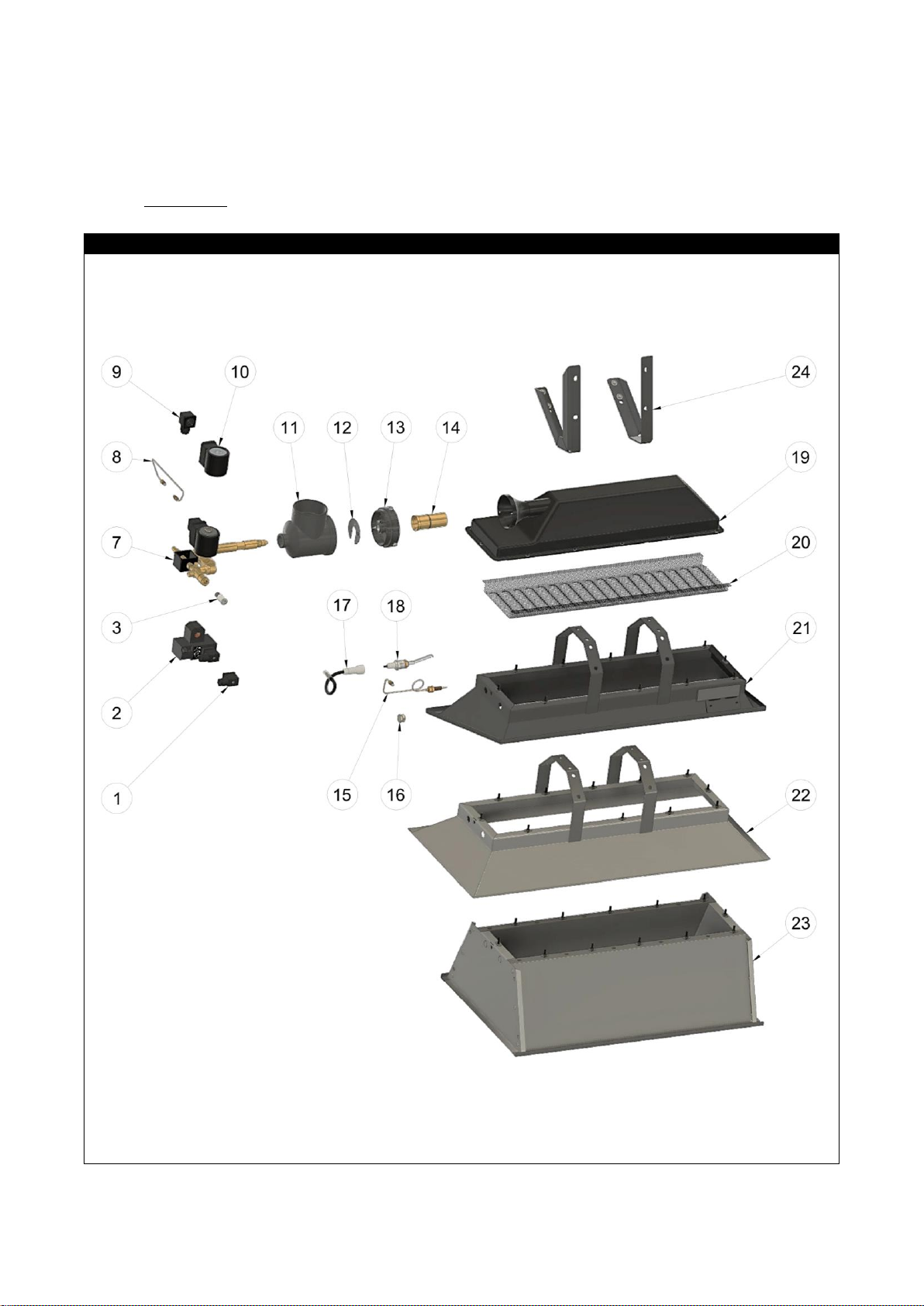
that filters are dry before replacing them. For heaters with a dust filter still check the venturi (14) inside regularly
while very fine dust still will pass the filter and pollute the heater internally.
Order of maintenance
•First clean the heater (and the optional filters) as described above.
•Clean the reflector (21, 22, 23) and other parts with water, mild detergent and a cloth or soft brush.
•Clean the inside of the venturi (14) and burner tube via the connection piece (11) with compressed air and
a tube brush. Repeat this 3 times to be sure that all the dust is removed.
•Carefully inspect the burner ceramics on damage, cracks and holes and if they are still mounted properly.
Replace when needed. To clean the burner ceramics, use low pressure air. Clean first the ceramic stones
with air from the front side through the gauze. Then clean the inside of the burner with air via the venturi
tube. Do not use compressed air above 2 bar because higher pressure will damage the ceramic stones.
Never clean the burner stones with water.
•Check the gas injector for obstructions. Remove obstructions by brushing them away and by using a pin or
drill to clean the injector hole. Make sure that the injector hole does not become wider by using a pin or drill
that is larger than the size stamped on the side of the injector.
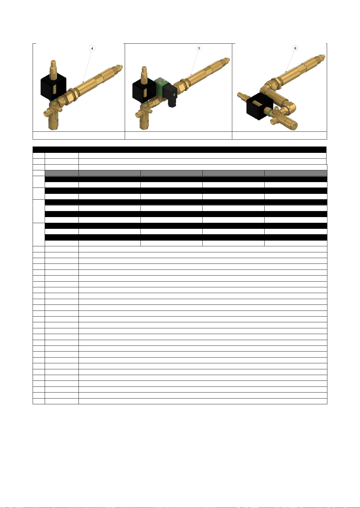
•Clean the inside of the gas safety device (4, 5, 6 or 7) and injector with compressed air. Make sure that the
pressure of the compressed air is not higher than the 0,5 bar. Otherwise the rubber seals inside the safety
device will become damaged.
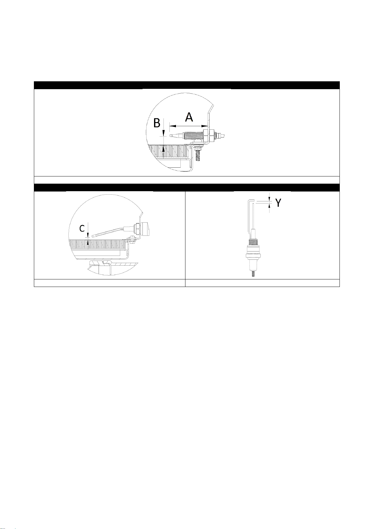
•Check the condition of the thermocouple tip (15). Replace in case the tip is burnt-in already to avoid
unnecessary shut down later on. See additional information for the location of the thermocouple.
•Check the condition of the spark plug (18); no cracks of the ceramic and a spark gap of 3-4 mm. Check if
the metal spark wire and earthing wire still makes a 15 degrees angle directly above the ceramics and are
not bending away to smaller angles. Clean the electrodes with grinding paper in case they are corroded.
•Clean the ignition device and check the connection of the ignition wire for proper contact and waterproofing.
Check if the ignition wire is not damaged and has no cracks.
•Check all gas carrying parts and connections for gas tightness with leak detection liquid or soapy water
according the procedure in the standards applicable at the local installation situation. Never use a flame for
soundness checks!

Version 1: December 2020 11 manual: 0009 0251EN-Alke
•In case a gas hose is used, check this carefully for cracks, wear and other signs of damage or alteration.
Replace it also when the maximum lifetime printed on the hose, or the maximum lifetime allowed by local
requirements, has been passed.
•Commission the heater after maintenance and check it carefully during first ignition, firing and extinguishing.
In case the heaters need to be stored for a long time, make sure that no dust, spiders, etc. can enter the heater.
Use the carton packaging box to store the heater, or a plastic bag if the box is not available anymore, and close
this carefully.
Consumable parts
Thermocouples (15) and the magnet unit (3) inside the gas safety device are the most important parts that
maybe requires replacement during normal operational life. See the parts list for more information.
Replacement of the magnet unit
•Unscrew the thermocouple extension (8) at the gas safety device (4, 5, 6 or 7) by using spanner #8.
•Unscrew the nut for connection of the thermocouple (or thermocouple extension) at the gas safety device
(4, 5, 6 or 7) by using spanner #17.
•Remove the broken magnet unit (3) and replace by a new one.
•Replace the nut for connection of the thermocouple (or thermocouple extension) by using spanner #17 and
close carefully (firmly but not excessive) to avoid gas leakage.
•Replace the thermocouple extension (8) at the gas safety device (4, 5, 6 or 7) by using spanner #8.
•Carefully check the gas safety device for gas leakage before taking back into operation.
Replacement of the thermocouple
•Remove the thermocouple (15) at the connector of the ignition device (2) by unscrewing the nut M8 of the
thermocouple by using a spanner #8.
•Loosen the nuts M8x1 (2x) at the tip of the thermocouple by using a spanner #13 and remove the
thermocouple from the reflector.
•Replace with a new thermocouple until the position as indicated in the drawings below. Tighten nut M8x1
(2x) to secure the thermocouple in place.
•Bend the new thermocouple in the identical shape as the old one the and screw the thermocouple nut M8 in
the connector of the ignition device (2). Hand-tight first and then an additional 1/6 turn.
Replacement of the gas injection set/air restrictor
•Disconnect the heater from the gas line and disconnect the electric connector (1) from the ignition device (2)
(and electric connector (9) from the coil (10) for the S models only).
•Disconnect the thermocouple from the ignition device (2) and disconnect the spark plug wire (17) from the
ignition device (2).
•Loosen the nut M20 on the gasway directly after the air inlet connection (11) by using a spanner #25.
•Loosen the M6 screw on the air inlet connection (11) (directly aside the M20 nut). The air inlet connector can
turn freely now around its axis.
•A spanner #17 can be placed through the filter opening of the air inlet connector on the gasway. Turn anti-
clockwise to loosen the gasline from the spider (13). Turn the gas injection set till it comes separated from
the spider (13).
•The air restrictor (12) can be replaced or removed now from the spider.
•Repeat the procedure above in reversed order to mount all parts back again.
Conversion instructions
Conversion shall be done by a qualified installer only. To convert a heater from one gas or gas pressure to
another gas or gas pressure, take the following actions.
•Consult the technical table on the last page and contact the manufacturer or dealer with the model number
and serial number for the parts needed. (e.g. a new gas injection set (4, 5, 6 or 7), a new air restrictor (12)
or a new venturi (14) and a new data plate).
•Replace the parts by new ones. Use a proper gas sealant to avoid gas leakage and seal the new parts.
•Check the gas supply for the proper gas pressure and gas type and do a leakage test first.
•Take the heater into operation and do a visual examination of the flame as explained above.

Version 1: December 2020 12 manual: 0009 0251EN-Alke
End-of life disposal
The infrared heaters are made up of valuable recyclable materials. Therefore, deliver the heater at the end of
its life in a recycling company.
Position of thermocouple
Position thermocouple AL-8, AL-10, AL-12
A= 33 mm, B= 12 mm
Position of the spark plug
Spark gap
C= 5 mm
Y = 3-4 mm

Version 1: December 2020 13 manual: 0009 0251EN-Alke
8. Fault finding
Trouble
Cause
Burner does not light.
Spark is available
•The gas valve of the gas cylinder (or gas line) is not open
•Gas cylinder is empty
•Air in the (new) gas lines
•Gas injector is blocked
•Gas pressure/gas quality is not corresponding with the data plate info
•The burner is not on high-fire setting during ignition
•The (optional) solenoid valve S is not connected or is damaged
•During sparking manual ignition is possible with a lighter: check the location of
the spark gap related to the ceramic stone is correct
•Gas safety device does not open with a “click” during ignition period, the Ei coil
is broken. Replace.
Burner does not light.
No spark available
•No 230 Volt available at the Ei
•Spark electrode line is not connected to the Ei
•Spark electrode gap incorrect. Shall be between 3-4 mm
•Spark jumps off to other metal parts before the spark electrode. Check wire,
connectors and ignitor ceramics. Check if parts are dry
•Ignition loop is not complete. Check the ignition wire and earthing wire
•Ignitor Ei is broken. Replace
•Ei is in recovery phase. Leave the Ei connected to 230V for 20 minutes to reset
and try again
Burner extinguishes after lighting
•Position of the thermocouple is wrong (see above)
•Thermocouple nuts are not connected properly to the gas safety device and to
the Ei unit, or the nuts are loose
•Thermocouple is not heated by the flame or not mounted properly
•Thermocouple switch in Ei is broken. Check (after switching 230V to the Ei) by
multi meter if resistance of the internal switch is <25 mΩ
•Thermocouple and/or magnetic coil of the safety device are broken.
•Gas pressure lower than minimum requested
•Heater not suspended at 45 degrees angle (facing downwards)
•Not all burner stones are ignited, especially near the thermocouple
Flames:
- leave the confines of the burner
- or are sooting
- or a blue cloud is under the
reflector
•Gas pressure is too high. Check the gas pressure with the data plate
•Gas pressure regulator is broken
•Wrong gas. Check data plate for the correct gas supply
•Venturi/air inlet is blocked/dirty
•Venturi and injector wrong. Check with the technical table
•Not enough fresh air available due to mounting situation
•Air filter is dirty
•Heater not suspended at 45 degrees angle
The burner is only partly glowing
•Wrong gas or gas pressure. Check data plate for the gas supply information
•Injector or venturi are blocked or dirty
•Injector and venturi size are wrong. Check with the technical table
•Pipe sizes or gas hoses have insufficient capacity
•Setting of the thermostat is wrong
The burner makes a lot of noise
after ignition or after several
minutes
•Wrong gas. Check data plate for the gas supply information
•Burner stone is damaged, the flame burns inside the burner house
•A buzzing noise of the Ei is created by magnetic fields and lasts only 30
seconds. Not harmful and temperature dependent. Turn the Ei in another
position.
The burner does not work at
minimum heat input
•Gas pressure is not correct. Check the gas pressure with the data plate
•Wrong gas. Check data plate for the correct gas supply
•Size of the venturi and injector is wrong. Check with the technical table
•By-pass hole solenoid valve (S) is blocked
•Injector (partly) blocked
•Thermocouple has not the proper location to the ceramic burner
Heater will not attain the desired
temperature
•The solenoid valve (S) is not functioning
•Injector partly blocked

Version 1: December 2020 14 manual: 0009 0251EN-Alke
9. Parts list
Consult the dataplate on the heater to determine the model you have. For spare parts, service material, advice
and information please contact the distributor. Always mention the model name and serial number. Service
parts are only available via the distributor or gas installer. For general manufacturers information please see the
internet: www.alke.nl
Overview Parts AL-8, -10, -12

Version 1: December 2020 15 manual: 0009 0251EN-Alke
Number 4
Number 5
Number 6
Nr
Art. number
Description
1
03025000
Rectangular Electric Connector 3-poles
2
00185005
EID2G Ignition block
3
00161010
Magnet Coil #74
G20-20mbar
G25-20mbar
G25.3-25mbar
G31-50mbar
4
Gas injection set AL-8-Ei
10001312
10001332
10001342
10001362
5
Gas injection set AL-8-SEi
10001313
10001333
10001343
10001363
6
Gas injection set AL-10-Ei
10001412
10001432
10001442
10001462
Gas injection set AL-12-Ei
10001512
10001532
10001542
10001562
7
Gas injection set AL-10-SEi
10001413
10001433
10001443
10001463
Gas injection set AL-12-SEi
10001513
10001533
10001543
10001563
8
00198010
Thermocouple extension
9
03028000
Square Electric Connector 3-poles
10
00694040
Coil 230 Volt Brahma (AL-10, AL-12)
00694002
Coil 230 Volt Asco (AL-8)
11
01807001
Air inlet connector AL-8, AL-10, AL-12 black
12
038761XX
Air restrictor (see technical table for diameter. Not on all models)
13
02708021
Spider black
14
01304031
Venturi with ring (see technical table for diameter. Not on all models)
15
00202027
Thermocouple M8x540 Quick + 2 nuts (AL-8)
00201011
Thermocouple M8x320 Quick + 2 nuts (AL-10, AL-12)
16
99951011
Cap + nut
17
03050031
Spark plug wire + spark plug cap + 2,8mm connector
18
03003001
Spark plug + nut
19
02700001
AL-8 Burner house complete with ceramics
02701001
AL-10 Burner house complete with ceramics
02702001
AL-12 Burner house complete with ceramics
20
02415000
AL-8 Gauze
02416000
AL-10 Gauze
02417000
AL-12 Gauze
21
02308022
AL-8 Asymmetric reflector (AS)
02310012
AL-10 Asymmetric reflector (AS)
02312012
AL-12 Asymmetric reflector (AS)
22
02310111
AL-10 Symmetric reflector
02312111
AL-12 Symmetric reflector
23
02310210
AL-10 Economy reflector (ER)
02312210
AL-12 Economy reflector (ER)
24
02722002
Mounting bracket

Version 1: December 2020 16 manual: 0009 0251EN-Alke
10. Declaration of conformity
Alke B.V., located in Scherpenzeel, The Netherlands, hereby declares that the AL-series, marked on their
dataplates with CE and with CE approval/production supervision by Kiwa (number 0063) are in compliance with
the following EU legislation:
- Regulation on appliances burning gaseous fuels (GAR) 2016/426/EU
- Low Voltage Directive (LVD) 2014/35/EU (models with electric components)
- EMC Directive (EMC) 2014/30/EU (models with electric components)
Scherpenzeel, 01-12-2020
Adri van Alphen
President
11. Technical table (see next page)
Read the technical table for gas related information.
The combination category, gas group, gas supply pressure and countries of destination are selected with the
help of the European standards EN 419 and EN 437. These standards give the official situation per country.
But their listing is not always complete and sometimes unclear and in contradiction with each other. In some
countries the situation locally can be different from the official information or the information is even not
available. Our advice is to stay first with the official listing as given in the table below. In other cases, check with
the local gas authorities the data plate of the heater to determine if the heater can be used safely in the specific
situation.
Information for K-gas only (G25.3)
I2EK. Gas G25.3: This appliance is adjusted for the appliance category K (I2K) and is suitable for use of G and
G+ distribution gases according the specifications as written down in the NTA 8837:2012 Annex D with a
Wobbe-index of 43,46 –45,3 MJ/m3(dry, gross, 0°C) or 41,23 –42,98 MJ/m3(dry, gross, 15 °C).
This appliance also can be adjusted or converted to the appliance category E (I2E) gas G20 and in that case, it
is suitable to use high calorific distribution gases with a Wobbe-index of 49,4 –51,4 MJ/m3(dry, gross, 15 °C).
Precondition for the high calorific distribution gas is that the composition contains no more than 7% propane,
12% ethane, 1.5% carbon dioxide, 0.5% hydrogen and 1.8% water vapor, with the total PE number (propane
equivalent) not higher than 7 %.
The above limit values for the Wobbe index are the values guaranteed by the EN419 standard tests with the
extreme limit gases applicable to the mentioned appliance categories.

Version 1: December 2020 17 manual: 0009 0251EN-Alke
Technical table
Gas
group
Gas
Max
Supply
pressure
Min
Supply
pressure **
Max
Heat
Input
Min
Heat
Input
Gas
consumption
Main
Injector
By-pass
hole **
S-model
Venturi
Air
restrictor
NOx
Class
Remarks
(-)
(-)*
(mbar)
(mbar)
(kW Hs)
(kW Hs)
(g/h or m3/h)
(mm)
(mm)
(mm)
(-)
(-)
(-)
AL-8 series
2E, 2E+, 2H
G20
20
12
5,8
4,5
0,56 m3/h
1,75
2,10
26,0
X
5
2LL
G25
20
12
5,8
4,5
0,65 m3/h
1,93
2,30
26,0
X
5
2K
G25.3
25
15
6,0
4,6
0,65 m3/h
1,82
2,15
26,0
X
5
2L
G25
25
15
6,0
4,6
0,65 m3/h
1,82
2,15
26,0
X
5
3P
G31
50
25
5,7
4,0
408 g/h
1,08
1,08
26,0
X
5
AL-10 series
2E, 2E+, 2H
G20
20
12
9,4
7,2
0,90 m3/h
2,20
2,35
X
X
5
2LL
G25
20
12
9,4
7,2
1,05 m3/h
2,45
2,60
X
62
5
2K
G25.3
25
15
9,3
7,1
1,01 m3/h
2,25
2,35
26,0
X
5
2L
G25
25
15
9,3
7,1
1,01 m3/h
2,25
2,35
26,0
X
5
3P
G31
50
25
9,1
6,4
651 g/h
1,37
1,37
X
57
5
AL-12 series
2E, 2E+, 2H
G20
20
12
12,3
9,4
1,17 m3/h
2,50
2,70
X
X
5
2LL
G25
20
12
12,3
9,4
1,37 m3/h
2,80
2,95
X
57
5
2K
G25.3
25
15
12,2
9,3
1,32 m3/h
2,55
2,70
X
60
5
2L
G25
25
15
12,2
9,3
1,32 m3/h
2,55
2,70
X
60
5
3P
G31
50
25
11,9
8,3
851 g/h
1,55
1,55
X
57
5
* G31 = propane, G20 = natural gas (100% methane), G25 = natural gas (86% methane); G25.3 = natural gas (88% methane)
** In case the heater is equipped with a bypass hole (S version) the heater shall be operated on maximum supply pressure only. See also the pressure
information on the data plate.
Conversion calculation from gross heat input kW(Hs) to nett heat input kW(Hi):
Propane: divide gross heat input kW(Hs) by factor 1,09 (example: 1,20 kW(Hs) / 1,09 = 1,10 kW(Hi)
Natural gas: divide gross heat input kW(Hs) by factor 1,11 (example: 1,20 kW(Hs) / 1,11 = 1,08 kW(Hi)

Version 1: December 2020 18 manual: 0009 0251EN-Alke
Maintenance
Yearly maintenance
(Carried out by)
(Stamp installer)
Date:
Remarks:
Yearly maintenance
(Carried out by)
(Stamp installer)
Date:
Remarks:
Yearly maintenance
(Carried out by)
(Stamp installer)
Date:
Remarks:
Yearly maintenance
(Carried out by)
(Stamp installer)
Date:
Remarks:
Yearly maintenance
(Carried out by)
(Stamp installer)
Date:
Remarks:

Version 1: December 2020 19 manual: 0009 0251EN-Alke
Maintenance
Installation and commissioning
(Carried out by)
(Stamp installer)
Date:
Remarks:
Yearly maintenance
(Carried out by)
(Stamp installer)
Date:
Remarks:
Yearly maintenance
(Carried out by)
(Stamp installer)
Date:
Remarks:
Yearly maintenance
(Carried out by)
(Stamp installer)
Date:
Remarks:
Yearly maintenance
(Carried out by)
(Stamp installer)
Date:
Remarks:

Version 1: December 2020 20 manual: 0009 0251EN-Alke
The local distributor:
This manual suits for next models
16
Table of contents
Other Alke Heater manuals
Popular Heater manuals by other brands

Russell Hobbs
Russell Hobbs CH-01F User instructions

DeLonghi
DeLonghi HFX60V20 Instructions for use

Frico
Frico RDFEC10 Original instructions

cecotec
cecotec Ready Warm 8200 Power Quartz Smart instruction manual

Cata-Dyne
Cata-Dyne WX Series Installation & operation instructions

Helo
Helo Viki Series Installation and operating instruction

Heatmaster
Heatmaster ENVIRO Control guide

VOLTOMAT HEATING
VOLTOMAT HEATING QH-104263.4 instruction manual

VONROC
VONROC CH513AC Original instructions

Rowenta
Rowenta PROCERAM manual

Caloritech
Caloritech OKA SERIES Installation, operation and maintenance instructions

Etherma
Etherma LAVA-BASIC1000DM-RAL Installation and usage instructions