MACHINE MAINTENANCE
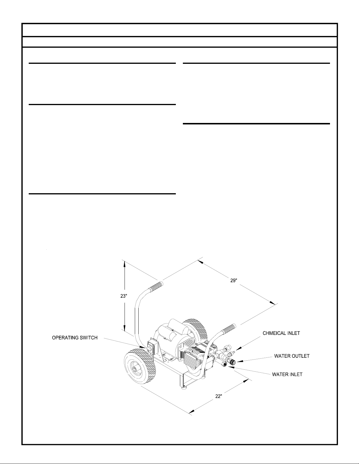
ELECTRIC DRIVEN COLD WATER CLEANER
FLUSHING
1. Connect machine to an electrically grounded
circuit that is fuse or circuit breaker
protected.
2. Connect machine to a pressurized water supply
meeting the requirements specified in the
GENERAL section of the MODEL
SPECIFICATIONS.
3. Turn on the water supply.
4. Check the float tank (if so equipped) to assure
it is full and the float valve shuts off securely.
5. Check the position of the ball valve (if so
equipped) on outlet line of the float tank
assuring it is in the open position.
6. Remove spray tip from gun assembly.
7. With gun assembly in hand, turn on the pump
switch. On trigger gun models hold the trigger
gun valve in open position.
CAUTION: DO NOT RUN PUMP WITHOUT
WATER, AS THIS WILL CAUSE DAMAGE TO
THE PUMP AND VOID WARRANTY.
8. When clean water flows from gun, turn off the
switch.
9. Reinstall spray tip.
10. With gun assembly in hand, turn on the switch.
On trigger gun models hold the trigger gun valve
in open position.
11. When clean water flows from gun, turn off the
pump switch.
12. If freezing conditions may exist, refer to
“STORAGE” section.
13. Turn off and disconnect the water supply.
Disconnect electrical supply.
STORAGE
1. Rinse the Soap Line by inserting the screen into
a container of clear water and open the metering
valve 1 minute to clean it of any remaining
residue. Be sure the chemical metering valve
is closed when finished.
2. Disconnect the water supply.
3. Remove the spray tip nozzle from gun
assembly and wire to machine.
4. Check the position of the ball valve (if so
equipped) on the outlet of the float tank
assuring it is in the closed position.
5. Attach an air chuck to the air valve stem on the
pump assembly. With the trigger gun in the open
position, apply air until a mixture of air and
very little water is coming from the gun wand
6. Fill a 1-gallon container with Ethylene Glycol
type antifreeze. Minimum should be a mixture
of ½ antifreeze and ½ water strength before each
use, as the antifreeze will dilute with each use.
7. Install a 2-ft. Garden hose to the water inlet.
Insert the other end into a container of
antifreeze solution.
8. With the discharge gun assembly in hand, turn
on the switch. On trigger gun models hold the
trigger gun valve in open position.
9. Turn off the switch just prior to running out of
antifreeze mixture.
10. Disconnect electrical supply.
11. Disconnect gun and hose.
12. Place machine in a dry place protected from
weather conditions.
SPRAY TIP
1. Remove the spray tip from the gun assembly.
2. Blow out debris with compressed air from the
outside in. Any debris remaining in the inlet
side of the nozzle should be cleaned out. If lime
or chemical scale is present in the inlet side,
the nozzle may be soaked in descaling solution
or replaced. If the tip is worn, replace with one
specified in the GENERAL section of MODEL
SPECIFICATIONS or MODEL EXPLODED
VIEW.
3. Before replacing spray tip flush the machine per
“FLUSHING”.
4. Reinstall Spray tip to gun assembly.
BELT TENSION
DEFLECTION
SPAN
1. Correct belt tension will allow a 1/64-inch
deflection for each inch of span between pulley
centers with a 6-pound force applied in the
middle of the span.
EXAMPLE: A 6-pound force applied at the
middle of an 8 inch span should produce a
deflection of 8/64 inch or 1/8 inch.
2. Belts can be tightened or loosened by loosening
the nuts holding the pump assembly to the
motor mount. Then tighten or loosen the j-bolt
on the motor mount. Retighten the pump
assembly after the desired tension is reached.
11-21-03 Z08-02783
ECN-03022 Supersedes 02-16-01 Z08-02783 7