ALKOTA 4142 User manual

P.O. Box 288 105 Broad Street Alcester, SD 57001
800.255.6823 www.alkota.com
OLD VALUES. NEW IDEAS.
4142


02-01-07 Z08-01291
PUMP ........................................................................P/N N07-00016
PUMP PULLEY.................................................................R03-00774
PUMP PULLEY BUSHING...............................................R04-00001
PUMP TYPE..............GENERAL CERMAIC PLUNGER, OIL BATH
UNLOADER...............................................................P/N C07-03700
MOTOR HORSEPOWER........................................... 4 HP / 3.0 KW
MOTOR SPEED…………….............................................1694 RPM
MOTOR VOLTAGE............................................. / 230V 60HZ 1PH
MOTOR PART NUMBER.............................................F02-00088-U
MOTOR PULLEY...........................................................R03-00139
MACHINE VOLTAGE.............................................230V 60HZ 1PH
CURRENT……....................................................................20 AMP
CAM SWITCH.........................................................P/N F04-00743
BURNER PART NUMBER........................................... V00-17367-2
BURNER TYPE......................................... PRESSURE ATOMIZING
FUEL TYPE.......................................................#1 OR #2 FUELOIL
FUEL PRESSURE................................................ 125PSI / 8.6 BAR
FUEL NOZZLE.....................(2.50 80 DEGREE B) P/N V2.50 80DB
FUEL CONSUMPTION...............................2.75 GPHR / 10.4 LPHR
FUEL PUMP..................................(DAN FOSS) P/N V-100714-001
BURNER
ELECTRICAL
PUMP MOTOR
PUMP & UNLOADER
MODEL 4142
SPECIFICATIONS
DISCHARGE VOLUME......................................4.0 GPM / 15.1 LPM
PUMP HEAD PRESSURE................................1400 PSI / 96.5 BAR
TEMPERATURE RISE.........150°F @ 4.0 GPM / 65°C @ 15.1 LPM
COMBUSTION SMOKE/BACHARACH SCALE..#1 OR #2 SMOKE
CARBON MONOXIDE ALLOWED.......................................... 0.01%
DRAFT/STACK INSTALLATION........... 0.2” - 0.04” WC READING
HEAT INPUT...........................420,000 BTU/HR /105,840 KCAL/HR
MINIMUM INLET WATER PRESSURE................10 PSI / 0.68 BAR
STACK SIZE.........................................7 7/8” DIA / 203.2 MM DIA
FUEL TANK CAPACITY............................................14 GAL / 45 L
WEIGHT (DRY) ..................................................450 LBS / 204 KG
HOSE, UNLOADER TO COIL.........................................Y01-00051
SPRAY TIP.....................................(#5.5-15DEG) P/N J00-15070-2
HOSE, DISCHARGE............................3/8” X 50’ P/N K02-03150E1
BELT - MOTOR TO PUMP..................................... P/N R02-00234
COIL SIZE.........................................1/2”ID X 158’ SCHEDULE 40
REPLACEMENT COIL w/SS WRAPPER.............. P/N 4182-00207
COIL BACK PRESSURE (NEW)
..............5 PSI @ 4.0 GPM / 0.3 BAR @ 15.1 LPM
COIL BACK PRESSURE REQUIRING DESCALING
.................... 50 PSI @ 4.0 GPM / 0.3 @ 15.1 LPM
GENERAL
PERFORMANCE
PART NUMBER
4142-300000
4142-30020
IMPACT NOZZLE (STEAM OPTION).............................. J05-00345
WAND & GUN (STEAM OPTION)........................... P/N 122-00700A
TEMP CONTROL, ADJUSTABLE (OPTIONAL) .......P/N F04-00818
WAND & TRIGGER GUN......................................... P/N J06-00158-B
WAND 42”SS............................................P/N J06-00104E
TRIGGER GUN............................................P/N J06-00158
COMBINATION KIT
OPTION

x
MAINTENANCE PERFORMED
SERIAL NUMBER DATE OF PURCHASE PLACE OF PURCHASE
MONTH/ DAY/YEAR OPERATING HOURS
NOTES
06-14-06 Z08-04527
Supersedes 8-25-04 Z08-04527
MACHINE RECORD

2
OPERATION TABLE OF CONTENTS
ELECTRIC DRIVEN OIL FIRED CLEANER
SAFETY INSTRUCTIONS Page Number
•Safety Symbols 3
•General 3
•Mechanical 4
•Electrical 4
•Fuel 5
INSTALLATION
•Location 5
•Electrical 6
•ExtensionCord 6
•Venting 5
•Water Supply 5
•Barrier 5
•WaterConditions 5
•Freezing 5
•Coldweather 5
•Chemicals 5
VENTING
•DraftDiverters 6, 7
•VentingInstallation Information 7
OPERATION
•PreStart-Up 7
•Start-Up 8
•ToClean,ApplyChemical, To Rinse 9
•ShutDown 9
COMBI OPERATION (OPTIONAL)
•PreStart-Up 10
•Start-Up 11
•ToClean,ApplyChemical, To Rinse 11
•ShutDown 11
MAINTENANCE
Machine
•SprayTipMaintenance 12
•BeltTension 12
•Coil Back Pressure 12
•Schedule 14
•Flushing,Storage 13
Burner
•FuelPump Screen See Parts List Section
•TransformerCheck See Parts List Section
•BurnerGunRemove/Replace See Parts List Section
•BlowerFanRemove/Replace See Parts List Section
Fuel Filter Page Number
•Maintenance See Parts List Section
TROUBLESHOOTING
•Machine 16,17
•WaterHeater 15
•OilBurner See Parts List Section
•Pump See Parts List Section
•FuelFilter See Parts List Section
SERVICE
•Pump See Parts List Section
•Fuel Filter See Parts List Section
•TriggerGun See Parts List Section
•Unloader See Parts List Section
• MachineBreakdown See Parts List Section
COMPONENT ADJUSTMENT
Burner
•Air BandAdjustment See Parts List Section
•BussBarAlignment
See Parts List Section
•ElectrodeAss’yAdjustment
See Parts List Section
Chemical Metering Valve See Parts List Section
Temperature Control (If So Equipped)
See Parts List Section
Unloader Valve See Parts List Section
WARRANTY InsideBackCover
SPECIFICATIONS InsideFrontCover
SCHEMATIC Last Page
Supersedes 08-19-05 Z08-03940TC 07-05-06 Z08-03940TC

3
SAFETY, INSTALLATION, AND OPERATION
ELECTRICAL DRIVEN OIL FIRED CLEANER
3
GENERAL SAEFTY
Supersedes 08-19-05 Z08-03940 07-05-06 Z08-03940
Read and understand this “OPERATOR’S
MANUAL” and “LABELS
ON THE MACHINE” before
starting.
WARNING: The discharge reaching over
125° F can cause SERIOUS BODILY INJURY to
you and anyone coming in contact with it.
La décharge atteignant par-dessus 125° F peut
causerLA BLESSUREPHYSIQUESERIEUSEàvous
et n'importe qui entrant le contact avec cela.
La expulsión de que es más de125°F puedo hacer
un lesión de grave a Usted o alguien quien usar
esto equipo.
1. Beforeoperating thismachine, read and observeall
safety,unpacking, and operating instructions.
Failure to comply with these instructions could
create a hazardous situation.
2. Theoperatorofthis equipment should notoperatethis
equipmentwhen fatigued or underinfluence of
alcoholor drugs.
3. The operator of this equipment should be
thoroughly familiar withits operationand trained
in the job to beaccomplished.
4. Theoperator ofthis equipment should wear
protectiveface shields andother protective
clothingas required forsafe operation.
5. Keep all protective covers and shields in place.
Operating this machine with moving parts could
allow operator or bystander serious injury or even
death.
6. Do not operate the machine if any mechanical
failure is noted or suspected. Keep all shields in
place.
7. Do not leave this machine unattended when it is
operating.
8. All installations must conform to all applicableLocal
codes. Contact your electrician, plumber, utility
company or seller for details.
9. If a water leak is found, DO NOT OPERATE THE
MACHINE. Shut off the motor and repair.
10. Follow instructions on how to stop the machine and
bleed pressures quickly. Be thoroughly familiar with
the controls.
11. When starting a job, survey the area for possible
hazardsandcorrectbeforeproceeding.
12. If chemicals are used in conjunction with this
equipment,readandfollowtheproductlabeldirections.
13. During normal operation of this machine, HOT
dischargesand surfacesmay beproduced.
MACHINE UNPACKING
ALL CLEANERS ARE CAREFULLY INSPECTED AND
CARTONED TO PROTECT AGAINST SHIPPING
DAMAGE. IFTHERE ISDAMAGEORMISSINGPARTS,
THETRANSPORTATION COMPANYAGENTSHOULD
MAKE A NOTATION TO THAT EFFECT ON THE BILL.
REFER TO THE PARTS LIST IN THIS MANUAL AND
ADVISE WHAT PARTS ARE MISSING OR DAMAGED.
IFAVAILABLE, GIVE THE INVOICE NUMBER ONALL
ORDER BILLS. THIS PROCEDURE WILL ENABLE
NEEDEDPARTS TO BESHIPPED QUICKLY.
READ ALL Installation, Operation, and Maintenance
instructionsbefore operating themachine.
NOTE:RefertoCLEANERMODELforSERIALNUMBER
location.
NOTE: Dimensionsare in inches unless otherwisenote.
The safety alert symbol. Thissymbolis used to
identify safety information about hazards that can result
inpersonal injury.
Asignalword(DANGER,WARNING,orCAUTION)isused
with the alert symbol to indicate the likelihood and the
potential severity of injury. In addition, a hazard symbol
may be used to represent the type of hazard
DANGER indicates a hazard which, if not avoided,
will result in death or serious injury.
WARNING indicatesa hazard which, if notavoided,
could result in death or serious injury.
CAUTION indicatesa hazard which, if notavoided,
might result in minor or moderate injury.
CAUTION, when used without the alert symbol,
indicates a situation that could result in damage to
the equipment.
IMPORTANT SAFETY
INSTRUCTIONS

4
18. Do not start the machine unless the gun assembly
isfirmly grippedby the machine operator. Failureto
do this could result in injury from flying hose and
gunassembly.
1. Allguards, shields,and covers must be
replacedafteradjustmentsaremadeto
prevent accidental contact with
hazardousparts.
2. Drivebelts must be inspectedandtightened through
out to operate at optimum levels.
3. Inspect machine for damaged or worn components
andrepair or replacetoavoid potential hazards. Do
notoperate the machine if anymechanical failure is
notedor suspected.
4. Always use the correct size spray tip specified in
the GENERAL section of the MODEL
SPECIFICATIONS orMODEL EXPLODED VIEW.
1. Thismachine must beelectrically grounded. Failure
to have the machine grounded may result in the
operatorbeingelectrically shocked and evendeath.
2. Do not plug-in or un-plug machine with wet hands.
3. Keeppower cords andconnections(connectors) out
ofwater.
4. If an extension cord must be used to operate this
machine, it should be as short as possible. The
extensioncordmustbeproperlysizedandfittedwith
agrounding type plug and receptacle.
5. All wiring and electrical connections should comply
with the National Electrical Code (NEC) and with
barcodesand practices.
6. Fusesor circuitbreakers should be compatible with
machinerequirements. (See ELECTRICAL section
ofMODELSPECIFICATIONSforposerrequirements)
7. High voltage may be present within this machine.
Servicing should only be performed by properly
trainedpersonnel.
14 .Alwaysshut down machine before refueling.
15 .Do not overfill the fuel tank. If any spillage occurs,
cleanup immediatelyand/orneutralizethespillbefore
attemptingto operate the machine.
16 .Always point the gun assembly in a safe direction
and do not direct spray on the cleaner.
17. Do not start the burner unless a full flow of water is
comingfromthe wand. Air leaks orinsufficientwater
to the machine means less than full flow of water
through the coil. This could cause hose failure and
burnsto the operator.
4
Supersedes 08-19-05 Z08-03940A 07-05-06 Z08-03940A
ELECTRICAL SAFETY
MECHANICAL SAFETY
WARNING: OPEN FLAME. Do not operate
this machine in an area with combustible
materials. A suitable fire extinguisher should
beavailableinoperatingarea.
FLAMMEOUVERTE.Nepasfonctionnercette
machine dans un secteur avec les matériels
combustibles. Un extincteur d'incendie
convenabledoitêtredisponibledansl'opération
desecteur.
ADVERTENCIA: LLAMA ABIERTA. No
funcione esta máquina en un área con los
materiales combustibles. Un extintor
conveniente debe estar disponible en área
defuncionamiento.
WARNING:ELECTRICAL SHOCKHAZARD
LEDANGER ELECTRIQUE DE CHOC
ADVERTENCIA:CHOQUEELÉCTRICO
WARNING: RISK OF INJECTION OR
SEVERE INJURY. KEEP CLEAR OF
NOZZLE.DONOTDIRECTDISCHARGE
STREAM AT PERSONS. THIS
EQUIPMENT IS TO BE USED ONLY BY
TRAINEDOPERATORS.
AVERTISSEMENT:RISQUED’INJECTIONET
DEBLESSURESGRAVES. SETENIRÀL’ÉCART
DUJET. NEPASDIRIGERLEJETDE SOTIEVERS
D’AUTRESPERSONNESCONFIERL’UTILISATION
LEJETDESOTIEVERSD’AUTRESPERSONNES.
CONFIERL’UTILISATION DE CEMATÉRIELÀUN
OPÉRATEURQUALIFIÉ.
ADVERTENCIA:RIESGODELAINYECCIÓN
O SEVERO LESIÓN. CLARO DE LA
SUBSISTENCIA DEL INYECTOR. NO DIRIJA LA
CORRIENTEDELADESCARGA EN LAS PERSO-
NAS. ESTO EL EQUIPO DEBE SER UTILIZADO
SOLAMENTELOSOPERADORESENTRENADOS.

5
1. Useonlyfuel#1or#2diesel. Theuseofincorrectfuel
mayresultin fire orexplosionand severe injurytothe
operator.
2. Donotrefuel machine while itisrunningor hot. Allow
it to cool sufficiently to prevent ignition of any spilled
fuel.Clean up any spilled fuel before resuming
operation.
3. Fuelburning equipment must have properventilation
for cooling, combustion air, and exhausting of
combustionproducts.
4. Stacking, where required, must be installed in
accordance with all local codes.A draft diverter must
be installed on a machine connected to an exhaust
stacktoprevent improper operation.
5. Where stacking is not required, provide adequate
ventilations to prevent any possible accumulation of
hazardousfumes.
6. Personnel trained in and familiar with the type of
equipment being serviced should only perform
adjustmentstofuelburningequipment.
SAVE THESE SAFETY
INSTRUCTIONS
1. LOCATION: This machine should be installed by
only qualified technicians. The machine should be
setupon a level surface whereit will notbe affected
by strong winds, rain, snow, extreme heat, and
freezing temperatures. Install the machine
considering locations for chemical pick-up, fuel
connections,electrical connections, water hook-up,
venting,andmaintenance.
All wiring and electrical connections should comply
withtheNationalElectricalCode(NEC)andwithlocal
codesand practices. Usethechart on thenext page
foryour cord selection
5
2. WATERCONDITIONS: Localwaterconditionsaffect
the coil adversely more than any other element. In
areaswheretroublesome conditions may existwith
like equipment (such as water heaters), we
recommendthe use of a watersoftener.
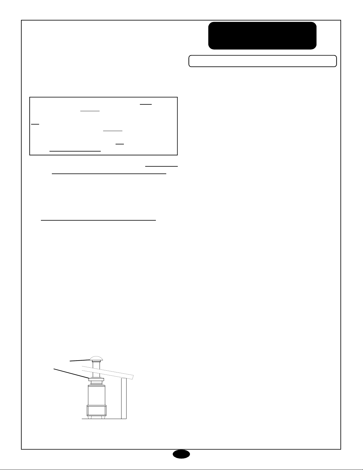
3. VENTING: This machine emits carbon monoxide, a
deadlygas,andmustbeventedifusedinanenclosed
area. Improperventingcan cause poor combustion,
delayed ignition, down drafts, and the possibility of
freezing the coil. Contact your distributor or local
heating and air conditioning dealer for proper
materials.Localcodes must beobserved.
4. WATER SUPPLY: This machine must have a water
supplymeetingorexceedingthemaximumdischarge
volume and a minimum water inlet pressure of 10
PSI/ 0.68 BAR.
5. BARRIER: We recommend a barrier be installed
between the machine and wash area to prevent
moisturefromcoming in direct contactwithelectrical
controls,motorsandtransformers. This will increase
themachine’s lifeand lessen electrical problems.
6. FREEZING: This machine must be protected from
freezingaccordingtoSTORAGEsectionofMACHINE
MAINTENANCE.
7. COLD WEATHER: As the weather becomes colder,
fuel becomes thicker and may become so viscous
that the fuel will not flow properly. As viscosity
increases,the thicker oilcan cause delayedignition,
poorspraypatterns, and rumbling fires. Asmoisture
will quickly destroy fuel pumps, make certain that
tankopeningsare secure andmoisturecannot enter.
Incold weather areas, frost buildup will occurin fuel
tanks.Asthe weather warms itturnsto condensate,
andthe water willbe in thetank. Keep the tankclear
of water, as moisture reaching the fuel pump will
cause rust, and the pump will bind. A full fuel tank
will lessen condensation build up.
8. CHEMICALS: Mix chemicals per the chemical
manufacturersprinted directions. Follow all mixing,
handling, application, and disposal instructions.
Weargloves,boots, goggles, and protectiveclothing
appropriatefor the chemicalbeing used.
INSTALLATION
Supersedes 08-19-05 Z08-03940B 07-05-06 Z08-03940B
WARNING: DO NOT USE GASOLINE,
CRANKCASEDRAININGS, OROIL CONTAINING
GASOLINE OR SOLVENTS.
AVERTISSEMENT: NE PAS UTILISER
D’ESSENCE DE PRODUITS DE VIDANGE NI
D’HUILE CONTENANT DE L’ESSENCE OU DES
SOLVANTS
ADVERTENCIA: NO UTILICE LA GASOLINA, EL
CÁRTERDEL MOTORDRAININGS, O ELACEITE
QUECONTIENE LAGASOLINA O SOLVENTES.
FUEL SAFETY
WARNING:CARBONMONOXIDEHAZARD
AVERTISSEMENT: MONOXYDE DE
CARBONE
ADVERTENCIA:MONÓXIDO DE CARBONO

6
9. ELECTRICAL: Connect machineto an electrically
grounded circuit that is fused or circuit breaker
protected. The circuit must match that specified in
the ELECTRICAL section under MODEL
SPECIFICATION.
10. EXTENSION CORD: Theuse of anextension cord
that has undersize wire compared to the amp draw
ofyour machine will adversely limitthe starting load
carrying abilities of the motor and machines
performance. Use only 3-wire extension cords that
have3-prongplugs and 3-polecordconnectors that
accepttheplug from theproduct. Useonlyextension
cords that are intended for outdoor use. These
extension cords are identified by a marking
“Acceptable for use with outdoor appliances; store
indoors while not in use.” Use only extension cords
havingan electricalrating not less than therating of
theproduct. Do notuse damaged extension cords.
Usean extension cordingood repair freeoffrays or
cracksintheouter covering. Do not abuseextension
cord and do not yank on any cord to disconnect.
Keepcordaway from heat andsharpedges. Always
disconnect the extension cord from the receptacle
beforedisconnectingtheproductfromtheextension
cord.
11. THREEPHASE INSTALLATION: Threephasepower
must be connected so that the motor has clockwise
rotation as you look at the shaft end of the motor.
WATER INSTALLATION
1. WATER TEMPERATURE VARIATION: On
machines not equipped with a temperature control
device, the temperature of the discharged water is
dependanton the incomingwatertemperature.Some
minor adjustmenttothe fuel inputmaybe required if
the incoming water is significantlY different than 50
degreesfahrenheit.
2. WATERCONDITIONS:Localwater conditions affect
thecoil andspray tip more adversely thanany other
element.Inareaswheretroublesome conditions may
exist with like equipment (such as water heaters),
werecommend theuse of a water softener.
WARNING: Thismachine emits carbon monoxide,
and deadly gas, and must be vented if used in an
enclosed area. Improper venting can cause poor
combustion, delayed ignition, down drafts, and the
possibilityoffreezingthe coil. Contact yourdistributor
orlocalheatingandair conditioning dealer for proper
materials. Local codes must be observed.
The information contained herein is offered for
reference only. You must comply with local codes
and investigate through your gas and other utility
companies when installing, as there may be some
special local requirements you must comply with.
AlsoseeANSIZ223.
1. DRAFT DIVERTERS:(STACKEDCLEANERS)
Oilfiredmachinesuseaforceairburner.Theoilburner
canbeinfluencedby“NaturalDraft”eventhoughthey
havetheirown fan. A Belltype draft divertermustbe
usedhere also.
A. Adraftdivertermustbe used on all cleaners that
are stacked. This includes any chimney even if
not expelled to the outside.
6
Supersedes 08-19-05 Z08-03940C 07-05-06 Z08-03940C
WARNING:ELECTRICAL SHOCKHAZARD
LEDANGER ELECTRIQUE DE CHOC
ADVERTENCIA:CHOQUEELÉCTRICO
CHART FIGURES ARE BASED ON NOT MORE
THAN100FOOT.
(BasedonAmbientTemperature of 86°F (30°C)).
*UseAmp Draw indicated the same or higher than your
machineoutput
EXAMPLE: MachineAmpDraw51,use55(2Conductor).
The thermostat type of cord shall be C, PD, E, EO, EN,
S, SO, SRD, SJ, SJO, SV, SVO, SP.
The thermo set plastic types shall be ET, ETT, ETLB,
ETP,ST, STO, SRDT, SJT, SJTO, SVT, SVTO,andSPTB.
COPPER WIRE
SIZE
MINIMUM AWG
16
15
14
12
10
8
6
4
2
MACHINE AMP
DRAW*
3 CONDUCTOR
WIRES
10
—
15
20
25
35
45
60
80
MACHINE AMP
DRAW*
2 CONDUCTOR
WIRES
13
—
18
25
30
40
55
70
95
VENTING
WARNING: CARBON MONOXIDE HAZARD
DANGER
MONOXYDEDE CARBONE
MONÓXIDO DE CARBONO
PELIGRO

7
1. The first time the machine is operated, after repairs
havebeenmade,orifthemachinehassetforaperiod
of time (30 days or more) follow the following
procedures.
A. Checkthetensionofthebelt (if so equipped) per
instructionsin MACHINE MAINTENANCE.
B. Flushthe machine per instructions inMACHINE
MAINTENANCE.
C. Install float tank drain plug (if so equipped).
D. Openfloat tank ballvalve (if soequipped).
2. CAUTION: Always use the factory supplied wash
hose with your machine. Do not substitute other
hosesas apotential safety problem may develop.
CAUTION: If machine has been exposed
to sub-freezingtemperatures, it must be thoroughly
warmedtoabove freezingbeforeoperating.Failureto
warm machine can cause damage to the pump
packingsand other components.
Read and observe all items in “CLEANER
INSTALLATION”.
♦SPRAY TIP: Choose the correct spray tip for the job
tobeperformed.
♦OIL LEVEL: Check the oil level in the water pump.
♦BELT: Make sure belt tension and condition is as
specifiedin MACHINE MAINTENANCE.
♦STACK COVER: Remove the stack cover (if so
equipped).
♦FUELFILTER: Inspectfuelfilterforevidenceofwater
contaminants.
♦FUEL: Makesurethefuellinesareopen(CAUTION:
Closed valves will DAMAGE the fuel pump and void
warranty). Use #1 or #2 diesel.
♦FUEL QUANTITY: Make sure the fuel supply is
sufficient to complete the job. See the GENERAL
sectionofMODEL SPECIFICATIONSforthefueltank
capacity.
♦Refer to the MAINTENANCE SCHEDULE for any
maintenancetobeperformed before operationofthis
machine.
7
Supersedes 08-19-05 Z08-03940D 07-05-06 Z08-03940D
B. Use a draft diverter of the inverted funnel or bell
type that meets all codes for capacity and
materials. Mount the draft diverter directly to
thestacking flangeon themachine.
C. The draft diverter’s function is to insure that the
barometric pressures are as close to the same
as possible at the air inlet and outlet to the coil
and will not be changed by either up drafts or
downdrafts.
D. Installation of a draft diverter WILL NOT
PREVENT THE COIL FROM FREEZING. In
areas where freezing temperatures are
common, some type of down draft prevention
mustbeused. Checklocalcodesforacceptable
methodsforthe prevention of downdrafts.
2. VENTINGINSTALLATION INFORMATION:
A. Never Reduce the Stack size. The diverter and
stacking should be the same size as the stack
openingon the machine.
B. Straight Stacking through the roof is preferred.
Horizontalrunsarenotdesirable,butifnecessary,
be sure to pitch the stack upward at a rate of
two inches per foot. When horizontal stacks
areused, verticalstacking must extend at least
twofeet forevery foot of horizontal stack.
C. Stack Extension above the roofline should be
sufficientto clear the peak ofthe roof. (Refer to
ANSIZ223.1page 100 ofSPECIFICS)
D. ARainCapU.L.approvedshouldbeinstalledon
the stack.
OIL OR GAS FIRED MACHINES ARE NOT TO BE
CONNECTEDTOA TYPE BGAS VENT.
NE PAS RACCORDER CET APPAREIL À UN TUYAU
D’ÉVACUATION DE GAZ DU TYPEB.
MÁQUINA DE ACIETEO GASES NO SERCONECTADO
CON A MECANOGRAFÍE B RESPIRADERO DEL GAS.
PRE START-UP
Vent/RainCap
Diverter
OPERATING
INSTRUCTIONS

8
CAUTION: A good flow of water must be flowing
from the end of a gun for 30 seconds, before
proceeding. Lackofwater can cause damagetothe
waterpump and like components.
CAUTION: On a machine equipped with a trigger
gunvalve, ifthetriggergunvalveremainsintheclosed
positionfor more than3minutes,water pumpdamage
may occur.
3. Turn the switch to the “burner” position.
CAUTION: Do not run the machine with the burner
switchin the onposition when thefuel tank isempty
or with tank valves closed.This will cause damage
to the fuel pump and void warranty.
CAUTION: Donotoperatewiththetriggergunvalve
closed for more than 3 minutes or water pump
damagemay occur.
8
START-UP
Supersedes 08-19-05 Z08-03940E 07-05-06 Z08-03940E
Quick-Connect spray tips have fixed spray patterns that
are more consistent than those produced by an adjustable
nozzle.Eachtipiscolor-codedforeasyidentification.White
(40°): produces a wide-fan spray for general cleaning and
rinsing.Green(25°): provides anarrower-fansprayfortough
stainsin general cleaningapplications. Yellow (15°): main-
tainsatight-fanspraywithintensecleaningpowerforheavy-
duty cleaning and paint preparation. Red (0°): creates a
concentrated pinpoint water jet for stubborn stains on con-
crete, masonry, or steel, and for stripping paint.
♦ELECTRICAL: Connect the machine to an electrically
groundedcircuitthatisfuseor circuitbreaker protected.
Do not use any type of adapter. If the correct type of
receptacle is not available, have one installed by a
qualified electrician.
♦WATER SUPPLY: This machine must have a water
supply meeting or exceeding the maximum discharge
volumespecified inthe PERFORMANCE section, and
a minimum water inlet pressure of 40 PSI / 0.68 BAR.
♦LIME:Watercontaininglargeamountsoflime, calcium
orother similar materials can producea coating onthe
inside of the spray tip, impact nozzle and coil pipe.
♦FLOAT TANK: Check the float tank (if so equipped) to
assure it is full and the float valve shuts off securely.
♦FLOAT TANK BALL VALVE: Check the positionof the
ball valve on the outlet side of the float tank (if so
equipped) that it is in the open position
♦CHEMICAL: Use factory recommended chemicals for
bestcleaning action and forextendedpump life. Follow
instructions on chemical container.
1. Selecttemperature (if soequipped).
2. With the gun assembly in hand (on trigger gun models
hold the trigger gun valve in open position) and with a
goodflowofwaterturntheswitchtothe“pump”position.
WARNING:ELECTRICAL SHOCKHAZARD
LEDANGER ELECTRIQUE DE CHOC
ADVERTENCIA:CHOQUEELÉCTRICO
WARNING: RISK OF INJECTION OR
SEVERE INJURY. KEEP CLEAR OF
NOZZLE.DONOTDIRECTDISCHARGE STREAM
ATPERSONS. THISEQUIPMENTISTO BE USED
ONLYBY TRAINED OPERATORS.
AVERTISSEMENT:RISQUED’INJECTIONET
DE BLESSURES GRAVES. SE TENIR À
L’ÉCART DU JET. NE PAS DIRIGER LE JET DE
SOTIEVERS D’AUTRES PERSONNESCONFIER
L’UTILISATIONLEJETDESOTIEVERSD’AUTRES
PERSONNES. CONFIER L’UTILISATION DE CE
MATÉRIELÀ UN OPÉRATEUR QUALIFIÉ.
ADVERTENCIA:RIESGODELAINYECCIÓN
O SEVERO LESIÓN. CLARO DE LA
SUBSISTENCIA DEL INYECTOR. NO DIRIJA LA
CORRIENTEDELADESCARGA EN LAS PERSO-
NAS. ESTO EL EQUIPO DEBE SER UTILIZADO
SOLAMENTELOSOPERADORESENTRENADOS.
WARNING: Use of pressure washer can create puddles
and slippery surfaces.
High pressure spray could cause you to fall if you are
too close to the cleaning surface.
• Keep spray nozzle between 8 to 24 inches away from
cleaning surface.
• Operate this unit on a stable surface.
• The cleaning area should have adequate slopes and
drainage to reduce the possibility of a fall due to slippery
surfaces.
• Be extremely careful if you must use the pressure
washer from a ladder, scaffolding or any other relatively
unstable location.
• Firmly grasp spray gun with both hands when using high
pressure spray to avoid injury when gun kicks back.

9
9
Supersedes 08-19-05 Z08-03940F 07-05-06 Z08-03940F
TO RINSE:
A. Close the chemical metering valve buy turning
clockwise.If the gun assemblyis equipped with adual
lancewand open thevalve.
NOTE: It is advisable to dip the chemical screen in a
container of clean water and open the valve 1 minute
toclean the valve of anyremaining residue.
B. If the gun assembly is equipped with variable or
multiple nozzle assembly, open and close to clean
nozzle of any remaining residue.
C. After a clear flow of water is noted from the end of
thewand, Engage thetrigger safety latchon the spray
wand. Pull back the Quick-Connect collar on the end
of the wand and remove the tip. Now insert high
pressuretip into the fitting, andrelease the collar.start
from the top, working downward using long,
overlappingstrokes.
NOTE: Machines with PRESSURE SWITCHES,
because of lower pressures may lose heat during
soaping.
1. Turn theswitchtothe“pump”position. (Ifnot already
done so in the cold water rinse.)
2. After cool, clear water is coming from the end of the
wand, turn switch to the “off” position .
3. Turn off the water supply.
4. If freezing conditions may exist, refer to STORAGE
inMACHINEMAINTENANCE.
5. Replacestack cover (ifso equipped).
CAUTION: You cannot draw an abrasive product such
as an aluminum brightner. It will cause an
non-warrantable premature pump failure.
TO CLEAN:
A. Startonthelowerportionoftheareatobecleaned
andworkupusinglong,even,overlappingstrokes.
B. Dirtis generally removedeasily if greaseand/or
oilare notpresent. However if grease and/oroil
are present, hot water and chemical will
accelerate in the cleaning process.
4. TOAPPLY CHEMICAL:
Upstream Chemical Injection
When injecting chemicals “upstream” what you are do-
ingis introducing chemicalsto the waterflowas it enters
theactualpumpinletandrequiresa float tank. The popu-
larity of this type of chemical injection is due to the fact
thatthis allowschemicals to be applied atfull pressure
amajoradvantageforproductivity.
Downstream Chemical Injection
Mounted to the outlet of the pump or the coil a down-
stream injector introduces chemicals to the water flow
AFTER it leaves the pump or the coil. This effectively
eliminates the major risks of exposing the inner work-
ings of a pump to harsh chemicals. When chemical is
desired, the system must be switched over to the low
pressure nozzle to draw chemical.
A. Engagethe trigger safetylatchon the spraywand.
Pull back the Quick-Connect collar on the end of the
wand and remove the tip. Now insert “black” tip into the
fitting, and release the collar. You can draw chemical
only with the “black” low pressure nozzle.Tug on spray
tip to make sure the connection is secure. Rotate to
desired spray angle. For most effective cleaning, keep
spray tip from 8 to 24 inches away from the cleaning
surface.
B. Insert chemical screen into chemical container.
C. Turn the burner switch to the “off” postion.
There will be air in the chemical line. Air heats very
quicklyandneedstobeeliminated before the burner can
beturnedon.Openthemetering valve counter clockwise
withthe triggergun openallowing the chemical to come
upthe chemicalline. Chemical should begin movingup
the chemical line. Once the chemical line is completely
full, trigger the gun on and off numerous times to break
any possible air locks. Turn burner system switch to
“on”position.
D. If the gun assembly is equipped with variable or
multiple nozzle assembly, adjust to low pressure.
E. If the gun assembly is equipped with a dual lance
wandopenthe valve.
Do not allow the detergent to dry on the surface
(preventsstreaking).
SHUT-DOWN

10
NOTE: In process of making steam, the water flow
through the coil has to be decreased. The amount of
water is determined by the pressure and water
temperature of your location.
If the incoming water temperature is as high as 70°F,
the amount of water going through the coil has to
decrease very little.
If the incoming water temperature is as low as 40°F,
the amount of water going through the coil has to be
decreased.
The water temperature is relative to the season
variation and should be taken in consideration when
operating steam.
The 2 systems used to create steam they are the high
volume and low volume system. The high volume
system uses a regulating valve and the low volume
uses a metering valve.
1. Set temperature control at 300°F / 150°C
MAXIMUM.
2. Open the water bypass ball valve (if so equipped)
on the coil inlet assembly.
TEMPERATURE REGULATING:
Regulate the temperature indicated on the
thermometer to 300°F by adjusting the regulating
valve.
3. Turn the tee on the regulating valve (if so equipped)
clockwise to DECREASE the temperature and
counter clockwise to INCREASE the temperature.
1. Set temperature control at 300°F / 150°C
MAXIMUM.
2. Completely open the water bypass metering valve
(if so equipped) handle turning it counter
clockwise found on the pump or unloader
assembly.
COMBI OPTION
OPERATING INSTRUCTIONS
ELECTRIC DRIVEN OIL/GAS FIRED
OPEN CLOSED
BALL VALVE POSITION
PRESTART-UP
HIGH VOLUME COMBI
PRESTART-UP
LOW VOLUME COMBI
g g OPEN
CLOSED g g
05-26-06 Z08-05465
DECREASE
TEMPERATURE
CLOCKWISE g g
g g INCREASE
TEMPERATURE
COUNTER CLOCKWISE
PRESSURE
REGULATING
VALVE
WARNING: The discharge reaching over 300°
F can cause SERIOUS BODILY INJURY to you
and anyone coming in contact with it.
La décharge atteignant par-dessus 300° F peut
causer LA BLESSURE PHYSIQUE SERIEUSE à
vous et n'importe qui entrant le contact avec cela.
La expulsión de que es más de300°F puedo
hacer un lesión de grave a Usted o alguien quien
usar esto equipo.
WARNING: RISK OF INJECTION OR
SEVERE INJURY. KEEP CLEAR OF
NOZZLE. DO NOT DIRECT DISCHARGE
STREAM AT PERSONS. THIS EQUIPMENT IS
TO BE USED ONLY BY TRAINED OPERATORS.
AVERTISSEMENT:RISQUE D’INJECTION
ETDE BLESSURESGRAVES. SE TENIR À
L’ÉCART DU JET. NE PAS DIRIGER LE JET DE
SOTIEVERSD’AUTRESPERSONNESCONFIER
L’UTILISATION LE JET DE SOTIE VERS
D’AUTRES PERSONNES. CONFIER
L’UTILISATION DE CE MATÉRIEL À UN
OPÉRATEURQUALIFIÉ.
ADVERTENCIA:RIESGODELAINYECCIÓN
O SEVERO LESIÓN. CLARO DE LA
SUBSISTENCIA DEL INYECTOR. NO DIRIJA LA
CORRIENTE DE LA DESCARGA EN LAS PER-
SONAS. ESTO EL EQUIPO DEBE SER
UTILIZADO SOLAMENTE LOS
OPERADORESENTRENADOS.

11
OPEN CLOSED
BALL VALVE POSITION
3. With a small common screw driver turn the screw
on the metering valve (if so equipped) counter
clockwise to DECREASE the
temperature and clockwise to
INCREASE the temperature.
1. Install the open gun assembly.
2. With the gun assembly in hand (on trigger gun models
hold the trigger gun valve in open position) and with a
good flow of water, turn the switch to “pump” position.
CAUTION: A good flow of water must be flowing from
the end of a gun for 30 seconds, before proceeding.
Lack of water can cause damage to the water pump
and like components.
CAUTION: Ona machineequipped witha triggergun
valve, if the trigger gun valve remains in the closed
positionformore than 3 minutes,waterpump damage
may occur.
3. Turn the switch to the “burner” position
CAUTION: Do not run the machine with the burner
switch in the on position when the fuel tank is empty
or with tank valves closed. This will cause damage to
the fuel pump and void warranty.
CAUTION: Do not operate with the trigger gun valve
closedfor more than3 minutes orwaterpumpdamage
may occur.
4. To CLEAN:
A. Start on the lower portion of the area to be cleaned
and work up using long, even, overlapping strokes.
B. Dirt is generally removed easily if grease and/or oil
is not present. However if grease and/or oil are
present, hot water and chemical will accelerate in the
cleaning process.
5. TO APPLY CHEMICAL:
CHEMICAL: Usefactory recommended chemicals for
best cleaning action and for extended pump life.
Contact your dealer for chemicals available. Follow
instructions on chemical container.
Note : If the valve is open without the chemical line
in a source the water pump willdraw air causing the
system not to pressure up.
Mix chemicals per label instructions. Use necessary
safety percautions.
When chemical is desired, the system must be
switched over to the low pressure nozzle to draw
chemical.
A. Insert chemical screen into chemical container.
B. If your system is hot water turn theburner switch
to the off postion. There will be air in the soap line.
Air heats very quickly and needs to be eliminated
before the burner can be turned on. Open, counter
clockwisethe soap meteringvalve toup the chemical
line. Once the chemical line is completely full trigger
control gun. Soap should begin moving up the
chemicalline. Oncethechemicallineis completelyfull
trigger, the gun on and off numerous times to break
any possible air locks. Turn burner system switch to
“on” position if equipped.
C. Adjust metering valve or injector. Install your
injector tip.
D. If the gun assembly is equipped with variable or
multiple nozzle assembly, adjust to low pressure .
5. To Rinse: (For cold water rinse, turn the burner
switch off.)
A. If the machine is equipped with a panel mounted
metering valve, close the chemical metering valve.
NOTE: It is advisable to dip the chemical screen in a
container of clean water and open the valve 1 minute
to clean the valve of any remaining residue.
B. If the gun and wand is equipped with variable or
multiple nozzle assembly, open and close to clean
nozzle of any remaining residue.
C. After a clear flow of water is noted from the end of
thewand, start fromthe top,working downward using
long, overlapping strokes.
1. Turn the burner switch to the “off” position. (If not
already done so in the cold water rinse.)
2. After cool, clear water is coming from the end of the
wand, turn the switch to “off” position.
HIGH VOLUME COMBI:
A. Close the water bypass ball
valve (if so equipped) on the coil
inlet assembly.
LOW VOLUME COMBI:
A.Completely Close thewater bypass meteringvalve
(if so equipped) handle turning it clockwise found on
the pump assembly.
3. Turn off the water supply.
4. Iffreezing conditions mayexist,
refertoSTORAGEinthesection
of MACHINE MAINTENANCE.
5. Replace stack cover (if so
equipped)
05-26-06 Z08-05465A
SHUT-DOWN
OPEN g g
CLOSED g g
START-UP
gDECREASE
TEMPERATURE
g
gINCREASE
TEMPERATURE
SCREW
CAUTION: You cannot draw an abrasive product such
as an aluminum brightner. It will cause an
non-warrantable premature pump failure.

12
1. Deflection for each inch of span between pulley
centers with a 6-pound force applied in the middle
of the span.
EXAMPLE: A 6-pound force applied at the middle
of an 8 inch span should produce a deflection of
8/64 inch or 1/8 inch.
2. Belts can be tightened or loosened by loosening
the nuts holding the pump assembly to the motor
mount.Thentightenorloosenthej-boltonthemotor
mount. Retighten the pump assembly after the
desired tension is reached.
1. Remove the spray tip from the gun assembly.
2. Blowout debriswithcompressedairfromtheoutside
in. Any debris remaining in the inlet side of the
nozzle should be cleaned out. If lime or chemical
scale is present in the inlet side, the nozzle may
be soaked in descaling solution or replaced. If the
tip is worn, replace with one specified in the
GENERAL section of MODEL SPECIFICATIONS
orMODEL EXPLODED VIEW.
3. Before replacing spray tip flush the machine per
“FLUSHING”.
4. Reinstall Spray tip to gun assembly.
A regular maintenance schedule for descaling your
heating coil is essential to insure its longevity.
The frequency of descaling depends upon the amount
of use and the condition of the water.
06-21-06 Z08-02809
Aboveis across section view showing the progressive
liming of coils.
COIL BACK PRESSURE CHECK INSTRUCTIONS
1. Check the condition of your water pump unloader
valve. Remove the hose and gun assembly from
the coil outlet.
2. Remove any flow restrictions, such as guns and
hoses, from the coil outlet.
3. Install a pressure gauge between the water pump
and coil inlet.
4. Turn on the water supply. Check the float valve (if
so equipped) to assure float tank is full and the
float valve shuts off securely.
5. Check the position of the ball valve (if so equipped)
on the outlet line of the float tank assuring it is in
the open position.
6. Turnon the switchto the “PUMP”position. Ifthe coil
back pressure reading is above that found in the
chart above then your machine needs to be
descaled.
A separate descaling pump is recommended so scale
and other chemicals will not come in contact with your
waterpump and causespremature wear.
NOTE: Contactyour localdealer fordescaling of your
machine.
7. Disconnect the water supply.
8. Disconnect the electrical supply.
9. Reinstall the hose and gun assembly.
10. Remove the pressure gauge.
DescalingInstructions areavailable upon request, ask
for part number Z08-00493.
MACHINE
MAINTENANCE
Electric Driven Oil Fired Machine
DEFLECTION
SPAN
x
SPRAY TIP MAINTENANCE
COIL BACK PRESSURE CHECK
BELT TENSION
50PSI
75PSI
100PSI
150PSI
175PSI
DISCHARGE VOLUME
GALLONS PER MINUTE/
LITERS PER MINUTE
2-3 GPM/ 7.6-11.4 LPM
3-4 GPM/11.4-15.1 LPM
4-5 GPM/15.1-18.9 LPM
6 GPM/ 22.7 LPM
8-10 GPM/ 30.3-37.9 LPM
BACK PRESSURE
REQUIRING DESCALING
USEA1000PSIPRESSUREGAUGE
Supersedes 08-15-03 Z08-02809

13
1. Rinsethe chemical lineby insertingthe screen into
a container of clear water and open the metering
valve1 minute toclean it ofany remaining residue.
Besurethe chemical meteringvalveisclosedwhen
finished.
2. Checktheposition of theballvalve (if soequipped)
on the outlet of the float tank assuring it is in the
closedposition.
3. Attach an air chuck to the air valve stem on the
pump assembly. With the trigger gun in the open
position, apply air until a mixture of air and very
little water is coming from the gun wand Then turn
switch to the “BURNER” position and depress the
vacuumswitch. Runit for45 secondsallowing any
remaining water to turn to steam.Allow air to blow
for 60 seconds. Turn switch to the “OFF” position.
4. Removethe air chuck.
5. Fill a 1-gallon container with Ethylene Glycol type
antifreeze. Minimum should be a mixture of ½
antifreeze and ½ water strength before each use,
as the antifreeze will dilute with use.
6. FLOAT TANK EQUIPPED: Pour the anti-freeze
solution into the float tank.
7. WITHOUTFLOATTANK:Installa 2-ft.Gardenhose
to the water inlet. Insert the other end into a
containerof antifreeze solution.
8. Turn on the switch to the “PUMP” position.
9. Turn off the switch just prior to running out of
antifreezemixture.
10. Disconnect electrical supply.
11 Fill the fuel tank with kerosene or #1 or #2 diesel.
12 It is recommended to install a coil cover to keep
coilfree ofdebris
13 Drain the float tank.
14 Placemachineinadryplaceprotectedfromweather
condition.
PART NO. DESCRIPTION
Y02-00001 …….....0-1000 PSI (69 BAR) Pressure Gauge
NOTE: All Gauges are Glycerin Filled ¼ NPT
Z01-00070-1…….3/8” x 100 Yards Thread Tape
1. Connect machine to an electrically grounded
circuit that is fuse or circuit breaker protected.
2. Connect machine to a pressurized water supply
meetingtherequirementsspecifiedintheGENERAL
section of the MODEL SPECIFICATIONS.
3. Turnon the watersupply.
4. Check the float tank (if so equipped) to assure it is
fulland the floatvalve shutsoff securely.
5. Checktheposition of theballvalve (if soequipped)
on outlet line of the float tank assuring it is in the
openposition.
6. Removespray tip from gun assembly.
7. With the gun assembly in hand (on trigger gun
modelshold thetrigger gun valve in open position)
and with a good flow of water turn switch to the
PUMPposition
CAUTION: A good flow of water must be flowing
from the end of a gun within 30 seconds, before
proceeding. Lack of water can cause water pump
damage.
CAUTION:DONOTRUNPUMPWITHOUTWATER,
AS THIS WILL CAUSE DAMAGE TO THE PUMP
ANDVOIDWARRANTY.
OPEN CLOSED
BALL VALVE POSITION
x06-21-06 Z08-02810
ACCESSORIES
FLUSHING
STORAGE
WARNING:ELECTRICAL SHOCKHAZARD
LEDANGERELECTRIQUEDE CHOC
ADVERTENCIA:CHOQUE ELÉCTRICO
CAUTION: On a machine equipped with a trigger
gun valve, if the trigger gun valve remains in the
closedposition formorethan5minutes,waterpump
damagemay occur.
Supersedes 08-15-03 Z08-02810

14
MOTOR DRIVEN OIL FIRED CLEANERS
OIL BATH WATER PUMP:
Oil Level - check and add as needed per PUMP
SERVICEinsert.
Oil Change- drain and refill per PUMP SERVICE
insert.
CAUTION: Used oil must be disposed into a n
enviromental safe container and brought to an oil
recycling center.
Oil contamination- Milky color indicates water.
HOSES:
Blistering, Loose Covering
Abrasion of cover exposing reinforcement.
Cuts exposing reinforcement.
BELTS:
Cracks or fraying
Belt Tension- For correct tension, see MACHINE
MAINTENANCEinsert.
FILTER-WATER:
Check water inlet hose screen for debris
Check float tank screen for debris.
LEAKS:
Check for water and buildup of scale at pipe
connections.
FUEL:
Adequate fuel supply.
FILTER-FUEL:
If contaminats are present see FUEL FILTER
insert.
Remove and Replace fuel filter per FUEL FILTER
insert.
SCREEN-FUELPUMP:
Check fuel pump screen for debris see OIL
BURNERMAINTENANCEinsert.
BURNERNozzle:
Replace nozzle as specified in BURNER section of
MODELSPECIFICATIONSorBURNERASSEMBLY
insert.
GUARDSANDSHIELDS:
Check that all guards and sheilds are in place and
secure.
PUMPMOTORWITHGREASE FITTINGS:
Remove drain plug. Use 1 or 2 full strokes of shell
“DOBLIUM RB”, Cheveron”SR1 No.2” or Texaco
“PREMIUM RB”. Operate for 20 minutes and replace
drain plug.
FREEZINGTEMPERATURES:
Freezing temperatures break coils and water
pumps. See STORAGE in theMACHINE
MAINTENANCE section for cold weather
instructions.
MACHINE MAINTENANCE SCHEDULE
Electric Driven Oil Fired Cleaners
EACH HR AFTER FIRST EVERY EVERY EVERY
DAILY 8 HRS 50 HRS 50HRS 100 HRS 500 HRS YEARLY
05-26-06 Z08-02812

15
Supersedes 07-15-03 Z08-02850 07-03-06 Z08-02850x
REMEDY
POSSIBLECAUSETROUBLE
ELECTRIC MOTOR DRIVEN PRESSURE CLEANERS
1. Poor cleaning
action.
2. Machine will
not draw
chemical.
3. Low operating
pressure.
4. Excessive,
unusual
noise.
5. Belts slipping.
A. Hard water.
B. Low pressure.
C. Little or no chemical being drawn.
D. Improper chemical.
E. Improper chemical mixture.
F. Low discharge pressure.
A. No chemical solution.
B. Metering valve not open.
C. Chemical line strainer clogged.
D. Air leak in Chemical line.
E. Metering valve clogged.
F. Restrictor orifice too large or missing.
A. Insufficient water supply.
B. Incoming water hose too small.
C. Water supply hose too long.
D. Belt slippage.
E. Worn belt.
F. Spray tip worn or wrong size.
G. Dirty or worn check valves in water
pump.
H. Water supply hose kinked.
I. Inlet filter screen clogged.
J. Motor runs slowly.
K. Air leak in inlet plumbing.
L. Defective water pump.
M. Leaking discharge hose.
N. Chemical metering valve open and
sucking air.
O. Defective unloader.
P. Inlet ball valve not fully open (if so
equipped).
Q. Restricted coil.
A. Pump.
B. Defective motor.
C. Pulleys rubbing.
D. Misalignment of pump &motor
A. Belts too lose.
B. Excessive backpressure.
C. Defective water pump.
A. Connect the machine to a water softener.
B. See “Low operating pressure.”
C. See “machine will not draw chemical.”
D. Obtain proper chemical.
E. Mix chemical per the label. Follow all the mixing,
handling, application, and disposal instructions.
F. See “Low operating pressure.”
A. Replenish supply.
B. Turn metering valve knob to open.
C. Remove screen and cleaan.
D. Tighten all fittings and hoses for the chemical line.
E. Disassemble and clean.
F. Install proper size orifice.
A. The water supply must meet or exceed the
maximum discharge volume specified in the
PERFORMANCE section, and minimum water inlet
pressure specified in the General section of the
MODELSPECIFICATIONSsection.
B. Use larger water supply hose.
C. Use shorter water supply hose.
D. Tighten belt per instructions in MACHINE
MAINTENANCE insert.
E. Replacebelt per CLEANER EXPLODED VIEW.
F. Replace with spray tip specified in the GENERAL
sectionof MODEL SPECIFICATIONS.
G. SeePUMPTROUBLE SHOOTING.
H. Straighten hose.
I. Clean water filter screen or hose inlet screen.
J. See “Pump engine starts slow or overheats and
stops.”
K. Tighten all fittings.
L. SeePUMP TROUBLESHOOTING.
M. If a water leak is found, DO NOT OPERATE THE
MACHINE. Disconnect the power and replace
hose.
N. Refill chemical, place soap screen in water, or
shut off metering valve.
O. Repair or replace unloader valve.
P. Open inlet ball valve completely. (Handle parallel w/
valvebody).
Q. See COIL BACK PRESSURE CHECK on MACHINE
MAINTENANCE.
A. SeePUMPTROUBLESHOOTING.
B. Call service technician or take engine to Reapir/
Warranty station.
C. Adjust shields or pulley(s).
D. Realign pump and engine.
A. Tightenper instructionon MACHINE MAINTENANCE.
B. See “Excessive Back Pressure” Below
C. SeePUMP SERVICE.
CLEANER TROUBLESHOOTING

16
Supersedes 07-15-03 Z08-02850 07-03-06 Z08-02850A
A. Spray tip built up with lime.
B. Water pump turning too fast.
C. Coil built up with lime.
D. Relief valve defective.
A. Defective belt.
B. Defective Pump.
C. Defective accumulator.
A. No power.
B. Defective motor starter or ON
OFF switch.
C. Defective motor.
A. Pump frozen
B. Defective Motor.
C. Defective water pump
D. Excessive backpressure.
A. Low voltage.
B. Excessive backpressure.
C. Defective motor.
A. Motor starter “kicked out” (if so
equipped) or thermal overload
tripped.
B. Excessive backpressure.
C. Defective motor.
A. Incoming voltage incorrect.
B. Not large enough extension
cord.
C. Too long extension cord.
A. Machine improperly grounded.
B. Outlet not grounded.
A. Remove and clean, or replace spray tip with tip specified
inGENERAL section ofMODEL SPECIFCATIONS.
B. SeeMODEL SPECIFICATIONS.
C. Delime Coil.
D. Remove and replace.
A. Remove and replace using belt specified in
CLEANEREXPLODED VIEW or the GENERAL section of
MODELSPECIFICATIONS.
B. SeePUMP TROUBLESHOOTING.
C. Recharge/replace.
A. Use a different outlet, check fuses in main disconnect
switch. Replace fuse if blown.
B. Call service technician.
C. Call service technician, or take motor to repair. Warranty
station.
A. Machine must be thoroughly warmed to above freezing.
B. Call service technician or take motor to Repair/ Warranty
station.
C. See PUMP STATION.
D. See “Excessive Back Pressure.”
A. See “Low voltage.”
B. See “Excessive Back Pressure.”
C. Call service technician, or take motor to Repair/Warranty
station.
A. Turn motor starter off to reset, and then turn on, or push
thermal overload reset button on motor.
B. See “Excessive Back Pressure.”
C. Call service technician, or take motor to Repair/ Warranty
station.
A. Have a qualified technician check motor terminal voltage.
Correct voltage is in MODELSPECIFICATIONS.
B. Use an extension cord with amperes or watts rating as
high or higher than that of the MODEL SPECIFICATIONS.
C. Shorten extension cord.
A. STOP! Operating machine. Call Service technician.
B. Have properly wired outlet installed.
CLEANER TROUBLESHOOTING (CONT.)
ELECTRIC MOTOR DRIVEN PRESSURE CLEANERS
TROUBLE POSSIBLECAUSE REMEDY
6. Excessive back
pressure.
7. Excessive
vibration.
8. Pump motor will
not start (motor
does not hum).
9. Pump motor will
not start (motor
hums).
10. Pump motor
starts slow or
overheats and
stops.
11. Pump motor
stops and will not
start.
12. Low voltage.
13. Machine shocks
operator.

17
Supersedes 07-15-03 Z08-00133 07-03-06 Z08-00133
1. Machine will not rise to
operatingtemperature.
2. Machine overheats
3. Machine Smokes
4. Machine fumes
(exhaust
burns eyes)
5. Excessive oil dripping
from laydown coil
condensate.
6.PoorCombustion
7. Dry Steam (very little
moisture, veryhot
steam)
A. Low fuel pressure
B. Poor combustion
C.Fuel filter clogged
D. Temperature control
inoperative
E. Improper fuel supply.
F. Water in the piping.
A. Insufficient water
B.Temperature control
inoperative
C. Improper fuel supply.
A. Improper fuel supply.
B. Clogged or improper burner
nozzles.
C. Loose burner nozzle.
D. Insufficient combustion air.
A. Improper fuel pressure
B. Too munch combustion air.
A. Incorrect burner nozzle.
B. Burner nozzle defective.
C. Loose nozzle.
D. Fuel pressure too high.
A. Low fuel pressure
B. Improper fuel supply
C. Insufficient combustion air.
A. Insufficient water.
B. Improper fuel supply.
C. Improper fuel pressure
A.Fuelpressure shouldbeat125PSI/8.6BAR.
B. See “Poor Combustion”.
C. Remove and replace filter element per
FUEL FILTER INSERT.
D. See the TEMPERATURE CONTROL
section.
E. Use #1 or #2 diesel.
F. Drain fuel tank and remove, and replace
filter element per FUEL FILTER INSERT.
A. SeeLowOperating Pressure on MACHINE
TROUBLE SHOOTING INSERT.
B. See the TEMPERATURE CONTROL
section.
C. Use fuel specified in “BURNER” section of
the MODEL SPECIFICATIONS.
A. Use #1 or #2 diesel.
B. Remove and replace with appropriate
nozzle found on the MACHINE
SPECIFICATIONS.
C. See BURNER MAINTANCE INSERT.
D. See AIR BAND ADJUSTMENT section
on OIL BURNER MAINTANCE.
A. FuelPressure should be125PSI/ 8.6 BAR.
B. See BURNER TROUBLESHOOTING
INSERT.
A. Replace nozzle with one found in
specification page per burner. Nozzle
replacement on BURNER MAINTANCE
page.
B.Replace nozzle with one found in
specification page per burner. Nozzle
replacement on BURNER MAINTANCE
page.
C. Tightenper Burner Nozzle Replacement in
BURNER MAINTANCE section.
D. See FUEL PRESSURE ADJUSTMENT
sectiononBURNERMAINTANCE INSERT.
A. FuelPressure should be125PSI/ 8.6 BAR.
B. FuelPressure should be125PSI/ 8.6 BAR.
C. See AIR BAND ADJUSTMENT section in
OIL BURNER MAINTANCE.
A. SeeLowOperating Pressure on MACHINE
TROUBLE SHOOTING INSERT.
B. Use #1 or #2 diesel.
C. FuelPressure should be125 PSI/ 8.6BAR.
TROUBLE POSSIBLECAUSE REMEDY
OIL WATER HEATER TROUBLESHOOTING
Table of contents
Other ALKOTA Pressure Washer manuals