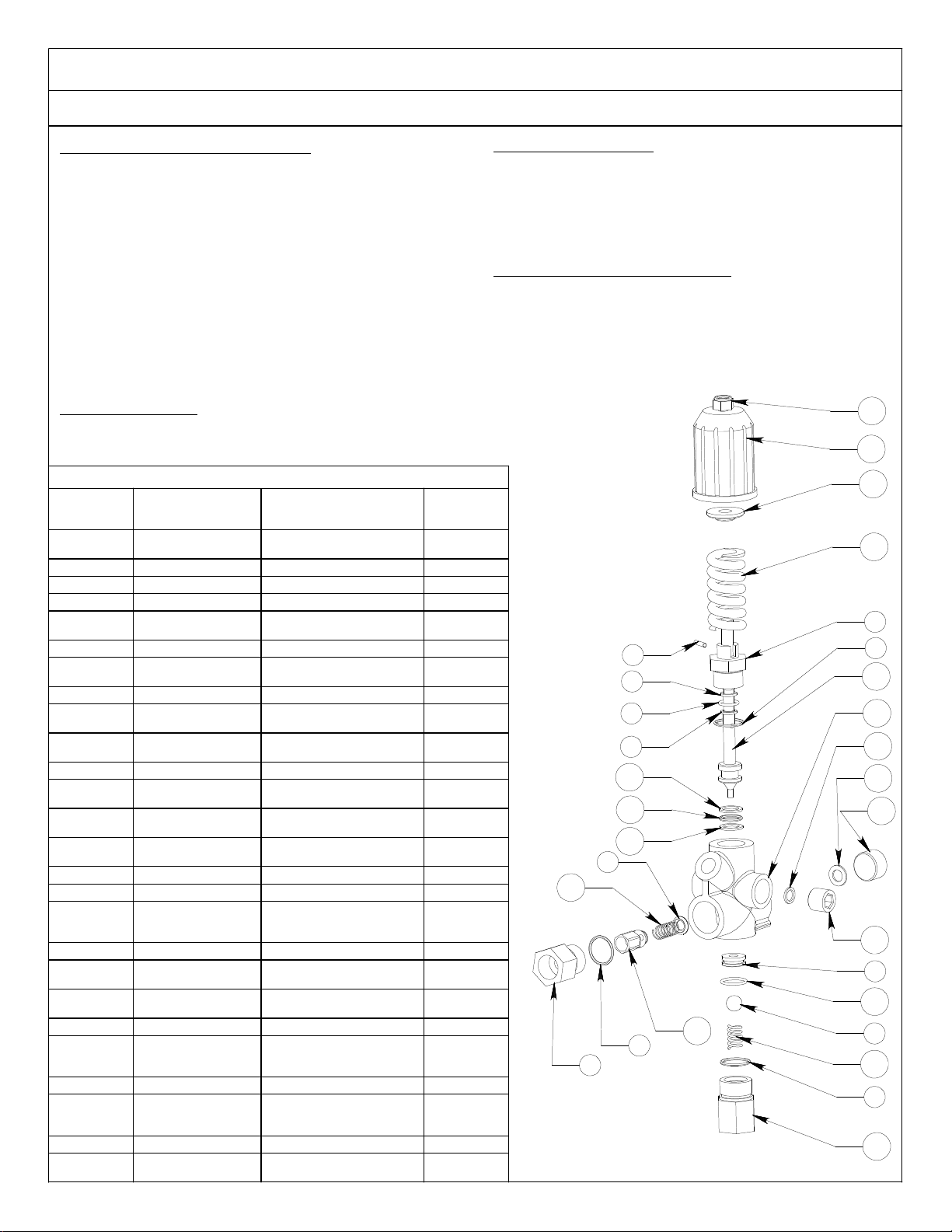
ALKOTA 2142 User manual

P.O. Box 288 105 Broad Street Alcester, SD 57001
800.255.6823 www.alkota.com
OLD VALUES. NEW IDEAS.
2142

SERIAL NUMBER DATE OF
PURCHASE PLACE OF PURCHASE
MONTH / DAY / YEAR OPERATING
HOURS MAINTENANCE PERFORMED
MACHINE RECORD
Supersedes 01-08-04 Z08-04527 08-25-04 Z08-04527
NOTES

£os~a-soz96-Z~
(g2)£OB~o-BOZ '(6~)(BI)(LI)(vl)Llv20-BOZ "~S UN.OP>lO~J8Jo.= .! 318V::>'311 ~200o-203 ~l
2tl2 1300Vi'lV::>3GI Vt6~Ol-~00 BZ i 3Nl1 dVOS ')'lBI'i3SSV ~060o-021v t~-
dOl 110::>')'lBI'i3SS't I. O~~00-~21~ LZ i 0131HS).3110d 'lN31'i013M OS~Oo-~21~ £L
~VI ~,~S -nv~~ ~~~SVMx~~ 'M~~~, tnt~l-vn~ ~1 ~~n' 'InN ~nn~1-~n~ ~~
(O2008-2v~2) IH~IV~lS -~3NV31::> 'Ai18~3SSV 00900-~vl~ ~z- dV::>'M3~3S 000~2-vOH ~I
(OOO08-Zvl~) ~3~~1~1 -~3NV31::> ')'18~3SSV £O90o-~vIZ ~l- O~O::>'~3~NVH 8d~OB~o-BI8V 01
S~OOONI31V~3dOION 00 ~NIN~VM 'lV::>30 £LvOO-IOO tl OI~SNON'3dVl 002vo-90Z 6
~o,o::> II1n~ 3dl~IS/M V1O~lV "VJ30 VO~vOO-~OO£Z 3A1VA~3I31'i 'lV::>30 V£6000-100 B
)'V~dS 'dil l-gZ£Ogl-oor ~l ~38~ON1VI~3S 'lVJ30 VIOOOo-lOO L
H38Bn~ '13~1'iO~ IgvOO-vOj ~l V31H3WNNI 30~ 'lV::>30 VZ6000-IOO 9
3dlHIS ~010::>Il101'i 'lV::>30 V6SLIO-IOO OZ 310NVH'dl~~ aIOOO-lOZ ~
03110::>'3SOH OILOo-lO~l 61- ~NIN~VM~NVI 1303 'lVJ30 ZlvOo-lOO v
NO~~ ONVM'A18~3SSV V~OLOO-Zt~Z aI- ~NIN~VM-H3~NVO 'lVJ30 VB600o-l00 £
Sdl~~ ~ ONVM'A181'i3SSV VOOLOO-Zvl~ LI- 3).3S1108 'lV::>30 V60vOo-lOO Z
3S0H 'd~V13 ££OOO-~OM91 H111li 'nV~ vBOOo-l07 I
NO11dl~S3a 'ON l~d 311 ' NO11dl~S3a 'ON l~Vd ~11
.LSI7 S.Lb'/7'd
9':~~~~
~=!-~
£OS~d-90Z 96-Z~ L£I~O-HO
OeOO8-efrl'e 'OOOO8-efr'l'e N/o'
.Lepre -EJNIEJt7'.>IJt7'd :Lb'3SNI


9£og~-gOZg~O 99ZLO-~O
1331S '~NlddV~1S LO-LOOOo-tOZ tt ~I~ ONV3~11 'A18~3SSV SOOOO-lO~ ZZ
ONV8'dl1J Lo-rOoOO-tOl tt ~3N~n8 'A18~3SSV OOtOO-ltLZ Ll
OOOM'1311Vd 9L9l0-l0l It ~JO1 '1nN OOSL£-90H Ol
OL OL Lt ~31VM '3SOH OOLLO-09~ 6L
OL Ol Ot 3S0H 'd~V1J IrOOO-lOM BL
1VNI~~31 '~01V1nSNI 9L900-t03 ~£ ~~V11VO1J 'A18~3SSV VLlLOO-lZLZ LL
)JI1dS 'lVNI~~31 SL900-tOJ g£ ~JO1 '1nN OO£L£-90H 9L'
3311)~ NIV~1S '~NIHSn8 IltOO-tOJ L£ 13NVd 10~1NOJ 'A18~)SSV lO£OO-lSS£ SL
318VJ ')11 V-£lOOO-lOJ 9£ r '1108 ZO£L£-£OH tl
3dld 'lIOJ LOlOO-llLl ~£ NV~~3NNI1 '1nN 900~l-90H £L
NV~~3NNI1 'dl1J lLOSl-90H -t£ A '1138 II-LltOO-lO~ lL
dVJ 'M3~JS lOO~Z-tOH ££ d~nd 'A18~3SSV OO~OO-ltLl LL
~381J JI~V~3J 'NOl1V1nSNI £tO~O-LOZ Z£ ~~OJ 'lYNI~~31 OL900-tOJ OL
~381J JI~V~3J 'NOl1V1nSNI 6LLOO-O6 L£ A 31~NIS 'A311nd l£IOO-£O~ 6
3~V~J '1N3~O13M O£LOO-l~gr O£ JI~1J313 '~01~ 9BOOO-lOJ 9
NV~~3NNI1 'd11J LLOSZ-90H 6l dYJ 'M3~JS 90£l£-tOH L
3dld '~n1d Z-tOOOO-603 9Z 3S0H 'd~V1J ££OOO-ZOM 9
)SOH '8~V8 6LOOl-ZOM Ll a1V~8A10d ')SOH Z-£l9LO-LOZ S
JI1SV1d -d~V1J ')SOH d-££OOO-lOM 9l 3dld '31ddiN l-OLOOO-tL3 t
alV~8AlOd ')SOH Z-£lZ£O-LOZ 5Z J3113~ '3A1VA 60g00-£OJ £
~388n~-'1)~O~~ £StOO-tOJ tl 3dld '331 Z-£000O-Ol3 l
1Vd 'InN OOSZ9-90H £Z 3S0H 3S1nd 'A18~3SSV OtOOO-LOA I
NOILdl~~S3a 'ON L~Vd ~3LI NOlidl~~S3a 'ON i~Vd ~3il
.LSI7 S.Lb't7'd
0O900-cp Jc -b'3NtJ'37..7 A 7BN3SStJ'

9S9ZO-S0Z9&-10
~nnJVA 'HJ1IMS 19LOO-vO3 ~l 9l ~ -~OlJI~lS3~ lt~Ol-Zlt JL
3dld '31dd1N Z-OLOOO-£L3 vL t/L -~OlJI~lS3~ 90~OL-OZL 8L
3dld '~NIHSn8 l-~OOOo-tO3 £L JI1SVld -Z£ 6 ~~11Jn~lS3~ lt~Ol-~t9 VL
3S0H '8~V8 ~ZOOL-ZOM ZL _NOIIV~1113 'N33~JS OZLOO-tOJ 9
1311no 3015 'MO813 Z-£LOOO-BO3 II 3S0H '~3HSVM lLlOo-~O~ g
3dld '31ddiN Z-OLOOO-~l3 OL 13AIMS '~31dVOV v9l0o-g0J t
3dld '~nld d-ZOOOO-603 6 3SOHN30~V~ 'lnN l-OLZOO-~O~ £
~NVllVOlj 'lN3~a13M OZltO-ZZlZ 8B 3dld '~NlldnOJ Z-vOOOO-903 Z
~NVllVOlj 'lN3~013M OlltO-Zvlv VB lVOlj '3A1VA l£900-£O~ L
NOI~dl~~S3a 'ON ~~Vd ~3~1 NOILdl~~S3a 'ON L~Vd ~3LI
.LSI7 S.Lb'l7'd
tZLLD-ZgB£ 'LZLlO-ZtLZ 'LZLLO-ZZLZ NO3sn -8B
lZllO-ltZ NO3sn -VB
lZllO-ZtZ NO3sn -JL
lZllO-ZZlZ 'lZllO-ZtlZ NO3sn -8L 1,,-;
,
lZllO-l~B£ NO3sn -VL ,;
t,;
~'\
N!'
9S9ZO-S0Z9&-10 69910-110
1"8'1"1"0-8'9S£ '1"8'1"1"0-8'PI"8' '1"8'1"1"0-8'8'1"8' '1"8'1"1"0-8'P8' N/d -/13
NI7t7 b'3t7t7Ib'.L ->lNI7'.L .L17'07-::1 ~ 7BN3SSI7'


ASSEMBL }-: PUMP -P IV 2.142-00500 2.142-0050.1
DR--QO685 Supercedes10-96ZO8-QI804 04-98 ZO8-01804
PARTS LIST -500
ITEM PART NO, DESCRIPTION ITEM PART NO, DESCRIPTION
1 CO3-00810 VALVE,AIR 8 R03-00669 PULLEY SINGLE-V
2 E04-00002-2 BUSHING.PIPE 9 HO5-31304 WASHER,LOCK
3 E10-00003-2 TEE. PIPE 10 N07-20048 SCREW.CAP
4 EO4-00003-2 BUSHING.PIPE 11 N07-31046 MOUNT,PUMP
5 EI3-00010-2 NIPPLE. PIPE 12 E14-o0010-2 NIPPLE. PIPE
*6 N07-00026 PUMP,WATER-TT941 13 WO2-10022 BARB,HOSE
7 R04-o0001 BUSHING,PULLEY 14 W02-10017 BARB.HOSE
*For breakdown see Z08-01807
OR-o1668
PARTS LIST -50.1
'TEM PART NO, DESCRIPTION ITEM PART NO, DESCRIPTION
1 W02-10022 BARB.HOSE 11 K33-01200 HOSE,WATER
2 E04-o0003-2 BUSHING.PIPE *12 N07-00026 PUMP.WATER-TT941
3 W02-10017 BARB.HOSE 13 R04-00001 BUSHING.PULLEY
4 W02-10021 BARB.HOSE 14 R03-o0669 PULLEY,SINGLE-V
5 W02-00032 CLAMP,HOSE 15 H05-31304 WASHER.LOCK
6 E14-o0010-2 NIPPLE PIPE 16 N07-20048 SCREWCAP
.7 C07-03700 VALVE UNLOADER 17 N07-31046 MOUNT.PUMP
8 E08-00010-2 ELBOWPIPE 18 EI3-00015-2 NIPPLE. PIPE
9 E04-00002-2 BUSHING.PIPE 19 E08-00027-2 ELBOW,REDUCINGPIPE
10 CO3-00810 VALVE AIR 20 E10-00004-2 SIDE OUTLETPIPE
*For breakdown see Z08-02643(7). Z08-01807(12) 0~8 ZO8-01804

08-19-05 Z08-02643
SPECIFICATIONS
MAXIMUM FLOW....................................................... 7.8 GPM / 30 LPM
MAX UNLOADING PRESSURE.............................. 3650 PSI / 251 BAR
MAXIMUM TEMPERATURE ................................... UP TO 190°F / 88°C
WEIGHT....................................................................... 2.1 LBS / 0.91 KG
BYPASS..................................................................................... 1/4 FNPT
INLET & DISCHARGE............................................................... 3/8 FNPT
REPAIR PARTS PACKAGE
*C07-03700K - Includes 1 of item #1, 1 of item #2, 1 of item #3,
3 of item #4, 2 of item #7, 2 of item #13,
1 of item# 14, 1 of item# 27
UNLOADING ADJUSTMENT
1. Install an appropriate pressure gauge in pump head outlet.
The gauge should have a range twice the operating pressure.
2. Loosen nut (Item 19) and turn the knob (Item 20) counter
clockwiseuntil minimum spring tension.
3. Open the trigger gun, start the pump, and observe
pressure gauge reading.Slowly tighten the knobclockwise
until the desired pressure.
4. Close and open the trigger gun to check unloading
pressure and bypass function of the unloader valve.
The unloading pressure should not exceed operating
pressure more than 400 PSI.
5. Lock the setting by tightening the nut (item 19).
NOTE: Once the operating pressure is reached,
turning the knob clockwise will increase the
unloading pressure only.
ACCESSORIES
Y02-00009............................................... 0 TO 1500 PSI / 103 BAR GAUGE
Y02-00002............................................... 0 TO 2000 PSI / 138 BAR GAUGE
Y02-00010............................................... 0 TO 5000 PSI / 345 BAR GAUGE
Supersedes 04-29-03 Z08-02634
PART LISTS
ITEM PART
NUMBER PART DESCRIPTION QTY.
18RS6-000SV01 O-RING - 1/16CS X
1/2ID 1
2C07-02000-18 BALL, SS 11/32 1
3C07-02000-20 O-RING 1
4C07-02300-08 O-RING - 11/16 ID 3
5C07-03700-1 FITTING, OUTLET - 3/8 1
6C07-03700-11 GUIDE PISTON 1
7C07-03700-12 RING,
ANTI-EXTRUSION 2
8C07-03700-15 PIN, ROLL 1
9C07-03700-21 GUIDE, PISTON - SS 1
10 C07-03700-23 SPRING,
COMPRESSION 1
12 C07-03700-26 PISTON 1
13 C07-03700-28 RING,
ANTI-EXTRUSION 2
14 C07-03700-29 O-RING - 3/32 X 7/16ID
X 3043 1
15 C07-03700-3 SPRING,
COMPRESSION 1
16 C07-03700-4 ORIFICE, SHUTTER 1
17 C07-03700-6A PLUG,, 3/8NPT 2
18 C07-03700-6B GASKET, WASHER -
1/16CS X 5/16 X
7/16OD 2
19 C07-03700-7 NUT, NY-LOCK 1
20 C07-03700-8 KNOB, ADJUSTMENT 1
21 C07-03700-9 FOLLOWER, SPRING 1
22 C07-0370010C SPRING, BLUE 1
23 C07-0370018B HOUSING, UNLOADER
- 3/8FNPT 1
24 C07-0370019A PLUG 1
25 C07-0370019B GASKET, WASHER -
1/16CS X 5/16ID X
9/16OD 1
26 C07-03800-24 GUIDE, BALL 1
27 N07-20028 O-RING - 1/16CS X
7/16ID 1
20
21
22
6
4
12
13
14
13
23
18
17
9
27
2
10
4
26
3
15
16
4
5
8
19
7
1
7
25
24
*
*
*
*
*
*
*
**
*
**
*
*
AL606
VALVE, UNLOADER - BLUE SPRING 3650 PSI
BREAKDOWN - P/N C07-03700

.0810-80l 96-01
£1 L0810-80l ' L 18l10-80Z aas uMOp~DaJqJOj. 3SOH 8~V8 c £lOOI-lOM II
-3dld 131100 3015 l-tOOOO-013 Il MIV '3A1VA 01800-fOJ 01
Jdld ~NI~003M 'MO813 l-LlOOO-803 Ol 3dld '~NIHS08 l-lOOOO-t03 6
3dld J1ddiN l-~1000-fI3 61 3dld'MO813 l-01000-R03 R
d"Od '1NOO" 9tOlf-LON RI M30V01NO'3A1VA 000lO-LO3 If
~_. dV~ 'M3~~S -8~00l-LON LI 3dld '31dd1N l-01000-tI3 9
~301 'MJHSVM tOrlr-~OH 91 3S0H 'dNN1~ lfOOO-lOM ~
A-31~NIS 'A3110d 69900-rOM ~I 3S0H '8MV8 IlOOI-lOM t
.
A3110d '~NIHS08 10000-tOM tl 3S0H 8MV8 LIOOI-lOM f
Iv611 -~J1VM 'd~d 9l000-LON rl+ Jdld '~NIHS08 l-rOOOO-v03 l
MJ1VM'JSOH OOlIO-££~ II 3Satl '8MV8 llOOI-lOM I
NOlldl~OS3a 'ON i~Vd ~311 NOlldl~OS3a 'ON i~Vd ~311
109 -..LSI7 S..Lb'p'd
lrZlo-~a
l0910-90Z aas uMOp~DaJqJOj+
JSOH'8~V8 LIOOI-lOM vi AJ110d ~NIHS08 10000-vO~ l
JSOH'8~V8 llOOI-lOM £1 Iv611 -~J1VM 'd~Od 9l000-LON 9f
3dld 'J1ddiN l-OIOOO-vIJ II 3dld 'J1dd1N Z-OI000-£ 13 ~
d"Od '1NOO" 9tOI£-LON II 3dld '~NIHS08 l-r0000-v03 t
dV~ 'MJMJS 8tOOl-LON 01 3dld '331 l-fOOOO-013 f
>1:)01'M3H~ tOflf-~OH 6 3dld '~NIHS08 l-lOOOO-tOJ l
A-31QNIS AJllOd 69900-fOM g ~IV '3A1VA OlgOO-£O~ I
NO'id'~~S3a 'ON i~Vd ~311 NOlidl~~S30 'ON i~Vd ~3il
OOg -..LSI7 S..Lb'p'd
lfto, II
@,
.
,,§ I @ ~I
.0810-80l96-0~ tORIO-QOZS6-ZIS3p3JJ3dns ~ I~ S8900-1K)
M :g
I OgOO-t?fr It? OOgOO-t?fr It? N/ d -dN/7d /{ 7BN3SSp'

1. Install an appropriate pressure gauge in pump
5. Turn off machine.
turn screw counterclockwise. Turn knob to desired pressure.
set screw (item 1) in the end of knob. While grasping knob,
turned knob until it bottoms out, you will have to loosen
adjusting knob (Item 2) clockwise.
pressure gauge reading while slowly turning
3. Open trigger gun, start pump, and observe
2. Turn knob (item 2) counterclockwise until spring is loose.
of twice the operating pressure.
head outlet. The gauge should have a pressure range
4. Close and open trigger gun to check unloading
pressure and bypass operation with pressure not
exceeding 400 psi than the operating pressure.
NOTE: If the gauge does not reach waht is desired and you
6. Grasp knob, turn screw clockwise
until it bottoms out.

OIL LEVEL
TOOL KITS
PACKING EXTRACTION KIT - P/N Z09-00028
COMPLETE TOOL KIT - P/N Z09-00021
VALVE SERVICE
1. Remove the plugs holding the valve assemblies.
2. Remove and discard o-rings from the plugs. Clean
plugs with solvent or soap and water. Allow to
dry.
3. Using a needle nose pliers, fingers, or hook
shaped tool, remove the valve assemblies from
the head. Remove and discard the o-rings from
the valve assemblies and/or head. Examine each
valve assembly and discard damaged parts. Refer
to the ”PUMP BREAKDOWN” for part numbers
of any replacement items.
4. Clean any accumulated debris from the valve
cavities and flush with water.
5. Wash the valve assemblies in clean water and
rinse. While still wet, test each valve assembly
by sucking on the valve seat. A properly sealing
valve will allow a good vacuum to be developed
and maintained, while a malfunctioning valve will
not. Good valve assemblies should be set aside
for installation in step 7.
6. Malfunctioning valve assemblies must
be replaced.
7. Lubricate a new o-ring with the pump crankcase
oil and install into valve cavity in the head. Install
a good valve assembly into the cavity as illus-
trated.
8. Lubricate a new o-ring with pump crankcase oil
and place on a plug cleaned in step 2 above.
9. Install a plug into the pump head. Tighten plug
by hand.
10. Torque the plug to the value indicated in the
“TORQUE” section of the pump specifications.
11. Repeat steps 7 through 11 for remaining
valve assemblies.
HEAD REMOVAL
1. Remove the cap screws holding the pump head
to the crankcase. A metric tool is required for
this step. Be careful not to lose the washer on
each cap screw.
2. Remove the head by rotating the crankshaft and
tapping the head away from the crankcase with
a soft mallet. Keep rear surface of the
head parallel to the front surface of the crankcase
to prevent binding on the plungers.
3. Once the head is removed, protect the plungers
from damage.
GENERAL PUMP MAINTENANCE
07-23-03 Z08-00063
ECN-02981 Supersedes 11-14-02 Z08-00063
1
3
6
27
6

PLUNGER SERVICE
1. Remove pump head per “HEAD REMOVAL”.
2. Remove any packings and retainers left on the
plungers by pulling them straight off.
3. Examine each plunger, looking for a smooth
surface free of any scoring, cracks, or pitting.
Any defective plungers should be removed per
“PLUNGER REMOVAL”.
4. Discard and replace any defective plungers.
5. Reinstall the plunger per
“PLUNGER INSTALLATION”.
6. Reinstall head per “HEAD INSTALLATION”.
PLUNGER REMOVAL
NOTE: When the plunger screw is removed, it is
important to install new o-ring, anti-extrusion,
and copper washers.
1. Remove the plunger screw is removed, it is
important to install new o-ring, anti-extrusion,
and copper washers.
2. Remove the plunger retaining screw by turning
counterclockwise. Remove and replace copper
washer.
3. Remove and discard o-ring and anti-extrusion
ring from retainer screw.
4. Remove the plunger from the cross head and
examine it for cracks, scoring, or pitting.
5. Remove and discard copper flinger washer, clean
with solvent and allow to dry.
PLUNGER INSTALLATION
1. Install the copper flinger washer onto the cross
head.
2. Slide the plunger onto the crosshead.
3. Lubricate an o-ring with crankcase oil and install
into the groove on the plunger screw. Install the
anti-extrusion ring into the groove next to the o-
ring. Note: The o-ring should be nearest the
screw head and the anti-extrusion ring nearest
the threads.
4. Apply a drop of thread sealant to the threads of
the retainer screw.
5. Thread the plunger retainer screw into the cross
head making sure the copper flat washer is
installed onto the screw.
6. Torque the plunger retainer screw to the value
indicated in the torque section of the pump
specifications.
PACKING SERVICE
1. Remove the head per “PUMP HEAD REMOVAL”.
2. Remove any packings and female adapters left
on the plungers by pulling them straight off.
Insert proper packing extractor onto the
extractor hammer. Insert packing extractor and
tool through the packings and adapters
remaining in the head. Tighten the hammer and
remove the remaining items in the head. Remove
packings and o-rings from adapters. Discard the
o-rings and packings.
3. Clean the packing canities in the head and rinse
with clean water.
4. Clean exposed plungers. Clean male and female
adapters with soap and water and allow to dry.
5. Examine male and female adapters, discard worn
items. Trial fit the female adapters into the head
GENERAL PUMP MAINTENANCE
07-23-03 Z08-00063A
ECN-02981 Supersedes 11-14-02 Z08-00063A

GENERAL PUMP MAINTENANCE
07-23-03 Z08-00063B
ECN-02981
checking for binding or damage. Discard and
replace damaged items.
6. Lubricate packing cavities in the head and all
packings and adapters with pump crankcase oil.
7. Lay head on the bench with packing cavities up.
Install one male adapter in each cavity with the
flat side down.
8. Install one v-packing into each cavity with the
lips pointing down. A packing insertion too of
the appropriate size is recommended for this
operation.
9. Install the restop ring with the lips pointing
down.
10. Install a front female adapter into each cavity
with the flat side up. Make certain the adapter
goes all way down into the cavity.
11. Install the low pressure packing with the flat
side down.
12. Install the rear female adapter into each cavity
with the lips pointing down.
13. Lubricate o-rings with pump crankcase oil and
install one into the groove of each adapter.
14. Install one adapter and o-ring into each cavity
with the flat side up. Each adapter and o-ring
assembly should push into the head to
approximately 1/16 inch of being flush with the
surface of the head. Only hand pressure should
be required to perform this operation. This step
is VERY IMPORTANT.If the rear female adapter
does not fit almost flush, something is not
properly positioned. If a proper fit is obtained,
proceed to step 16. If a proper fit is not obtained,
remove the female adapters from the offending
cavity and reinstall items per steps 8 through
15.
15. Install head per “HEAD INSTALLATION”.
HEAD INSTALLATION
1. Prepare pump head per instructions in
“PACKING SERVICE”.
2. Rotate the plungers so the outer plungers are
projecting the same distance from the crankcase.
3. Lubricate the exposed plungers with crankcase
oil.
4. Start the head onto the plungers and using a
soft mallet, tap the head evenly until it comes in
contact with the crankcase.
5. Start the cap screws through the head and into
the crankcase. Do not forget the lock washer on
each screw.
6. Tighten all cap screws by hand.
7. Torque the cap screws to the value indicated in
the “TORQUE” section of PUMP
SPECIFICATIONS. Torque the cap screws in the
order listed below.
7
8
2
4
6
7
1
3
5
1
3
6
27
6


PUMP TROUBLESHOOTING
08-27-03 Z08-00195
ECN-02981 Supersedes 06-00 Z08-00195
TROUBLE POSSIBLE CAUSE REMEDY
1. Oil leaking in the
area of water pump
crankshaft.
A. Worn crankshaft seal.
B. Bad bearing.
C. Grooved shaft.
D. Failure of retainer o-ring
A. Remove and replace.
B. Remove and replace.
C. Remove and replace.
D. Remove and replace.
2. Excessive play on
crankshaft.
A. Defective bearings.
B. Excess shims.
A. See "Worn bearing".
B. Set up crankshaft.
3. Loud knocking in
pump.
A. Loose conecting rod screws.
B. Worn connecting rod.
C. Worn bearings.
D. Loose plunger bushing screw.
A. Tighten connecting rod screws per
PUMP SPECIFICATIONS.
B. Replace connecting rod per PUMP
MAINTENANCE.
C. Replace bearings per PUMP
MAINTENANCE.
D. Tighten plunger screw per PUMP
SPECIFICATOINS.
4. Oil leaking at the
rear portion of the
pump.
A. Damaged or improperly
installed oil gauge window
gasket.
B. Damaged or improperly
installed rear cover.
C. Oil gauge loosed.
D. Rear cover screws loose.
E. Pump overfilled with oil,
displaced through crankcase
breather hole in oil
cap/dipstick.
A. Replace gasket or o-ring.
B. Replace gasket or o-ring.
C. Tighten oil gauge.
D. Tighten rear screws. to torque
values in PUMP SPECIFCATIONS. S
E. Drain oil: refill to recommended oil
level as stated in OIL LEVEL in PUMP
MAINTENANCE.
5. Water in crankcase A. May be caused by humid air
condensing into water inside
the crankcase.
B. Worn or damaged plunger
screw o-ring.
A. Maintain or step up lubrication
schedule.
B. Remove and replace. See PLUNGER
SERVICE in PUMP MAINTENANCE.
6. Worn bearing A. Excessive belt tension.
B. Oil contamination.
A. See BELT TENSION in MACHINE
MAINTENANCE.
B. Check oil type and change intervals
per PUMP SPECIFICATIONS.
7. Short bearing life A. Excessive belt tension.
B. Misalignment between pump
and motor.
C. Oil has not been changed on
regular basis.
A. See BELT TENSION in MACHINE
MAINTENANCE.
B. Re-align pump and motor.
C. Check oil type and change intervals
per PUMP SPECIFICATIONS.
8. Short seal life A. Damaged plunger bushing.
B. Worn connecting rod.
C. Excess pressure beyond the
pump's maximum rating.
D. High water temperature.
A. Replace punger bushing.
B. Peplace connecting rod.
C. Match pressure stated in PUMP
SPECIFICATIONS.
D. Lower water tempersture stated in
PUMP SPECIFCATIONS.

PUMP TROUBLESHOOTING
08-27-03 Z08-00195A
ECN-02981
TROUBLE POSSIBLE CAUSE REMEDY
9. Dirty or worn check
valves.
A. Normal wear.
B. Debris
A. Remove and replace.
B. Check for lack of water inlet screens.
10. Presence of metal
particles during oil
change.
A. Failure of internal component.
B. New pump.
A. Remove and disassemble to find
probable cause.
B. New pumps have machine fillings and
debris and should be drained and
refilled per PUMP SPECIFICATIONS.
11. Water leakage from
under head.
A. Worn packing.
B. Cracked/scored plunger.
C. Failure of plunger retainer
o-ring.
A. Install new packing.
B. Remove and replace plunger.
C. Remove and replace plunger retainer
o-ring.
12. Loud knocking
noise
in pump
A. Pulley loose on crankshaft.
B. Defective bearing.
C. Worn connecting rod.
D. Worn crankshaft.
E. Worn crosshead.
A. Check key and tighten set screw.
B. Remove and replace bearing.
C. Remove and replace connecting rod.
D. Remove and replace crankshaft.
E. Remove and replace crosshead.
13. Frequent or
premature failure of
the packing
A. Scored, damaged, or worn
plunger.
B. Overpressure to inlet manifold.
C. Abrasive material in the fluid
being pumped.
D. Excessive pressure and or
temperature of fluid being
pumped.
E. Over pressure of pumps.
F. Running pump dry.
A. Remove and replace plungers.
B. Reduce inlet pressure.
C. Install proper filtration on pump inlet
pumping.
D. Check pressures and fluid inlet
temperature; be sure they are within
specified range.
E. Reduce pressure.
F. Do not run pump without water.
14. Low Pressure A. Dirty or worn check valves.
B. Worn packing.
C. Belt slipping.
D. Improperly sized spray tip or
nozzle.
E. Inlet filter screen is clogged.
F. Pitted valves.
A. Clean/Replace check valves.
B. Remove and replace packing.
C. See BELT TENSION in MACHINE
MAINTENANCE.
D. See MACHINE SPECIFICATIONS for
specified spray tip or nozzle.
E. Clean inlet filter screen.
F. See VALVE SERVICE in PUMP
MAINTENANCE.
15. Erratic pressure:
pump runs rough
A. Dirty or worn check valves.
B. Foreign particles in valve
assemblies.
C. High inlet water temperature
A. Clean/Replace check valves.
C. See temperature in PUMP
SPECIFICATIONS.
16. Excessive vibration A. Dirty or worn check valves A. See "Dirty or worn check valves"
17. Scored plungers A. Abrasive material in fluid being
pumped.
A. Install proper filtration on pump inlet
plumbing
18. Pitted plungers A. Cavitation A. Decrease inlet water temperature
and/or increase inlet water pressure.
19. Cavitation A. High inlet fluid
temperatureLow inlet pressure.
A. Lower inlet fluid temperature.Raise
inlet fluid pressure.

8
27
24
25
28.3
95.54
95.54
105
175
27
62
112
177
64
131
65
*NOTE: When plunger nut is removed, install a new copper washer and flinger washer to ensure proper fit
and seal of ceramic plunger. If same copper washers are reused cracking or a poor seal may result.
PUMP.
THREE FOR
COMPLETE
ORDER


ASSEMBL Y, BURNER -OIL 2142-00400
EXPLODED VIEhi
DR-Q1137 05-98 ZO8-01805
I
3
9
8 .'" CD
5
,f
;,..
C;
PARTS LIST
ITEM PART NO. DESCRIPTION ITEM PART NO. DESCRIPTION
1 W02-10019 BARB. HOSE 6 E08-Q0006-2 ELBOW,STREET
2 V1.2580DA NOZZLE.BURNER 7 E13-Q001Q-2 NIPPLE.PIPE
3 VOO-173133 BURNER,Oil 8 VO4-QO308 FilTER. FUEL
4 HO4-16404 SCREW.SELFTAP 9 WO2-10031 BARB.HOSE
5 AS16-Q1204-PB BRACKET.TRANSFORMER 05-98 ZO8-01805
Table of contents
Other ALKOTA Pressure Washer manuals