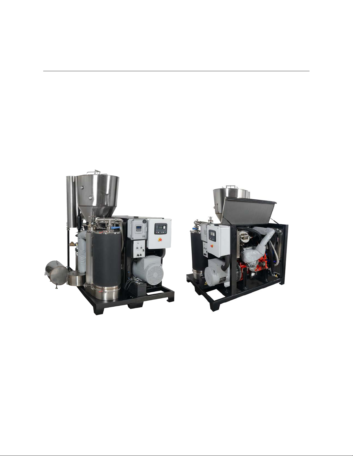
All Power Labs PP30 User manual

PP30 Operation Manual
PP30 Cogeneration System

Table of Contents
1. Technology Foundations 3
2. Power Pallet Crate Contents 6
3. Safety Procedures 7
4. Required Tools 8
O&M Tool List (Required) 8
Technician Tool List (Nice to Have) 9
5. Power Pallet Set Up 10
5.1. Facility Requirements 10
5.2. Connecting to Loads 12
5.3. Connecting to the Grid 12
6. Feedstock Requirements 13
7. Operating Procedures 16
7.1. PP30 Engine Pre-Start Duties 16
7.2. PP30 Gasifier Prestart Duties 22
7.3. PP30 Gasifier-Engine Startup 30
7.4. PP30 Shutdown 33
7.5. Refilling the PP30 36
8. Maintenance Schedule 37
9. Spare Parts 39
10. Service Record Form 40
2 of 41
FILE-004209 - Power Pallet Operation Manual (PP30)
1. Technology Foundations
Gasifier Supersystem (gasifier Module)
- The gasifier system
Power Generation Supersystem
- Power generation system
Combined Supersystem
- Power generation supersystem
- The gasifier supersystem
3 of 41
FILE-004209 - Power Pallet Operation Manual (PP30)

4 of 41
FILE-004209 - Power Pallet Operation Manual (PP30)

5 of 41
FILE-004209 - Power Pallet Operation Manual (PP30)

2. Power Pallet Crate Contents
1. Power Pallet Gasifier System
2. Power Pallet Generator System
3. Charcoal for first start of reactor
4. CO Monitor
5. Basic Tool Assortment
6. Set of Essential Spares
7. Miscellaneous supplies for maintenance operations
6 of 41
FILE-004209 - Power Pallet Operation Manual (PP30)
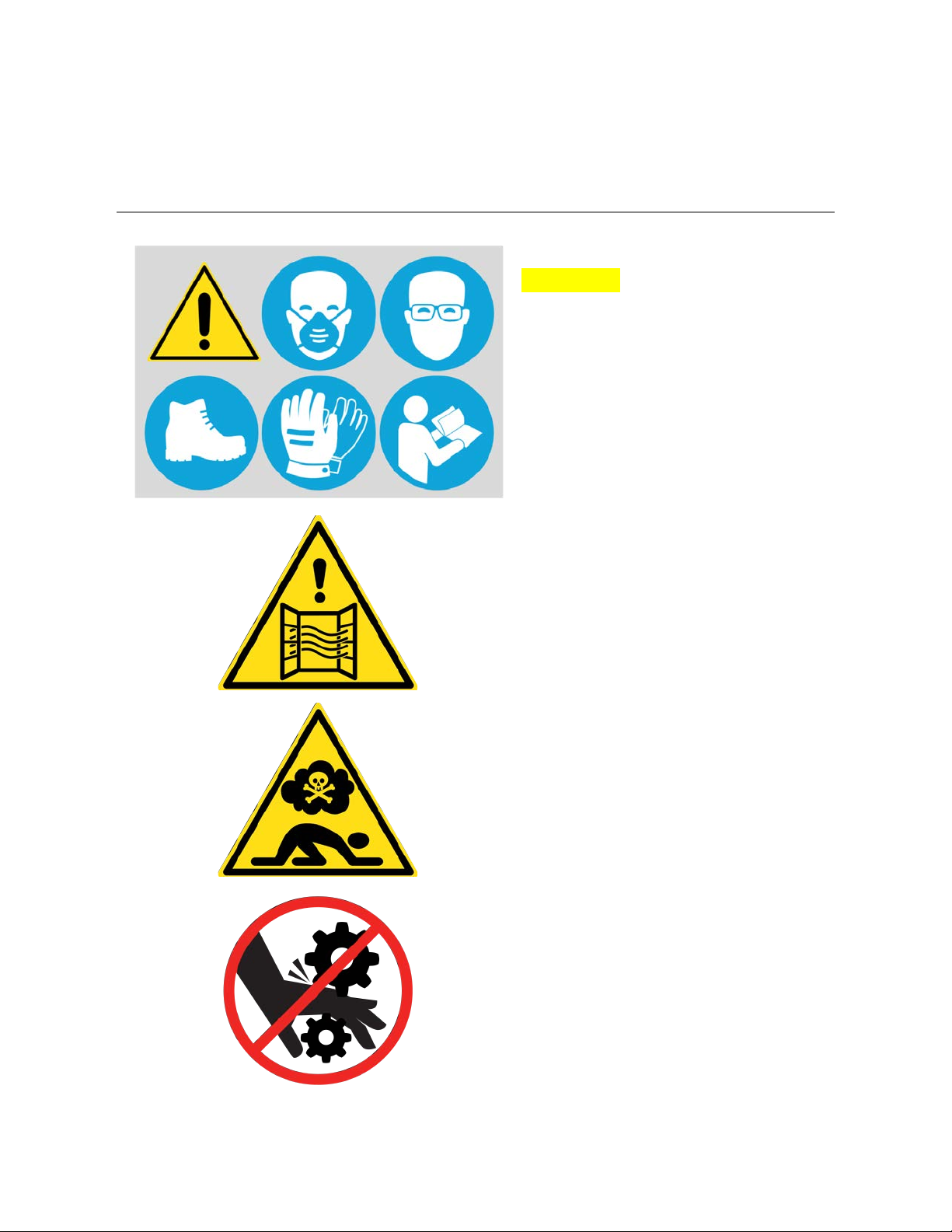
3. Safety Procedures
CAUTION: Operator must wear
personal protective equipment when
operating this machinery.
● Whenever filling or emptying
feedstock or char a mask appropriate to
protect against fine particulates must be
worn.
● Read all instructions and
documentation carefully before operating
or servicing.
● Service or operate only in a well
ventilated area.
● All vessels contain high
concentrations of toxic Carbon
Monoxide (CO) gas even when cool.
● Keep supplied CO alarm nearby
when operating or servicing.
● Do not service until machine has
been purged as described in section
7.3 of this manual.
● Do not service while machine is in
operation.
● Allow reactor to cool to room
temperature before servicing.
7 of 41
FILE-004209 - Power Pallet Operation Manual (PP30)

4. Required Tools
O&M Tool List (Required)
The following tools are required to perform regular Power Pallet O&M activities.
● Gas line wire brush
● 7mm wrenches
● 8mm wrenches
● ½” sockets and wrenches
● 9/16” sockets and wrenches
● 7/16” deep sockets
● ¾” wrenches
● ⅞” wrenches
● 9/64” Allen/hex wrench
● Allen/hex wrenches various sizes
● Crescent wrenches various sizes
● Phillips screwdriver various sizes
● Flathead screwdriver various sizes
● Scissors
● Sharpies or permanent marker alternative
● Blue paper tape
● Electrical tape
● Propane Torch
● Teflon pipe tape
● Denatured alcohol
● Paper towels
● Graphite paste
● ⅛” graphite rope
● ⅜” graphite rope
● Windows Computer
● Scale for measuring weight of fuel
● ½” pipe tee for lighting
● 12’ ladder
● 6x ~30 gal trash cans or equivalent for fuel loading
● 2x - 3x Carbon Monoxide Sensor
● ABC Fire extinguisher
● Water Hose
● Fork lift
● Big Wipes Heavy Duty Textured Scrubbing Wipes
8 of 41
FILE-004209 - Power Pallet Operation Manual (PP30)

Technician Tool List (Nice to Have)
The following tools will allow more complex Power Pallet O&M activities.
● Pliers
● Needle nose pliers
● Wire strippers
● Crimpers (ABCDE kind)
● Wire cutters
● Timing Light
● Voltmeter
● Cables/dongles for connecting computer to PP to load firmware
● Firmware
● Configuration tools
● DSE Software
● Tunerstudio Software for MS3 Pro
9 of 41
FILE-004209 - Power Pallet Operation Manual (PP30)

5. Power Pallet Set Up
5.1. Facility Requirements
The facility to house the power pallet must have the following characteristics:
● Level flooring made of non-flammable material capable of supporting the weight of the
machine (listed in the Specifications section).
● Facility must have a covered location to protect the power pallet from direct rain or water,
as some aspects of the system are not water/weather resistant.
● The system is to be installed with a 92 cm clearance around the footprint of the machine
and at least a 173 cm clearance above the machine. See illustration on the next page.
● Sufficient ventilation through an exhaust hood with air flow capacity adhering to local
regulations.
● Install the CO meter provided with the power pallet and verify that it functions properly.
Have a CO meter near the operating floor at all times even when the machine is not in
operation and especially when performing maintenance.
● Operate the power pallet in locations having a max temperature of 40 °C and at an
altitude of 1000m or less. The power pallet’s power output will be derated at higher
altitudes. In case of different conditions, please consult ALL Power Labs.
● Install the PP30 out of direct sunlight. UV from sunlight will damage parts over time.
10 of 41
FILE-004209 - Power Pallet Operation Manual (PP30)

11 of 41
FILE-004209 - Power Pallet Operation Manual (PP30)

5.2. Connecting to Loads
•Hook up the cam lock connections to an off load system you want to send
power to that is within the power pallet electricity load range. (5-25 kW)
• Press Close Generator button to close the contactor and start sending power to
an external load.
5.3. Connecting to the Grid
• Connect cam locks to interconnection point with grid.
• Press Close enerator button to close the contactor and start generator
synchronization process with the grid. If generator does not synchronize, please
look at technician manual for troubleshooting steps.
12 of 41
FILE-004209 - Power Pallet Operation Manual (PP30)

6. Feedstock Requirements
For your gasifier to operate properly, you must use the correct biomass feedstocks which have
been properly prepared and sifted. Certain material shapes and sizes flow better in solid
material handling systems. For example, long stringy pieces, similar to toothpicks, do not flow
well, as they get stuck in feeds. Materials in circular shapes such as walnut shells or macadamia
nut shells flow well.
Feedstock biomass must be dry, of the correct shape and size to flow through the reactor, and
free of dust, sand and contaminants:
●Particle size: 1 cm – 4 cm (0.5 in. – 1.5 in.)
●Moisture content (% by dry weight): 5% – 30%
●Ash content <5%
The following Table of Feedstocks shows the most common ones that have been tested and are
known to work, which ones are known to be unusable, and which ones need more testing. For
more information on fuel preparation, contact APL For more information on fuel preparation,
contact APL.
LEGEND
Green
Known to work with standard operations and maintenance
effort
Yellow
Known to work with increased operations and maintenance
effort
Grey
Not enough testing to approve at this time. Use voids warranty
Red
Known to not work. Use voids warranty.
13 of 41
FILE-004209 - Power Pallet Operation Manual (PP30)

Feedstock
Notes
Wood Chips (e.g: Oak, Rubber,
Pine)
Use only chips; chunks or long shards can bind au ger
or bridge in the reactor
Nut Shells (e.g: Coconut, Walnut,
Hazelnut)
Not all shells will work, please contact us to discuss
your particular feedstock
Corn Cobs
Must be broken to size and must not include husks.
Increased chance of slagging
Palm Kernel Shells
Risk of high temperatures. May need to be blended or
other steps taken to lower temperatures
Macadamia Nut Shells
Excellent shape, not enough testing
Cashew Nut Shells
Known toxicity, not enough testing
Wood Pellets
May work depending on size & makeup, pellets prone
to decompose
Coffee Grounds
Too fine for physical compatibility, pelletization may
allow use
Saw Dust
Too fine for physical compatibility, pelletization may
allow use
Corn stover
High ash content; silica content leads to slag
Rice Husk
High silica content leads to slagging
Bamboo
Difficult to prepare to correct size and shape
Grasses: Switchgrass, Miscanthus,
etc.
High silica and low bulk density.
Paper, Sugarcane Bagasse,
Coconut Husk
Shapes not physically compatible
14 of 41
FILE-004209 - Power Pallet Operation Manual (PP30)

Municipal Solid Waste/Trash
Slag risk; heavy metals; plastic content not suitable
Coal
Burns too hot, releases sulfur and heavy metals
Plastics
Melts and fouls auger/reactor
Manure: Cow, Pig, Chicken, etc
High slag, low energy density
Tires
Not chemically compatible
15 of 41
FILE-004209 - Power Pallet Operation Manual (PP30)

7. Operating Procedures
The following procedures assume that the Power Pallet has been assembled and installed
correctly. Training by a certified APL trainer is recommended before operating the PP30 for the
first time. For a list of all parts of the Power Pallet including a list of parts, definitions and all
other useful information see the PP30 Component Reference document.
7.1. PP30 Engine Pre-Start Duties
Power Generation Supersystem
1. Check DC battery voltage is over 12V (DSE->Engine->Battery Voltage)
a. Turn the the Power Pallet on by flipping the power switch up (Image 1)
Image 1
b. Starting from the Status screen press right arrow one time to get to the screen to
Engine screen (Image Set 2)
c. Then press down arrow 4 times to get to Engine Battery Voltage screen
d. If voltage is under 12V, connect and power on-board or external battery charger
16 of 41
FILE-004209 - Power Pallet Operation Manual (PP30)

Image Set 2
2. Check radiator coolant level and refill if needed (see PP30 Engine Check for fill instructions)
WARNING: Do not open the radiator cap when the unit is hot
Image Set 3
3. Check expansion tank fluid and refill if necessary (Image Set 4)
a. Fluid should reach the Normal line indicated in the picture
i. if it is below this line, fill up to the line
17 of 41
FILE-004209 - Power Pallet Operation Manual (PP30)
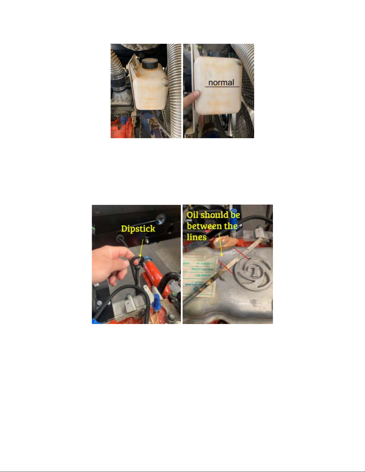
Image Set 4
4. Check engine oil level and refill if necessary (See PP30 Engine Check for fill instructions)
a. Pull the dipstick and clean it. Reinsert and pull it again and then check to see if
the oil is between the marking on the dipstick
b. If the oil level is low, add oil according to SOP
Image Set 5
5. Check Governor (Image Set 6)
a. Unplug the governor
b. Remove sanitary clamps and gaskets
18 of 41
FILE-004209 - Power Pallet Operation Manual (PP30)

Image Set 6
c. Physically check if the governor throttle plate moves freely (Image 7)
i. When pressed all the way open the throttle plate should close all the way
on its own with a snappy motion
Image 7
d. If check fails, clean governor (see PP30 Engine Check for cleaning instructions)
e. Re-install governor using sanitary gaskets and clamps and plug back in
19 of 41
FILE-004209 - Power Pallet Operation Manual (PP30)

i. Make sure to clean gaskets of tar and dirt before installation by wiping
them with a paper towel
ii. Ensure that the governor plug is facing downwards when you install it
Image Set 8
6. Check Polishing filter (Image 9)
a. Remove V-band clamp and sanitary clamp from lid and pull out the polishing filter
Pliers can help with the removal of the filter element
Image Set 9
b. Remove and inspect filter element (Image Set 10)
i. Inspection fails if the polishing filter
1. Appears dark black with no yellow on the far said
2. Is noticeably wet
20 of 41
FILE-004209 - Power Pallet Operation Manual (PP30)
Other manuals for PP30
3
Table of contents
Other All Power Labs Industrial Equipment manuals


