All Power Labs PowerPallet Manual

1
PowerPallet
Setup and Maintenance
Updated: 09/15/2012
ALL Power Labs, Inc
Berkeley, CA

2
Table of Contents
I. A Letter from ALL Power Labs
II. Recommended Tools
III. Setting up the PowerPallet
A. Fresh out of the ox- Final Assembly
a. Attaching Compnens
b. Wiring On-board System Components
c. Wiring the Generator
. Facilities
a. Feedstock Handling and Hopper Fill Options
C. Preparing the PowerPallet System
a. System Preparation
b. Pressure Testing
IV. Safety and Safety Features
A. Carbon Monoxide Safety
. Safety around Combustible Gases
C. System Safety
D. Environmental Precautions
V. Service and Maintenance of System Components
VI. Suggested Maintenance Schedule
A. Maintenance of PowePallet Components
a. Gaskets
b. Feedstock Hopper
c. Drying ucket
d. Feedstock Auger and Fuel Level Switch
e. GEK Gasifier Reactor
f. Cyclone
g. Gas Lines
h. lowers
i. Engine and Generator
ALL Power Labs, Inc
Berkeley, CA

3
I. A Letter from ALL Power Labs
Dear Customer,
Thank you for your support Your PowerPallet is a stand-alone, fully integrated power station
including the GEK Gasifier, engine, and generator for power generation from biomass. The
maintenance schedule for the PowerPallet system we recommend is on a more conservative schedule.
We highly recommend checking the following items frequently when using a new type of feedstock of
feedstock characteristics for the first time.
The composition of biomass feedstocks are naturally variable in their characteristics and because the
fuel is a solid, it is inherently more difficult than the convenient and consistent liquid fossil fuels to
which the world has become so accustomed.
Like other biomass energy services (ie: wood stoves, boilers, gasifiers, etc.) hands-on maintenance
considerations will be needed (ie: ash/char purging, flue cleaning, condensate traps, cleaning of build-
up, etc) to maintain the efficiency of the system.
All downdraft gasifiers (and most all gasifier designs for that matter) are sensitive to variations from
‘ideal’ feed stocks. Because we are unable to test all types of biomass feed stocks around the world, we
encourage you to take an active and observant role into the maintenance tasks and schedule for the
first of several run cycles. This will ensure the system as a whole runs in a safe manner at its highest
efficiency, with the lowest possible emissions, and have a longer total life overall. We highly
recommend keeping a maintenance and operation log of the feedstock characteristics used, time of
start- up, notes on temperature and pressure, full run time, generator load, maintenance tasks done
and notes. As you run the system over many cycles, you will discover the feedstock’s degree of
deviation from ideality and will be able to adjust the maintenance schedule from what is conservatively
suggested below.
Information from you in the field is very important to us as we make system developments and offer
upgrades to current customers like yourself. We would greatly appreciate these notes from you as we
are constantly improving our system design and documentation based on reports from people like you.
If damages occur, we will request your maintenance log to determine the discount for replacement
parts.
Please take part in helping us create and improve low cost renewable energy solutions for changing
world by contributing your run notes, suggestions, comments, and pictures. We greatly appreciate your
support and if you need anything please contact us.
Thank you,
ALL Power Labs
R&D, Technical Support and Customer Relations Teams
ALL Power Labs, Inc
Berkeley, CA

4
II. Recommended Tools and Materials
•2 x 1/2 wrench or ratchet
•adjustable wrench
•Phillips and flat head screwdriver
•broom handle or long rod
•pipe wrench
•silicone RTV (provided)
•high temp mortar (provided)
•caulking gun
•teflon tape (provided)
•step stool
•box knife and scissors
•Engine oil
•Engine coolant
•12v DC car battery
•car battery charger (if needed)
•hex wrench (size)
•bucket
•voltmeter
•small 12v air compressor or air pump
•fine sifting screen and 1/2 sifting screen (filter media)
•1/2'' and 1'' sifting screen for feedstock (if needed)
•large bottle brush
•pallet jack or forklift
•shop rag
•isopropyl alcohol
•soapy water
ALL Power Labs, Inc
Berkeley, CA

5
III. Setting-up the PowerPallet
A. Fresh out of the ox- Final Assembly
We pressure test and run each PowerPallet before shipping to make sure it meets quality
standards. After testing the system is prepared for shipping. efore starting your new PowerPallet,
minor assembly and system preparation is needed.
a. Attaching Components
ecause of the variability in packing, this list may include components that are already
assembled onto the main unit. Some of these items may have shipped in boxes or may be
located in the Gas Filter arrel.
Feedstock Hopper Barrel
The Hopper arrel is detached for shipping. Attach the Hopper arrel to the Drying
ucket by screwing the 5/16ths bolts provided into the threads of the Hopper arrel.
Make sure the seal is gas tight.
Flare Stack
Attach the Flare Stack to the top of the Pyrocoil lid.
Blowers
•Connect the two Gas lowers in series and attach them to the longer inlet of the Flare
Stack. The Gas Line will connect from the bottom of the Gas Filter to the inlet of the
Gas lowers.
•For the single Air lower, attach the flange to the shorter inlet of the Flare Stack. Make
sure the orange silicone check gasket is seated properly in the guard at the inlet.
Igniter
The igniter will attach to the top of the flare stack.
Exhaust
Connect the Muffler Stack to the square flange on the Pyrocoil using the crush gasket.
Condensate Traps
Attach the Cyclone Condensate Jar to the Cyclone, use the silicone RTV to seal the
threaded jar connection to ensure a gas seal. Attach the Engine Condensate Jar to the T-
fitting in the Gas Line leading to the engine.
Grate Shaker
Thread the end of the Grate Shaker Shaft into the nut of the Ash Grate, make sure the
connection is secure. olt the Grate Shake assembly onto the Grate Shake Port on the
Gas Cowling. Tighten the shaft collar using a hex wrench.
b. Wiring On-board Components
Grate Shaker
Connect the red and black wires on the grate shaker to the orange and black wires from
the wiring harness. The two other wires (orange and yellow) on the grate shaker will
remain disconnected.
ALL Power Labs, Inc
Berkeley, CA
6
Flare Igniter
Connect the two wires on the ignitor to the two wires with the mating connections at the
top of the wiring harness channel. The igniter wires are not polarized.
Blowers
The three blowers will each need to be connected to the mating connectors in the wiring
harness. Match the number of dots on the connectors when connecting the mate.
Battery
Unfortunately we are not able to ship a battery with the PowerPallet. Obtain any size12V
DC car battery and connect it to the positive (red) and negative (black) leads provided on
the PowerPallet.
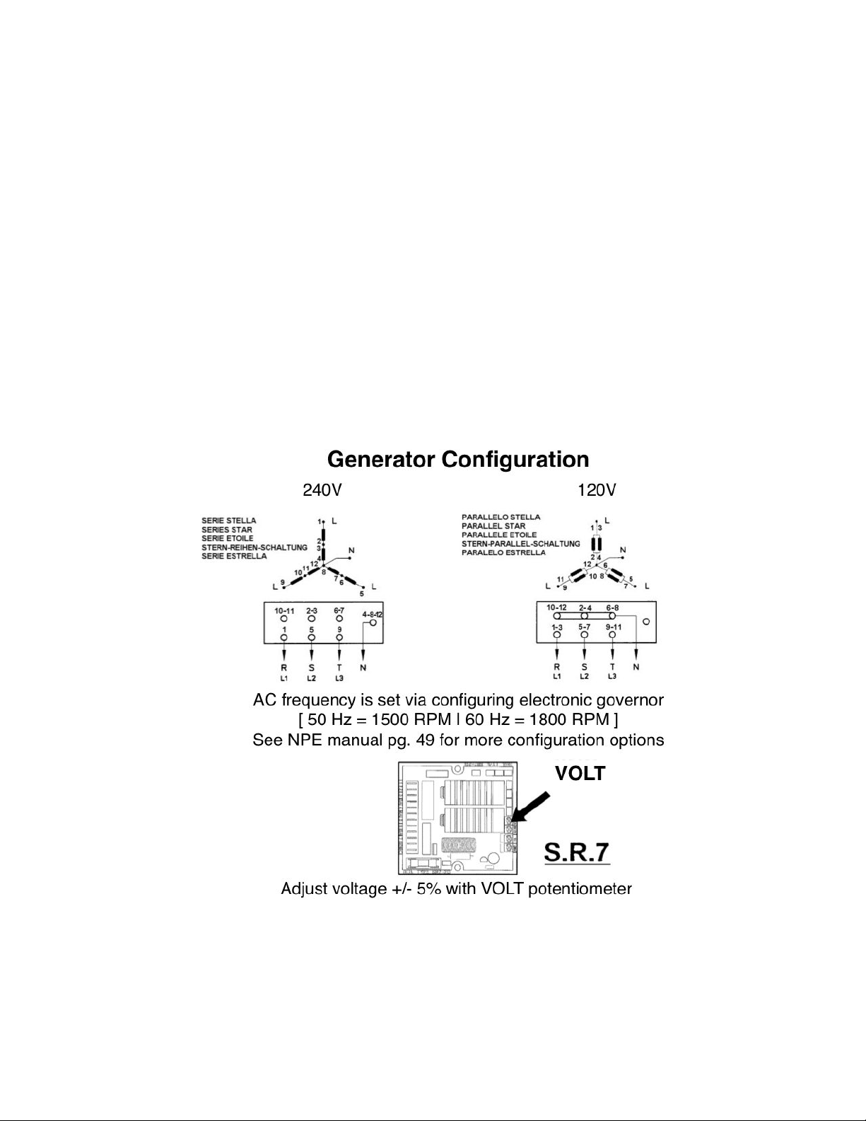
c. Wiring the Generator
If you specified the voltage and frequency at the time of order, the unit may have been
configured to you specifications before shipment. To wire the generator to your specifications,
unscrew the cover lid off of the generator and use the guide diagram below.
The series star or parallel star configuration are shown above for 240V and 120V
configurations. In the box, leg 1, 2 and 3 (L1, L2 and L3) and neutral (N) are shown. Match the
wire numbers 1 - 12 in the diagram above with the terminal as printed on the wire housing in
ALL Power Labs, Inc
Berkeley, CA

7
the generator. For finer adjustments of the voltage, use the volt potentiometer shown in the
diagram above. For sensitive electrical equipment, it is recommended to use a universal power
supply (UPS) or universal power converter (UPC).
For more information please read the Meccalte Generator Manual provided on the US drive
included with the PowerPallet.
. Facilities
The PowerPallet can be moved simply with a pallet jack or a forklift. Mobilizing additions, such
as locking caster wheels, could be installed if desired. When choosing a location to set up and run the
PowerPallet, please make the following considerations as to the facility:
•The area around and above the PowerPallet should be well ventilated during operation.
•ecause it is possible that the flare may rise above the flare stack during normal operation,
above the opening of the flare stack should be unobstructed and clear of any objects. If needed,
a hooded flue could be used to pass the flue gasses through a roof, however an opening
•(or after burner) should remain at the top of the flare stack.
•The bottom of the flare stack will become very hot. Make sure that enough space is available
around the flare.
•For operation and maintenance, it is ideal to have enough room to walk all the way around the
Powerpallet.
•The location should be covered from rain.
•The PowerPallet should be on a flat surface.
•An area 5 feet surrounding the PowerPallet should be free of leaves or combustible materials.
•Well ventilated area is needed during maintenance! CO exposure is very rare during operation,
however, caution is needed when opening the system up for maintenance- system should always
be purged first before opening.
•The noise level is about 60db (10kWPP) and 70d (20kWPP) @7 meters. This is much quieter
than small cheep generators, and similar to standing outside a car with the hood down.
eedstock Handling and Hopper ill Options
The hopper that is sent with the PowerPallet and the GEK Kits is optimized for shipping a
compact system to locations all around the world. The feedstock hopper barrel is to be filled from the
top. This can either be done by hand using a step stool, from a top level or front loader. From here the
feedstock is able to flow through the gasifier system. While we can offer this to you anywhere in the
world at low cost, some have adapted the hopper and loading to fit their specific end use and facility.
Alternative hopper and upstream feeding systems may be adapted to the Drying ucket flange.
The requirement for the GEK System is to be air tight including the hopper. However, periodic filling
of the hopper during operation is possible, however do not compromise the hopper seal for more than 8
seconds (10 max). Adaption of an air lock and vertical auger for feedstock transport and feeding is
possible for the PowerPallet and GEK Kits if desired.
ALL Power Labs, Inc
Berkeley, CA

8
C. Preparing the PowerPallet System
a. System Preparation
GEK Reactor
Fill the GEK Reactor with real wood charcoal between 1/2 - 1.5'' particle size. Make
sure that the charcoal completely fills the entire space between the ash grate and ~6''
from the top of the lid. (Note: this will only have to be done the first time since charcoal
is produced in the process of running. It may be easier to fill the reactor with charcoal
before placing the Hopper onto the Drying ucket. Fill the Drying ucket with charcoal
and turn the system power on to initiate the auger feed. Use a long pole to assist the
charcoal toward the bottom of the reactor to completely fill the space below)
Gas Filter
Filter media will need to be added to the gas filter. The gas filter comes with two grates
and two filter foam disks. To prepare the two filter foam disks, they are to be dipped in a
clean oil with the excess squeezed out. From bottom to top, layer the filter as follows:
filter grate rests on the bolts at the bottom of the filter
charcoal filter media between ~1/16 - 1/2'' particle size filled to ~10'' from the
top of the filter.
prepared foam filter disk 65dpi (larger pore size)
prepared foam filter disk 45dpi (smaller pore size)
second filter grate
The media should fill the grate just so the foam filters are almost touching the lid of the
filter, but are not compressed when attaching the filter lid.
Feedstock Hopper
Fill the hopper up with the recommended feedstock. Never run the system with a
completely empty hopper. For more information on feedstock requirements, please read
the iomass Feedstock Requirements documentation.
Engine
Add coolant and oil to the engine according to the engine manufacturers specifications
outlined in the Engine Manuals included in the documentation for the PowerPallet.
b. Pressure Testing
Pressure testing should always be done to ensure that no air will leak into the system during
operation, or that CO can not leak out of the system when shut down. There are a few ways to pressure
test for leaks, two methods are suggested below.
•Pressurize the system to 1-2psi, use soapy water to test joints.
•Create a small amount of smoke inside the reactor and pressurize the system to 1-2 psi.
Look for leaking smoke.
ALL Power Labs, Inc
Berkeley, CA

9
IV. Safety and Safety eatures
A) Carbon Monoxide Safety
Stay out of gasifier gas at all times.
Gasifiers intentionally generate carbon monoxide and other volatile organic gases as an interim
step before combustion of the gas in a flare or engine. While these gasses are produced in a closed
system under vacuum on-demand, use caution in using the equipment correctly so as not to be exposed
these harmful gasses. Always use a gasifier outdoors, and with extensive ventilation. Always stay out
of the smoke and/or produced gas before it is combusted. This is NOT typical campfire smoke, even
though it may smell similar. The carbon monoxide concentrations in gasifier gas are higher than in
other "smokes". If you do not stay out of the smoke, you can get in trouble quickly, usually before you
realize it, please be aware.
Even though the gasifier system may be turned off, the gasses will still be inside the system.
Please take note that when you are doing maintenance (especially opening the hopper or the gas
filter) that the system still contains large amounts of producer gas.
Always have a carbon monoxide meter in the area where you are working. Carbon monoxide
meters are included with the GEK Gasifier Kit and are also available at hardware stores in the
smoke detector section. Review the health guidelines of carbon monoxide:
http://www.osha.gov/SLTC/healthguidelines/carbonmonoxide/
) Safety with Combustible Gases
Please pressure test the system before operation if a leak is suspected.
While we do perform pressure tests on the system to detect for leaks before all of our
shipments, seals may become compromised during shipping or over many hours of running. ecause
the system operates under a vacuum, gaps in the system will allow air to leak into the system (instead
of producer gas/CO leaking out of the system). If enough air is allowed into into the system (typically a
larger leak instead of a very tiny pinhole), there is a potential for stoichiometric mixtures of
air/producer gas to occur inside the system. This leaves a potential for a lighting event to occur inside
the system causing a quick pressure expansion event. The pressure release valves are intended to
release this pressure safely if this does occur.
Do not operate the GEK Gasifier Kit or PowerPallet with an empty hopper or gas filter.
If the reactor becomes empty of feedstock, the air allowed into the gasifier will no longer be
consumed in combustion. Air into the system that includes the hopper volume of wood gas has the
potential to rapidly expand. While a release valve is located on the hopper, this can potentially damage
the hopper lid. An alarm will sound and the LCD screen will display a warning when the auger detects
that the system is close to running out of feedstock.
On start up, air may be in the system, but will be purged out in time before combustible gases are
formed. However, an empty gas filter has the potential to contain a large volume air and gas mixture in
the system. Please never run without filter media in the gas filter.
C) System Safety
Caution, hot surfaces.
The gas cowling of the GEK Gasifier tends to get very hot during operation. The flare stack also
ALL Power Labs, Inc
Berkeley, CA

10
gets hot when running. During normal operation, the flare may be seen at the top of the flare stack.
While rare, very small pieces of charcoal that may entrain in the gas stream may pass through the flare.
Also, if the system is on, the igniter for the flare at the top of the flare stack may turn on.
Caution, rotating parts
While working around the system filling with feedstock or charcoal, or using tools around the
system, make sure nothing falls in the way of the rotating components of the generator or engine.
System not to exceed vacuum limits
The system runs under a slight vacuum while allowing air to enter into the air inlet on the GEK
Gasifier for gasification. Always keep the air inlet open while the system is running, especially the
engine, to prevent further increasing the vacuum past the system limits.
D) Environmental Precautions
Periodically, the condensate traps of the cyclone, gas filter and engine gas line need to be
emptied. While the high efficiency of the GEK Gasifier produces very little wood tar, the amount that is
produced will need to be disposed of in an environmentally responsible way. It is not advisable to pour
wood tar on the ground. Remaining within the feedstock requirements and the use of drier feedstocks
will allow the system to run at its max efficiency and will reduce the amount of tar produced. Any tar
that is produced can be disposed of responsibly with waste oil. The spent filter media is to be dried and
added back into the feedstock at no more than 10%.
ALL Power Labs, Inc
Berkeley, CA

11
V. Service and Maintenance of System Components
ALL Power Labs offers extra and replacement parts at our costs for servicing your system.
While we provide this as a service to you, our support team will also help you source replacement
parts, if needed, locally or through online providers. Also offered is the Research Experimenters Kit
that includes equipment for controlling gas flow, testing gas quality, monitoring reactor conditions, and
more.
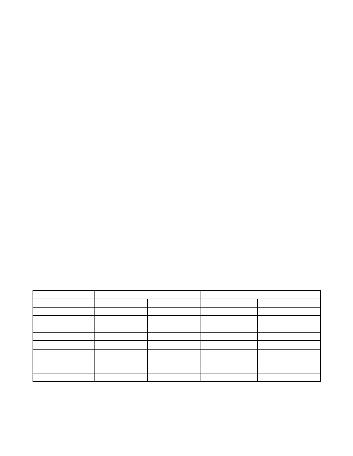
A. Suggested Maintenance Schedule
Item efore
each run
10-12
hrs
50hrs/
10cycles
300hr/
50cycles
1000hrs/
100 cycles
GEK
Inspect Gaskets X
Purge Char from Reactor X
Check/Clean Cyclone X
Check/Empty Cyclone Condensate Jar X
Check/Change Gas Filter bulk media X
Check/Clean Gas Filter Foam Disks X
Check/Clean Gas Lines X
Check/Clean Dual Gas lowers X
Check Reactor Air Lines X
Check Reactor Reduction ell X
Check Reactor nozzles X
Engine
Check/Purge Air Filter X
Engine Condensate Jar X
Check Spark plugs X
Engine oil X
Throttle valve X
Recalibrate O2 Sensor X
Please also refer to the engine and generator manufacturer's maintenance schedule included in the
engine and generator operation manuals
ALL Power Labs, Inc
Berkeley, CA

12
VI. Maintenance of PowerPallet Components
For maintaining the components of the GEK Gasifier system components, some disassembly may be
required. For assembly instructions for the GEK Gasifier, please refer the GEK Gasifier Kit Assembly
Instructions.
WARNING: When doing any maintenance or opening of the PowerPallet or GEK Gasifier systems,
do this in a well-ventilated area using the CO meter provided. The closed system will contain CO
from the previous run. It is highly suggested to turn the Gas lowers on high for up to 1- 2 minutes
with all valves open to purge the CO out of the flare stack before doing maintenance on the system.
Gaskets
Gaskets will wear over time depending on frequency of separation and attachment of
neighboring flanges or components. To ensure a longer life, be careful not to damage, pinch, stretch, or
over-tighten components. The silicone gaskets are considered over-tightened if they bulge from the
flange mate. Typically the most frequently worn due to activity and system maintenance may be the
reactor lid port cover silicone gasket, hopper lid gasket, gas filter gasket and the cyclone condensate jar
gasket. Make sure it is able to maintain a gas tight seal. If needed, re-apply the gasket material and use
the high temp mortar or the silicone RTV.
Feedstock Hopper
As the hopper lid may be used often, make sure this hopper lid maintains a good seal.
Drying ucket
The Drying ucket baffles help increase the heat exchanging capacity as well as knocking small
particulates out of the gas stream. Over time, build up may occur. To clean, unbolt the bottom flange
and use a large bottle brush to break any build up free.
Feedstock Auger and Fuel Level Switch
The auger is intentionally angled slightly downward to prevent the auger from jamming by
riding upward on top of the feedstock. If large or difficult feedstocks are used, there is a potential to
bend the auger. If this happens, unbolt the auger motor flange, slide the auger out and bend it back into
place.
The current of the auger is detected by the PCU. Depending on your feedstock characteristics,
the difference between the max and min current monitored by the PCU logic may need to be adjusted.
The factory settings usesd are for wood chips between 0.5 and 1.5'' particle size. The auger settings are
user configurable. Refer to the KS_PowerPallet v1.1Controls documentation for more information.
GEK Gasifier Reactor
•Air Lines
Take the Reactor Vessel out of the Gas Cowling and use a wire brush to remove any build up
around the air lines. Check to make sure the air lines have not been cracked or have
experienced other damages.
ALL Power Labs, Inc
Berkeley, CA

13
•Gas Cowling
While inspecting the air lines, use the wire brush to clean any build up along the vessel
walls, and the gas exit port through to the cyclone.
•Cleaning out Char/Ash from Reactor
The Grate Shaker purges the smaller char/ash particles to maintain proper gas flow
throughout the reaction chamber. Purge the ash/char from underneath the grate by opening the
ash port on the gasifier. The char/ash can be cleaned out with a long rod or a vacuum cleaner.
e aware that if the charcoal is hot, air allowed into the gasifier may start to light the charcoal.
This high temp char is perfect as the final stage filter media for the Gas Filter. e sure to
sift out the fine dust, see Filter Media.
•Reduction ell
Due to high thermal cycling over long run times at high temperatures in a harsh
combustion and a reduction environment, over time the Reduction ell will need to be checked
for any accumulated damage that may have occurred. If the reactor is run at temperatures over
the maximum operation temperatures, damage to the reduction bell at the restriction or the
bottom of the reduction bell could occur.
Make sure that the reduction bell bolts are securely in place. After many thermal cycles,
these bolts may become lose. If they are lose, use the high temp mortar to screw them back into
place. Loose bolts can allow local combustion to occur and may burn through the air lines at the
bottom of the reactor.
•Air Nozzles
ecause the highest temperatures are experienced at the tip of the air nozzles of any
gasifier system, these will need to be checked for any thermal damage. Check the tip of the
Nozzles to make sure the opening has not enlarged due to melting or corrosion.
•Cyclone
It is possible for soot and particulates to stick and build-up in the gas lines and cyclone
over time. To maintain the efficiency of the cyclone, detach the cyclone condensate jar and use
a large bottle brush to purge any particulate build up.
•Cyclone Condensate Jar
The cyclone jar should be emptied if full. Un-thread the jar and empty. When reattaching
the condensate jar, be sure to create a gas tight seal Apply the silicone RTV provided, if needed.
•Gas Filter
The saw dust or char media used for the bulk of the gas filter media traps any soot, tars,
and condensate in the gas stream before entering the engine. Check the condensate level of the
Gas Filter by looking at the level viewing port at the bottom of the gas filter The LCD screen
may indicate "bad filter" if the difference between the reactor pressure (P_react) and the filter
pressure (P_filt) is greater than 3WC.
If the filter media needs changing, disconnect the bottom inlet gas line, open the lid, and
remove the gas filter from the pallet to empty. Use a wire brush to scrape the grates and the
walls of the filter clean of soot/particulate build-up. The spent filter media can be dried and
added back into the feedstock at ~10%.
The foam filter disks can be cleaned with warm soapy water. Dry the foam filter disks
ALL Power Labs, Inc
Berkeley, CA
14
and soak them in clean oil and squeeze out the excess. Make sure the filter foam disks
completely touch around the inside wall of the gas filter housing so that gas can not pass around
the edges.
Gas Lines
Open the gas line clean out port near the connection at the bottom of the gas filter. Use this port
to empty any condensate and use a large bottle brush to clean out any build-up inside the gas line.
lowers
Gas lowers may need to be checked for build-up on the fan blades. If build-up does occur,
disassemble the fan and clean blades and housing with isopropyl alcohol.
Engine and Generator
•Air Filter
Check to make sure the engine’s air filter is not clogged.
•Engine Condensate Jar
Empty any condensate collected in the jar before each run. There may be an oil layer in
the condensate jar if any oils happen to carry over from the foam filter disks.
•Throttle Valve
Make sure the throttle valve is free of any build up that may have occurred over time. If
build-up does occur, (ie: wood tar, or oxidation) clean with isopropyl alcohol.
•Intake Valves
If tar is allowed into the engine, build up may occur on the intake valves. The first
indication of this is if the valves start to stick thus making it difficult for the engine to start. If
this is suspected, remove the valves. Clean with isopropyl alcohol if needed.
•Spark Plugs
As a precaution, check to make sure the spark plugs are free of any build up. If the spark
plugs are replaced, adjust the spark gap to our specs to prevent backfiring.
Engine and Generator Specifications
20kWPP 10kWPP
Frequency (Hz) 50 60 50 60
Engine GM Vortec 3000 GM Vortec 3000 Kubota DG-972 Kubota DG-972
Generator Meccalte NPE32 Meccalte NPE32 Meccalte ECP3_2 Meccalte ECO3N_4
RPM 1500 1800 3000 1800
Generator Poles 4 4 2 4
Spark Advance ~7.5° from stock ~7.5° from stock 10° from stock Stock
Max iomass
Consumption
(kg/hr)
26.8 26.8 13.4 13.4
Db rating @7m 70 70 60 60
For more information about the engine and generator, please see the associated manufacturer manual.
ALL Power Labs, Inc
Berkeley, CA
Table of contents
Other All Power Labs Industrial Equipment manuals


