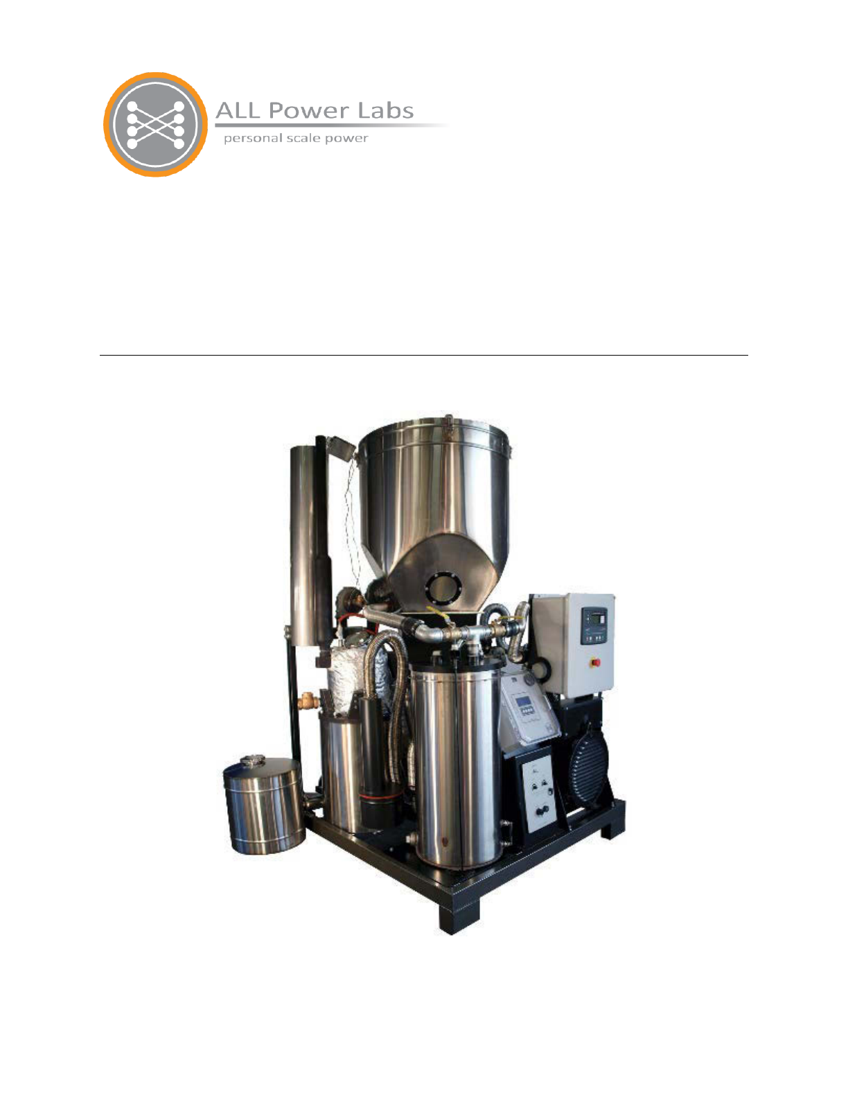
All Power Labs Power Pallet PP20 User manual

1010 Murray Street Berkeley, CA 94710, Tel. 510-845-1500 Toll Free 888-252-5324
support@allpowerlabs.com www.allpowerlabs.com
Section 1 - Introduction to the Power Pallet
Section 1
Introduction to the Power Pallet
PP20 v1.08, v1.09
(PP20-GT 1.09 displayed)
Page 1-1
770-00084 Section 1_Introduction to the Power Pallet (PP20) Rev B
770-00083 Power Pallet Technician's Handbook (PP20/v1.09) Rev B

Section 1 - Introduction to the Power Pallet
Table of Contents
1. Overview
1.1 Conceptual overview
1.2 Sequence of Processes
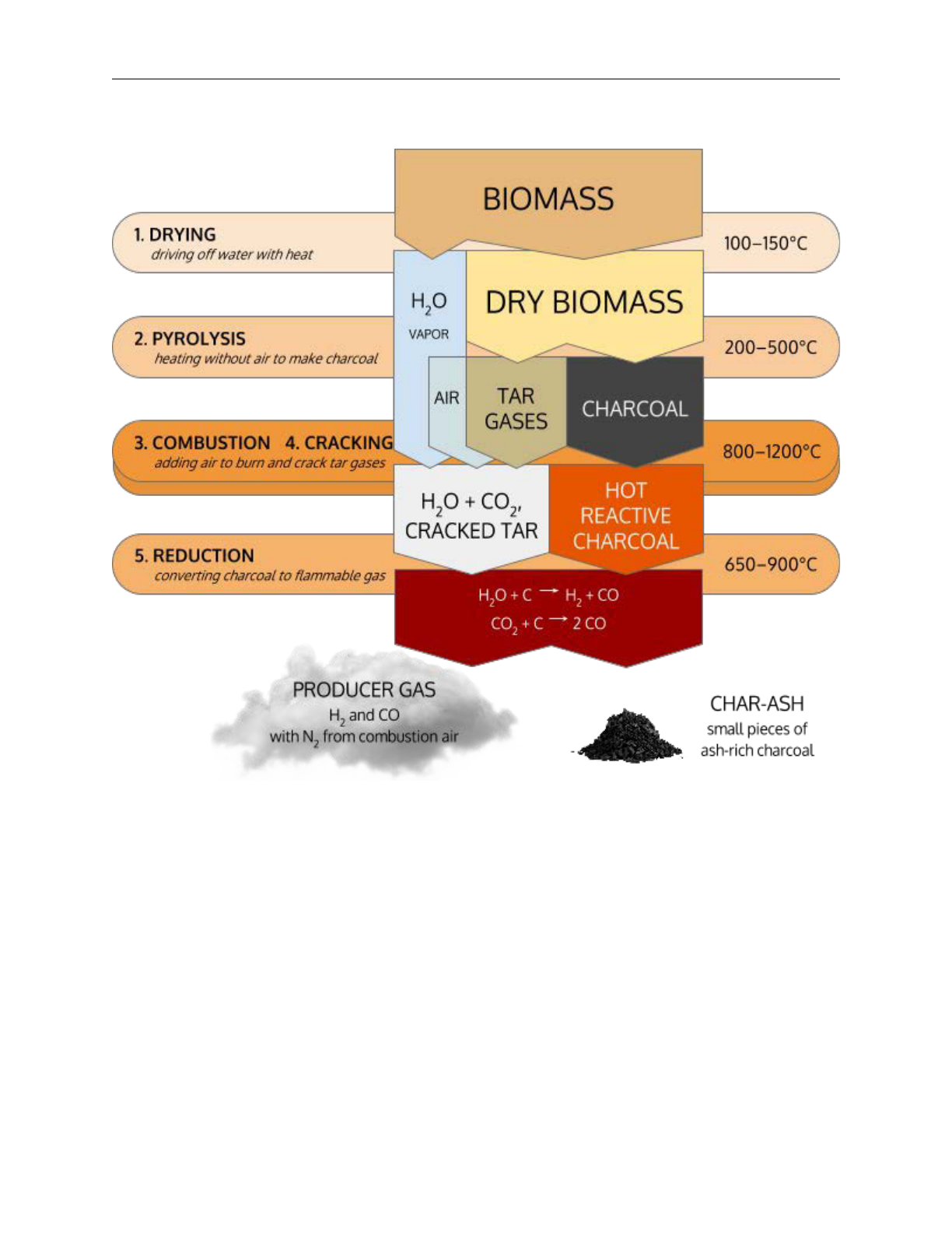
Graphic A: The Five Processes of Gasification
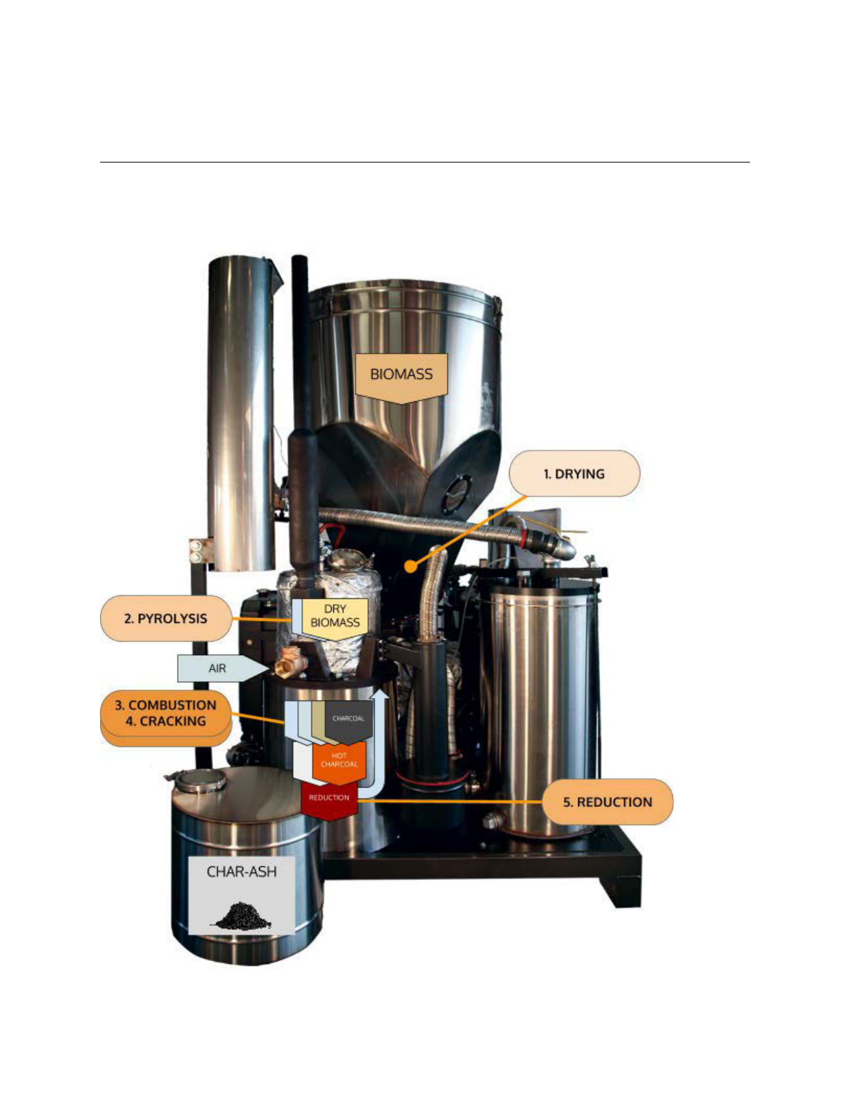
Graphic B: The Five Processes and the GEK TOTTI
Graphic C: The Five Processes and the GEK TOTTI–photo overlay
2. Flow of Solids
2.1 Drying
2.2 Pyrolysis
2.3 Combustion and tar cracking
2.4 Reduction
2.5 Purging char ash
3. Flow of Gases
3.1 First stage of waste heat recovery: Preheating intake air
3.2 Removing particulates: Cyclonic dust separation
3.3 Second stage of waste heat recovery: Drying the feedstock
3.4 Gas filtration
Note: gas temperature at the base of the filter
3.5 Air mixing
3.6 Combustion of producer gas in the engine
3.6.1 Engine output regulated by the MPU
3.6.2 Note: unique combustion characteristics of producer gas
4. Flow of Exhaust
4.1 Third stage of waste heat recovery: Exhaust-heat assisted pyrolysis
5. Automation
6. Identifying Power Pallet components
Exhibit A: Front view
Exhibit B: reactor side view
Exhibit C: Engine corner view
Exhibit D: Detailed Views
Exhibit E: PCU and control panel
Page 1-3
770-00084 Section 1_Introduction to the Power Pallet (PP20) Rev B
770-00083 Power Pallet Technician's Handbook (PP20/v1.09) Rev B
Section 1 - Introduction to the Power Pallet
1. Overview
1.1 Conceptual overview
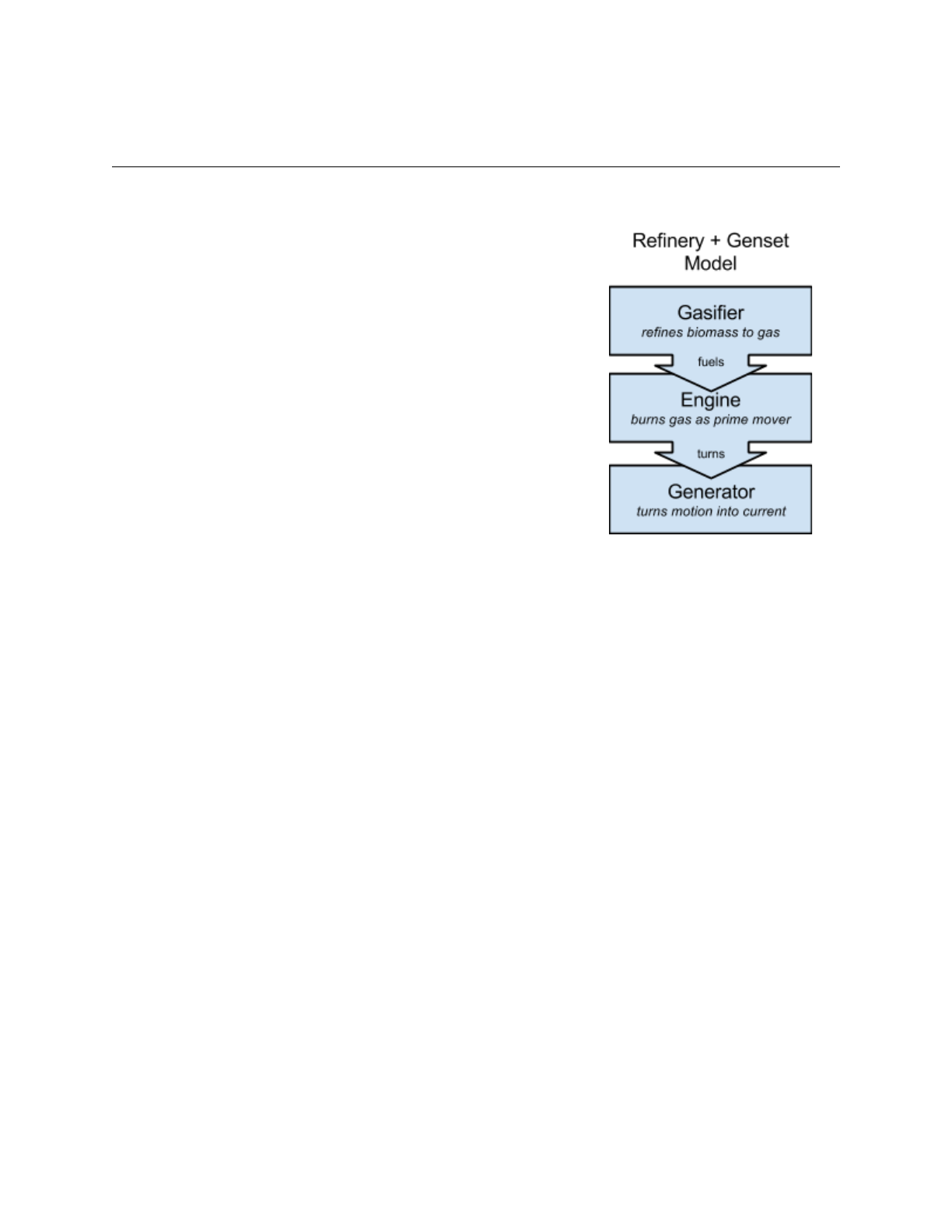
The Power Pallet system is comprised of the GEK TOTTI
series gasifier integrated with automation system and an
engine coupled to a generator. The purpose of the gasifier is
to refine biomass feedstocks into a clean-burning gaseous
fuel (producer gas) that is compatible with internal
combustion engines. The gasifier converts cellulosic biomass
feedstock into producer gas using the processes of
gasification. Producer gas is made up of about 20% H2 and
20% CO, which are both gaseous fuels that the internal
combustion engine burns to generate power.
1.2 Sequence of Processes
The major processes of gasification are as follows:
●Drying — removal of moisture from the feedstock
●Pyrolysis — thermal breakdown the feedstock into tar gases and charcoal
●Combustion and tar cracking — burning of charcoal and tar gases to provide heat for
the rest of the processes and the thermal cracking of a portion of the tar gases into CO
and H2 gas.
●Reduction — reaction of combustion products and charcoal to produce gaseous fuel.
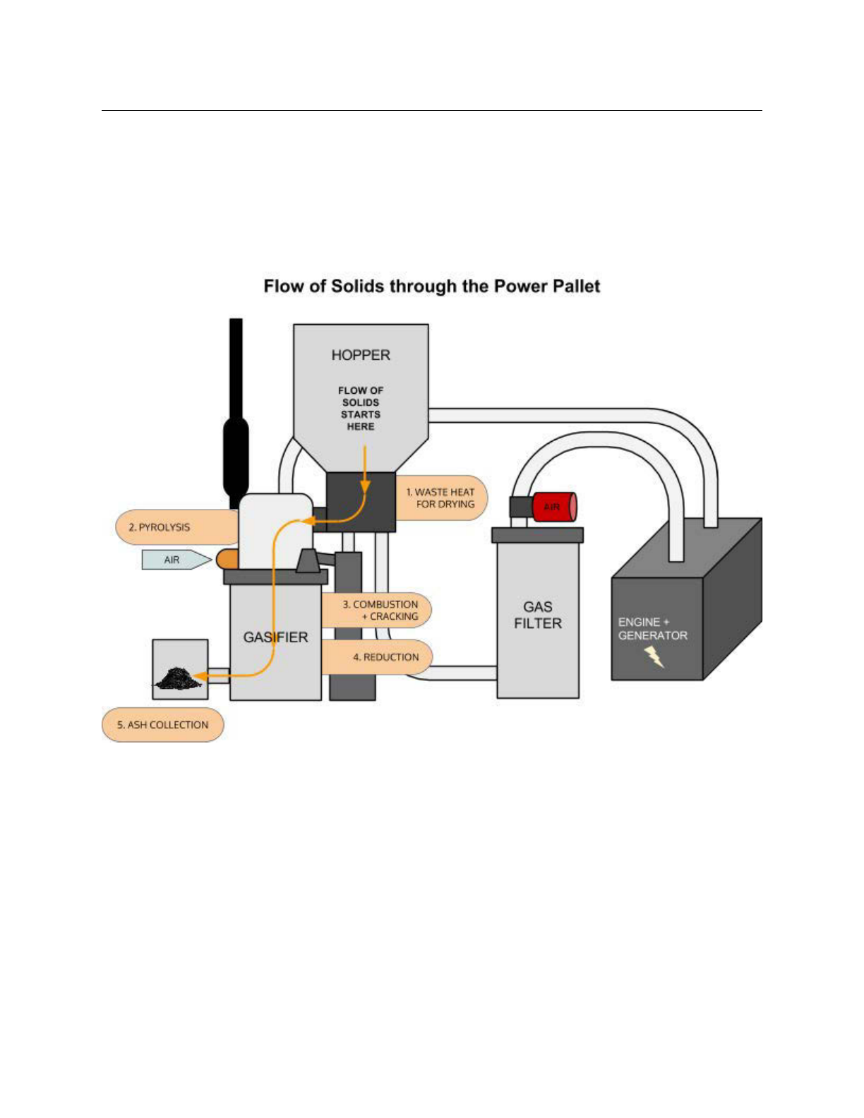
In the process of producing electricity, there is a sequence of flows from the hopper to the
exhaust pipe:
1. the flow of solids —
Biomass feedstock starts in the hopper, flows through the drying bucket and the
PyroReactor, and ends in the ash collection vessel.
2. the flow of gases —
Gaseous fuel is produced towards the bottom of the reactor, flows through two heat-
recovery stages, and is consumed in the engine.
3. the flow of exhaust —
The engine exhaust is directed through a heat-recovery stage before being released to
the atmosphere.
Extensive recovery of waste heat is one of the features that sets the Power Pallet apart,
resulting in cleaner gas output as well as higher efficiency.
Graphic A: The Five Processes of Gasification
Page 1-4
770-00084 Section 1_Introduction to the Power Pallet (PP20) Rev B
770-00083 Power Pallet Technician's Handbook (PP20/v1.09) Rev B
Section 1 - Introduction to the Power Pallet
The processes of gasification converts biomass into a clean burning gas which can fuel an
internal combustion engine. Gasification involves subjecting biomass to the processes of drying,
pyrolysis, combustion, cracking, and reduction. Tar cracking breaks down tar gases into carbon
monoxide, hydrogen, and other light gases by exposure to high temperatures, and reduction
converts charcoal into carbon monoxide and hydrogen by percolating the carbon dioxide and
water vapor produced during combustion through hot charcoal. The resulting combustible
mixture of combustible gases and atmospheric nitrogen is known as producer gas.
Page 1-5
770-00084 Section 1_Introduction to the Power Pallet (PP20) Rev B
770-00083 Power Pallet Technician's Handbook (PP20/v1.09) Rev B

Section 1 - Introduction to the Power Pallet
Graphic B: The Five Processes and the GEK TOTTI
Schematic of the GEK TOTTI gasifier system
Page 1-6
770-00084 Section 1_Introduction to the Power Pallet (PP20) Rev B
770-00083 Power Pallet Technician's Handbook (PP20/v1.09) Rev B
Section 1 - Introduction to the Power Pallet
Graphic C:
The Five Processes and the GEK TOTTI–photo overlay
Overlay of the processes on a photo of the GEK TOTTI system
Page 1-7
770-00084 Section 1_Introduction to the Power Pallet (PP20) Rev B
770-00083 Power Pallet Technician's Handbook (PP20/v1.09) Rev B
Section 1 - Introduction to the Power Pallet
2. Flow of Solids
Within the gasifier the solids flow downward by gravity, while the gases are pulled through the
system by the vacuum produced by either the engine or the gas blowers of the flare system
during start-up. The following section describes the major processes of gasification to produce
producer gas from biomass feedstock.
2.1 Drying
biomasswet+ heat → biomassdry+ H2O (g)
The feedstock flows from the hopper into the drying bucket. The drying bucket is a double-
walled heat exchanger that assists in the drying of the feedstock at 100˚-200˚C using heat
reclaimed from the producer gas. This enables the Power Pallet to gasify feedstocks with a dry-
basis moisture content as high as 30%.
2.2 Pyrolysis
biomassdry+ heat → Ccharcoal + tar gases
Page 1-8
770-00084 Section 1_Introduction to the Power Pallet (PP20) Rev B
770-00083 Power Pallet Technician's Handbook (PP20/v1.09) Rev B

Section 1 - Introduction to the Power Pallet
Pyrolysis is the charring process by which the feedstock is converted into charcoal and large
quantities of flammable tar gases. The dry feedstock is pushed from the drying bucket into the
pyrolysis zone of the PyroReactor by the auger until the reactor is full, as regulated by the fuel
switch. (See Exhibit D at the end of this Section for the location of this switch.) The PyroReactor
consists of two heat exchange stages; the first is a double-walled waste-heat-assisted pyrolysis
zone which exposes the feedstock to optimal pyrolysis temperatures in the range of 400-600˚C
using heat reclaimed from the engine’s exhaust, and the second is a series of corrugated air
lines that preheat incoming air for combustion.
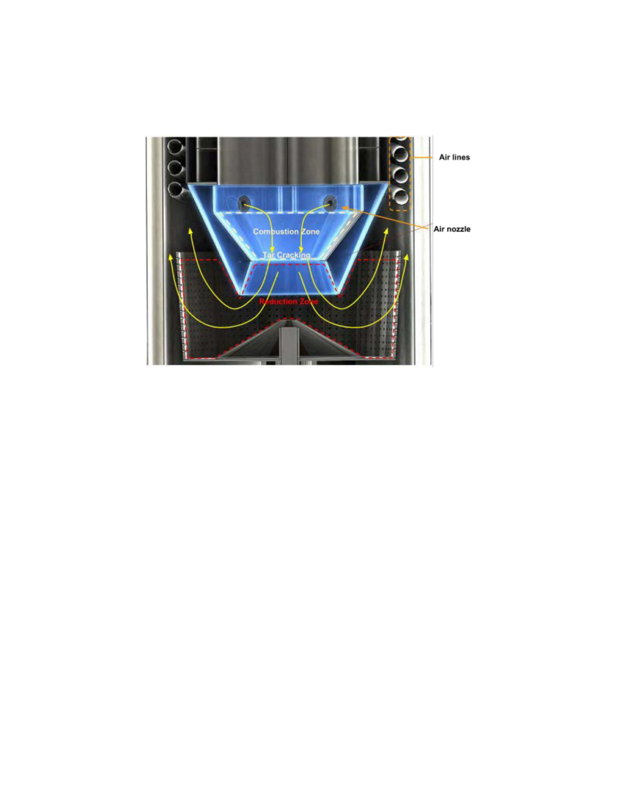
2.3 Combustion and tar cracking
Ccharcoal, tar gases + O2 → CO2 (g) + H2O (g) + heat
tar gases + heat → CO + H2
Following pyrolysis, the tar gases descend through the combustion zone, which burns a portion
of the tar gases and the charcoal to provide heat for the rest of the processes. Tar cracking,
which is the thermal decomposition of the remaining tar gases into CO and H2 gas, happens
concurrently with combustion in the void spaces between the pieces of charcoal.
The combustion zone of the PyroReactor is the region between the air nozzles and the
restriction in the hearth (see illustrations below), which is the structure projecting out of the
bottom of the PyroReactor. A few inches above the constriction, five air nozzles provide jets of
preheated air to the combustion zone. The air is preheated to a temperature of about 600˚C
using heat recovered from the producer gas by being drawn through corrugated air lines. The
high temperature of preheating increases the efficiency of combustion, enabling the combustion
zone to achieve temperatures ranging from 1000-1300˚C in front of the air jets. The constriction
causes the temperature to homogenize across the opening, forming a 800-900˚C tar cracking
hot spot through which unburned tar gases must flow, resulting in cleaner producer gas.
Page 1-9
770-00084 Section 1_Introduction to the Power Pallet (PP20) Rev B
770-00083 Power Pallet Technician's Handbook (PP20/v1.09) Rev B
Section 1 - Introduction to the Power Pallet
Combustion is the main exothermic (heat releasing) reaction in the gasification process. Drying,
pyrolysis, reduction, and tar cracking are all endothermic (heat consuming). The Power Pallet’s
use of recovered heat from the exiting hot producer gas and engine exhaust improves the heat
balance of the overall process thus increasing conversion efficiency.
The hearth, in cross-section. Orange arrows represent gas flow paths. The quantity of gas
increases as CO and H2 are produced from the charcoal and tars. Producer gas diffuses out the
top and throughout the grate basket perimeter.
2.4 Reduction
CO2 + Ccharcoal + heat → 2 CO
H2O + Ccharcoal + heat → CO + H2
The water vapor and carbon dioxide produced during combustion react with the hot charcoal in
the reduction zone. The reduction zone begins under the constriction and extends throughout
all the charcoal in the grate basket. Due to the high reactivity of carbon above temperatures of
600˚C, carbon dioxide and water vapor are reduced (having an oxygen atom removed) to H2,
CO, and some CH4, which are clean burning gaseous fuels. This conversion of the energy-rich
solid feedstock into clean-burning flammable wood gas is the ultimate objective of gasification.
Page 1-10
770-00084 Section 1_Introduction to the Power Pallet (PP20) Rev B
770-00083 Power Pallet Technician's Handbook (PP20/v1.09) Rev B
Section 1 - Introduction to the Power Pallet
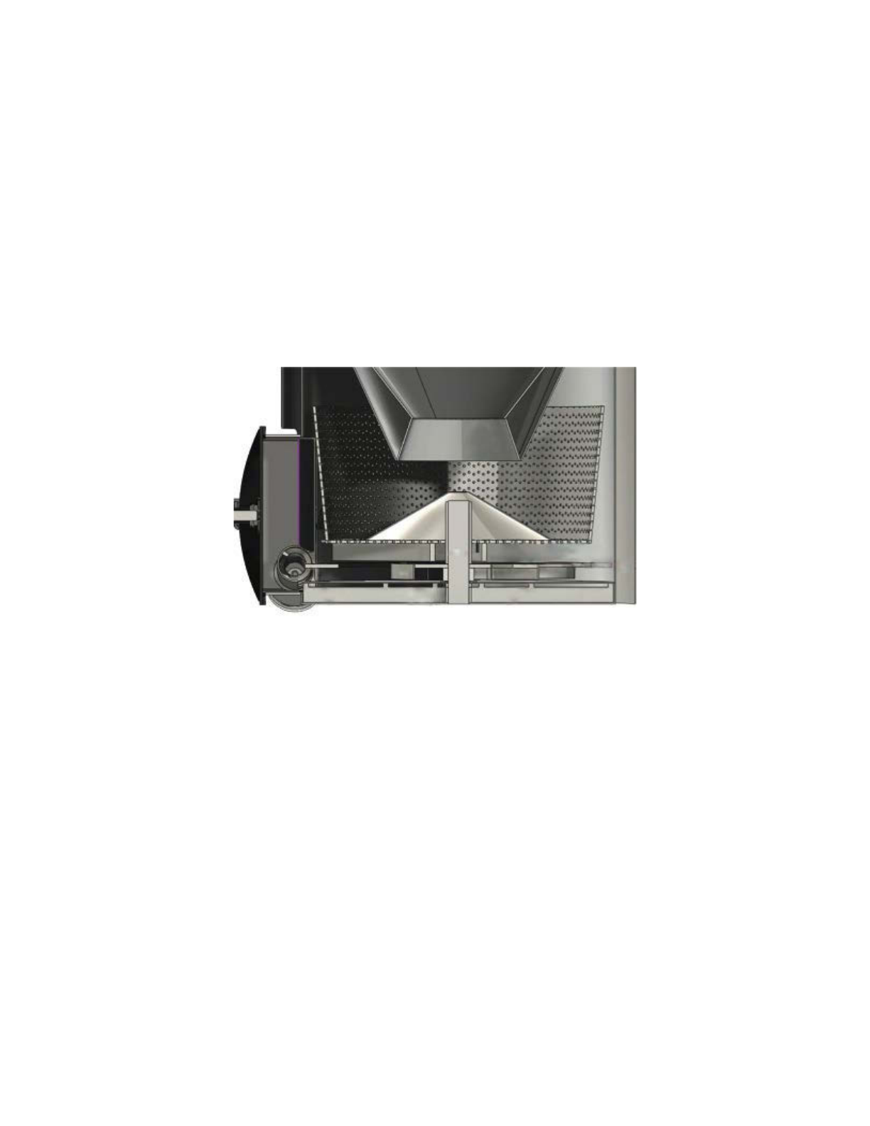
2.5 Purging char ash
In the course of the reduction reactions, the charcoal pieces are consumed to produce CO gas
and shrink and break apart until they pack densely and are rich in ash and minerals, inhibiting
the flow of gases through the hearth. These small pieces must be purged to restore gas flow.
The Power Pallet’s pressure sensors detect this condition, and automatically actuate the grate
shaker to shake the grate basket until the smallest pieces of char-ash fall onto the bottom of
the gas cowling, which is cleared by the scroll plate. The purging of these small char pieces
restores the flow of gases. The ash collection scroll then pushes the char-ash to the ash-out
auger, which pushes it into an external collection vessel that extends off the skid and resides
alongside the Power Pallet. The grate basket is the boundary of the flow of gas and the flow of
solids in the gasifier; the remaining char-ash solids are conveyed to the ash collection vessel.
The grate basket holds the charcoal chips, which react into CO gas. The basket is shaken to
purge char-ash, which inhibit gas flow as it accumulates. The pieces that shake through the
grate are moved to the ash collection vessel by the scroll and the ash-out auger.
Page 1-11
770-00084 Section 1_Introduction to the Power Pallet (PP20) Rev B
770-00083 Power Pallet Technician's Handbook (PP20/v1.09) Rev B

Section 1 - Introduction to the Power Pallet
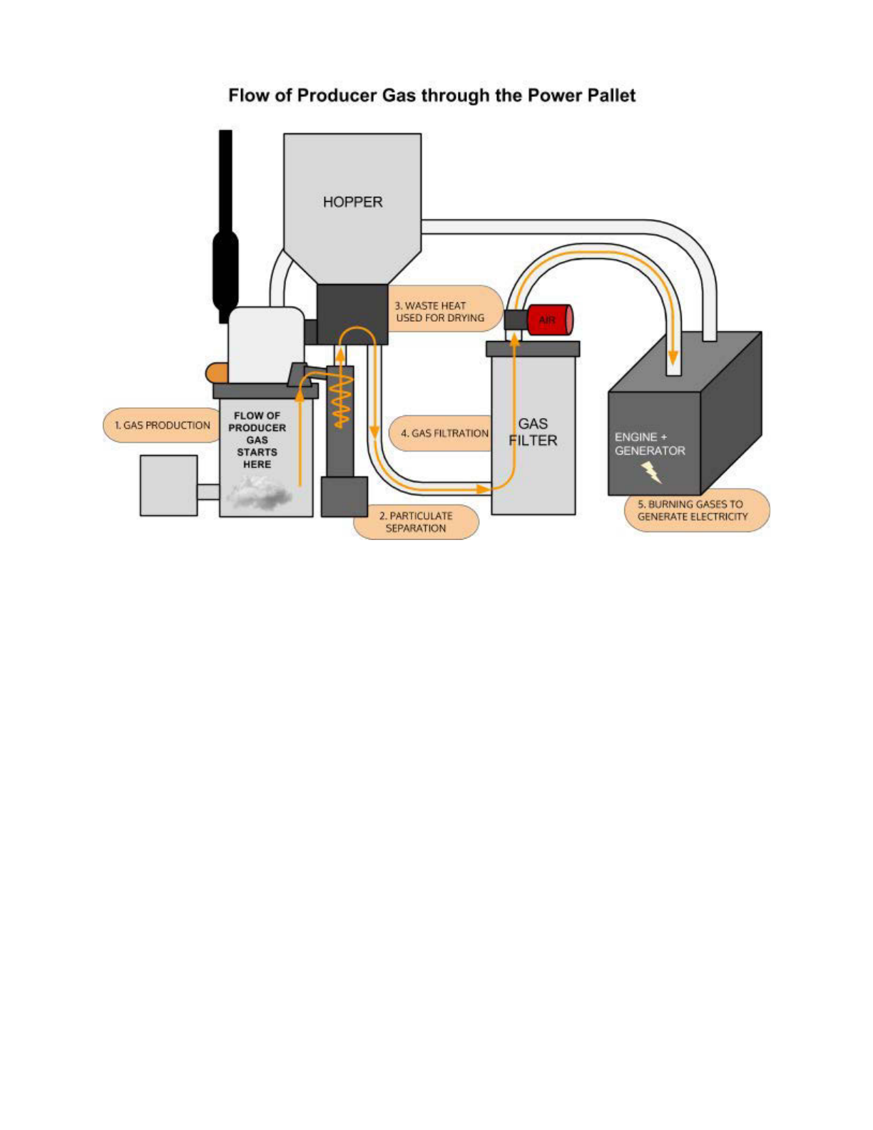
3. Flow of Gases
3.1 First stage of waste heat recovery: Preheating intake air
At the end of the reduction reaction, the producer gas is at a very high temperature and contains
a lot of recoverable heat. Many historic gasifiers pass the hot producer gas through a radiator to
dissipate excessive residual heat into the environment, but the Power Pallet recovers as much
of this heat as possible to increase its operating efficiency and the quality of the producer gas.
The hot producer gas (700˚–800+˚C) ascends through a space surrounding the PyroReactor
after percolating through the charcoal in the grate basket, exchanging heat with the air lines—
corrugated tubes through which air flows from its intake to the air nozzles in the combustion
zone. (These tubes can be seen in the cross section on the prior page. Also, see the illustration
bellow.) This process preheats the intake air flowing towards the combustion zone to about
600˚C and cools the producer gas significantly. The preheated air resulting from this process
enables the combustion zone to achieve the high temperatures with the least amount of air
used for combustion, which minimizes the amount of dilution in the producer gas. The high
combustion temperatures achieved by preheating also enhance the efficiency of tar cracking.
Together, these two benefits of this design improve the energy density of the producer gas.
Page 1-12
770-00084 Section 1_Introduction to the Power Pallet (PP20) Rev B
770-00083 Power Pallet Technician's Handbook (PP20/v1.09) Rev B
Section 1 - Introduction to the Power Pallet
Page 1-13
770-00084 Section 1_Introduction to the Power Pallet (PP20) Rev B
770-00083 Power Pallet Technician's Handbook (PP20/v1.09) Rev B

Section 1 - Introduction to the Power Pallet
A view of the internal parts of the reactor. The air lines that pre-heat intake air using heat
recovered from fresh producer gas.
3.2 Removing particulates:
Cyclonic dust separation
Producer gas entrains charcoal dust and ash as
it passes through the reduction zone. This
suspended dust must be separated so that it
does not foul the parts of the Power Pallet
downstream. Particulate removal is achieved by
the cyclone, in which the gas spins in a
descending vortex, causing the suspended dust
and ash to separate due to centrifugal force.
The producer gas then ascends out of the
cyclone through a central passage as the
particulates fall into the cyclone ash can.
3.3 Second stage of waste heat
recovery: Drying the feedstock
Page 1-14
770-00084 Section 1_Introduction to the Power Pallet (PP20) Rev B
770-00083 Power Pallet Technician's Handbook (PP20/v1.09) Rev B
Section 1 - Introduction to the Power Pallet
Despite the heat recycled into the air lines and the heat dissipated in the cyclone, the producer
gas retains enough useful heat such that this heat can be recovered by routing the gas into the
space between the double walls of the drying bucket. This second heat-exchange process cools
the gas sufficiently to be safely filtered, while also enabling the gasifier to tolerate feedstock with
a higher moisture content.
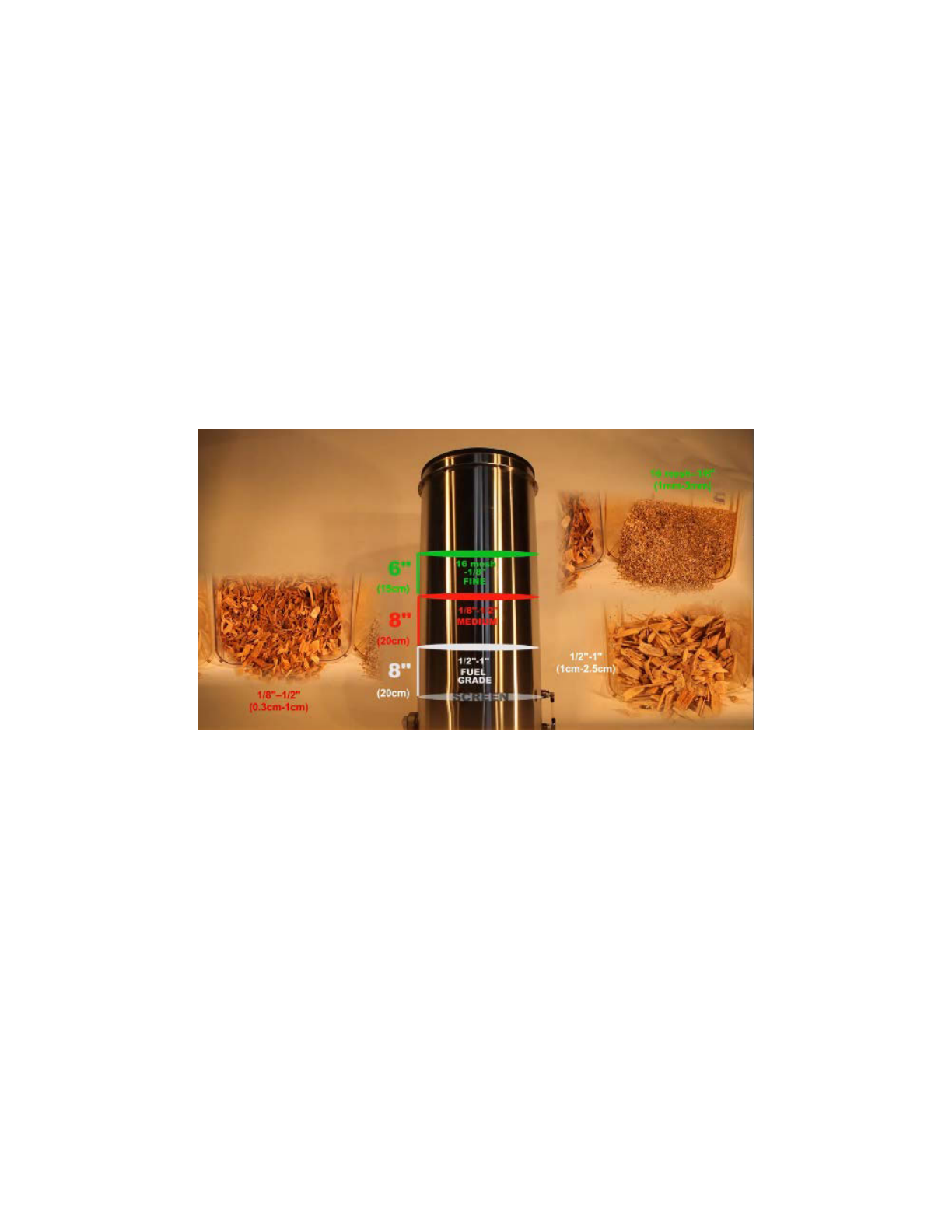
3.4 Gas filtration
Filtration is the last stage of the flow of producer gas before it is mixed with air in preparation
for combustion in the engine. Residual tar gases condense on the filter media (which consists
of sifted biomass), protecting the engine from tar build-up. The filter uses wood chips as the
filter media. A pair of oiled foam filter discs filter the fine particulates and prevent the filter media
from being entrained into the gas stream. When the filter media is being changed, the dirty
fuel-grade-sized filter media can be dried and added back into the feedstock at less than 10%
for recycling back into the system which minimizes tarry waste streams that are seen in other
gasification systems.
See section on gas filtration in Section 3.
Note: gas temperature at the base of the filter
Because the gas filter uses biomass as filter media, the maximum temperature of the gas
entering the filter must not approach pyrolysis temperatures. If the gas temperatures exceed
180˚ C, the gas is at risk of pyrolyzing the filter media, which indicates that there is probably
something wrong with the cooling process in the gas circuit, such as char ash dust fouling the
drying bucket and inhibiting heat exchange.
3.5 Air mixing
After filtration, the producer gas is mixed with air and fed to the engine for combustion.
The intake of air is regulated by an air servo controlled by a PID (proportional integral
derivative) loop run from the PCU based on input from the oxygen sensor reading the oxygen
concentration in the exhaust. This method of regulation tunes the air/fuel ratio that is optimal for
producer gas. The circular meter located on the upper right of the PCU front panel indicates the
Page 1-15
770-00084 Section 1_Introduction to the Power Pallet (PP20) Rev B
770-00083 Power Pallet Technician's Handbook (PP20/v1.09) Rev B

Section 1 - Introduction to the Power Pallet
λ (lambda) reading; lambda is the quotient of the detected air:fuel ratio and the stoichiometric
air:fuel ratio. The control loop tries to maintain a lambda of 1.05, which we have found to result
in the best combination of power and clean emissions.
λ = 1 indicates a stoichiometric mixture
λ > 1 indicates a lean mixture
λ < 1 indicates a rich mixture
The lambda meter and air mixing sub-assembly are shown above. The air mixer intakes air
at the red foam filter, introduces producer gas, and drops out condensate at the condensate
vessel. The air and fuel mixture then proceeds to the engine.
3.6 Combustion of producer gas in the engine
After mixing with air, the air-fuel mixture is drawn into the engine to be combusted for the
production of power. The entry and combustion of the producer gas into the engine is the end of
the flow of gases, and the beginning of the flow of exhaust.
3.6.1 Engine output regulated by the MPU
The Power Pallet has a direct connection between the engine’s drive shaft and the onboard
AC generator. In order for the generator to output electricity with a constant AC frequency, the
engine must be held at a specified and constant RPM, while varying the power output to match
the load on the generator. The Power Pallet achieves this stable RPM via an engine governor
which reads the RPM of the engine with a Magnetic Pick-Up (MPU) that senses the teeth on
Page 1-16
770-00084 Section 1_Introduction to the Power Pallet (PP20) Rev B
770-00083 Power Pallet Technician's Handbook (PP20/v1.09) Rev B
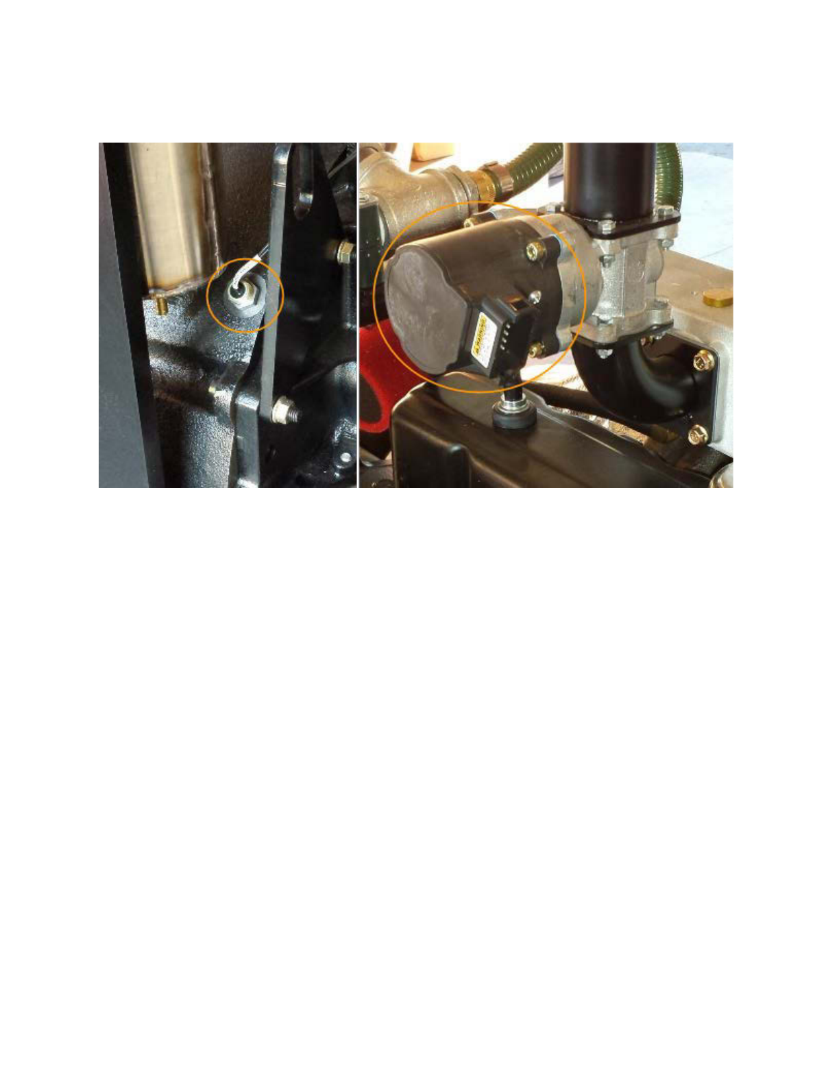
Section 1 - Introduction to the Power Pallet
the outer perimeter of the engine's flywheel. The governor then adjusts the engine's throttle to
counter any change in the RPM in response to the load thereby holding the RPM constant. This
control programming is resident in the governor and operates independently of the PCU.
The MPU is shown on the left; the engine governor is shown on the right.
3.6.2 Note: unique combustion characteristics of producer gas
Because producer gas burns much more slowly than gasoline and natural gas, the flame
front progresses much more slowly. The engine onboard the Power Pallet has its spark timing
adjusted to be optimal for producer gas, making it risky if not incompatible for use with gasoline
and natural gas. Because the Power Pallet’s spark timing is advanced too far to be operated
with gasoline, propane or natural gas without risk of engine knocking, ALL Power Labs does not
currently support multi-fuel use.
Producer gas has significantly lower energy density compared to petroleum-based fuels;
because the gasifier is aspirated with atmospheric air, which is 80% nitrogen (which is non
combustible), the resulting producer gas is diluted to a concentration of about 50-60% nitrogen
before it is even mixed with air for combustion. Secondly, the combustible molecular species in
the producer gas, CO and H2, have a significantly lower energy density than the combustible
molecular species in natural gas (methane and ethane). As a result, the energy density of
producer gas is typically about one eighth the energy density of natural gas, and engines using
this gas have a de-rated power output compared to their ratings for petroleum-based fuels.
Page 1-17
770-00084 Section 1_Introduction to the Power Pallet (PP20) Rev B
770-00083 Power Pallet Technician's Handbook (PP20/v1.09) Rev B

Section 1 - Introduction to the Power Pallet
4. Flow of Exhaust
4.1 Third stage of waste heat recovery: Exhaust-heat assisted
pyrolysis
The engine's exhaust gases are in the range of 400˚-600˚C, which is ideal for driving pyrolysis
while not being so high as to cause the formation of refractory tars that are difficult to crack.
Rather than let this energy go to waste, the Power Pallet routes the exhaust between the double
walls of the PyroReactor so that this exhaust heat can be used to pyrolyze the feedstock at the
desired temperatures. It is important to note that the exhaust does not mix with the feedstock; it
simply exchanges heat through the inside walls of the PyroReactor. After the exhaust has given
up its useful heat, it is released into the atmosphere via the exhaust pipe.
When woody biomass is exposed to lower pyrolytic temperatures (400˚–600˚C) for an extended
period of time, the resulting pyrolysis produces primary tars, which are more susceptible to
thermal cracking, resulting in cleaner gas. The PyroReactor of the v5.0 GEK gasifier used on
the Power Pallet has a significantly extended pyrolysis zone, achieving complete pyrolysis in the
ideal temperature range, enhancing the energy density and quality of the gas.
Page 1-18
770-00084 Section 1_Introduction to the Power Pallet (PP20) Rev B
770-00083 Power Pallet Technician's Handbook (PP20/v1.09) Rev B

Section 1 - Introduction to the Power Pallet
5. Automation
The Power Pallet’s automation system has a series of pressure, temperature, current, and
oxygen sensors, and other sensors that are monitored by the Process Control Unit (PCU).
The PCU runs on the open-source Arduino software platform. The PCU automatically controls
the various physical functions required to keep the system running smoothly. These functions
include:
● grate shaking, to maintain the flow of feedstock and to purge small char particles from
the gasifier bed
● augering the feedstock into the system as needed
● adjusting the air-fuel mixture for the engine to ensure complete combustion of the
producer gas, resulting in high efficiencies and clean emissions
● triggering an alarm if any events of concern arise
The PCU also allows for data-logging, additional input/output capability as well as the ability to
modify the open-source code for research, development and customizations. This automation
system is what makes the GEK gasifier system practical for use with a generator, managing the
various parameters which would otherwise need continuous operator intervention. See Section
4: Automation Assembly for details.
Page 1-19
770-00084 Section 1_Introduction to the Power Pallet (PP20) Rev B
770-00083 Power Pallet Technician's Handbook (PP20/v1.09) Rev B

Section 1 - Introduction to the Power Pallet
6. Identifying Power Pallet components
Exhibit A: Front view
Label Description Label Description
1Hopper 6Operation panel
2Valves to flare and engine 7Generator
3PCU panel 8Wiring configuration box
4Ash collection vessel 9Grid tie controler
5Gas filter
Page 1-20
770-00084 Section 1_Introduction to the Power Pallet (PP20) Rev B
770-00083 Power Pallet Technician's Handbook (PP20/v1.09) Rev B
Table of contents
Other All Power Labs Industrial Equipment manuals


Popular Industrial Equipment manuals by other brands

AstroNova
AstroNova Trojanlabel Trojan T2-C Service guide

SPX
SPX Power Team HNS150A Parts List, Assembly, and Operating Instructions

Renishaw
Renishaw PH20 Installation and user guide

Nussbaum
Nussbaum TC instruction manual

Finn
Finn T90-II HydroSeeder Operator's manual

Bungard
Bungard EXP3040LED instructions


