Operating guide
TUBE-Light Digital control panel May-22
www.allltd.uk.com
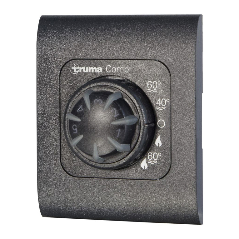
Button functions
Turn to Adjust // Press-to-set
Adjustment dial, used in conjunction with several of the features (located at bottom right)
Lights will remain OFF until a new command has been manually provided
Lights on Auto (run programme)
Manual control (override)
Allows adjustment of the light level manually - use ADJUST-SETTINGS to adjust the levels
Lights will remain ON-FULL until a new command has been manually provided
Switch individual lighting lanes ON/OFF
Set the clock - use ADJUST-SETTINGS turn dial to adjust then “PRESS” to SET the new time
Programme Buttons (4x)
Each programmes across all lanes
(no individual lane time setting)
Set programme, times & light levels (Timer buttons carry 3x features as follows)
A. Set Time/s PRESS-HOLD (3 sec’s) use ADJUST-SETTINGS - “PRESS” to SET
B. Adjust Light/Power QUICK-PRESS use ADJUST-SETTINGS - “PRESS” to SET
C. Clear Times PRESS-HOLD (3 sec’s) repeat PRESS-HOLD (3 sec’s) – timer cleared
Set programme
Step 1 TIME/SET Button - push button until activated (button turns GREEN) - LCD top screen time display will flash “00.00”
Adjust with the “ADJUST SETTINGS” turn Dial - then set the hour by PRESSING the dial - repeat for the Minutes
Step 2 TIMER A Button (other Timer buttons only if required)
Set Programme In the event of error, simply wait the unit will self-cancel “or” You can clear a timer, see TIMER button function point “C” in above grid
Set the programme times as follows (example TIMER-A)
Press & Hold for approx 3 seconds, button will activate - The lower LCD screen “Hour & Minute” display will FLASH “”00.00””
Showing 00.00 Top digits ON-Time Hour & Minutes > Set with Adjust Settings > Then PRESS to SET - move to >
Showing 00.00 Lower digits OFF-Time Hour & Minutes > Set with Adjust Settings > Then PRESS to SET - move to >
00 (Light level) Light level setting - bottom left of lower LCD screen > Set with Adjust Settings > Then PRESS to SET - move to >
0.0 (Fade Rate) Dusk-Dawn bottom right of LCD lower screen > Set with Adjust Settings > Then PRESS to SET - Finished
Settings: HO = instant light (no fade) // 0 = 10 second (quick fade) // 1-60 minutes fade - adjustable
Timer-A is now set - If more programmes are required, repeat above process using TIMER B, C, D
.
Lighting Lanes 4x lighting lane, with individual ON/OFF control switches. Any lighting lanes not required can be switched OFF (button turns RED / Stand-by)
Note; TIMER (A,B,C,D) settings work across all the lighting lanes (they do not control individual lanes).
Turning OFF places the lighting units/lanes on standby mode, power is still present (to turn the system off fully - isolate the mains supply).
*
Quick bypass Quick access to Lighting Level (power-level) change is possible , without having to re-programme the system…
Simply QUICK-PRESS the desired TIMER (A,B,C,D) button, the Lighting Power level within that programme LCD screen will “FLASH” – adjust
the level using the ADJUST-SETTING turn-dial, once the correct power level is reached PRESS the turn-dial to SAVE this new level.
*
Remote timer Remote Timer operates via TIMER-D (only one light level is available via the use of a remote timer).
(if required) Signal cable connection point on the Digi Control Panel (PCB) - A remote timer overrides all programmes when active “ON” (signal make)
LIGHT LEVEL Utilise TIMER D for the required remote timer LIGHTING/POWER level
FADE RATE Utilise TIMER D for the required FADE setting (Dusk-to-Dawn)
TIMER D It’s advised that you turn off/remove any set times with TIMER-D (this to avoid time conflicts).
Digital Panel Link cable between digital panel & PSU housing is supplied (7x core - 1.5mm)
(control) 12v supply Link to PSU Housing is required: V+ / V-
Signal cable/s Link to PSU housing, Lighting Lanes signal 1,2,3,4 & Common ground
*Cable connection points are clearly marked within both panels.
PSU Housing Mains connection 230/240v - Always connect mains supply to the Isolation switch
(power housing) Connect Digi Panel 12v power supply - connect to the indicated termination points
“ Signal cables - connect to the indicated termination points
Lighting lane POWER - Connect to the indicated termination point: +V x2 / -V x2
Lighting lane SIGNAL - Connect to the indicated termination point: Signal
Notes: Shed size: 100< metres (or less) 1.5mm core - 100> metres (or more) 2.5mm core
5 core cable is required, the Lighting lanes require a ring (loop), returning the +V / -V supply cables
Signal cables don’t require a return cable, terminate the signal cable at the last lighting unit.
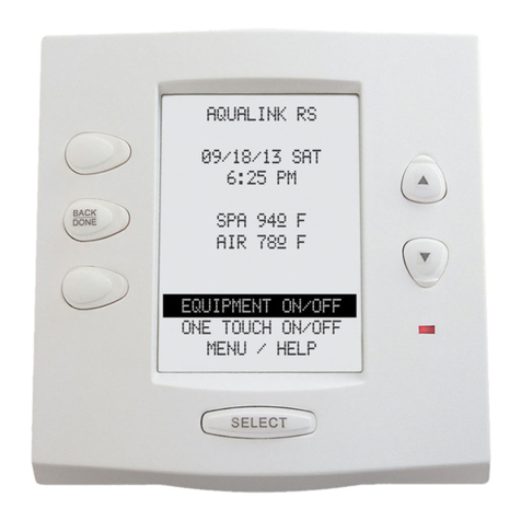
*Max distance possible between Digital Panel & PSU Housing 5m *Pic of Digital panel
It’s recommended that an appropriate power protection is fitted on install, to help protect the equipment from possible power surges or component failures.
WARNING !!
System remains LIVE (on stand-by) when turned off via the digital control panel buttons.
Mains 230/240v power should be connected to the Isolation switch on installation.
You should never open any part of this system without first SWITCHING OFF the MAINS POWER SUPPLY.
