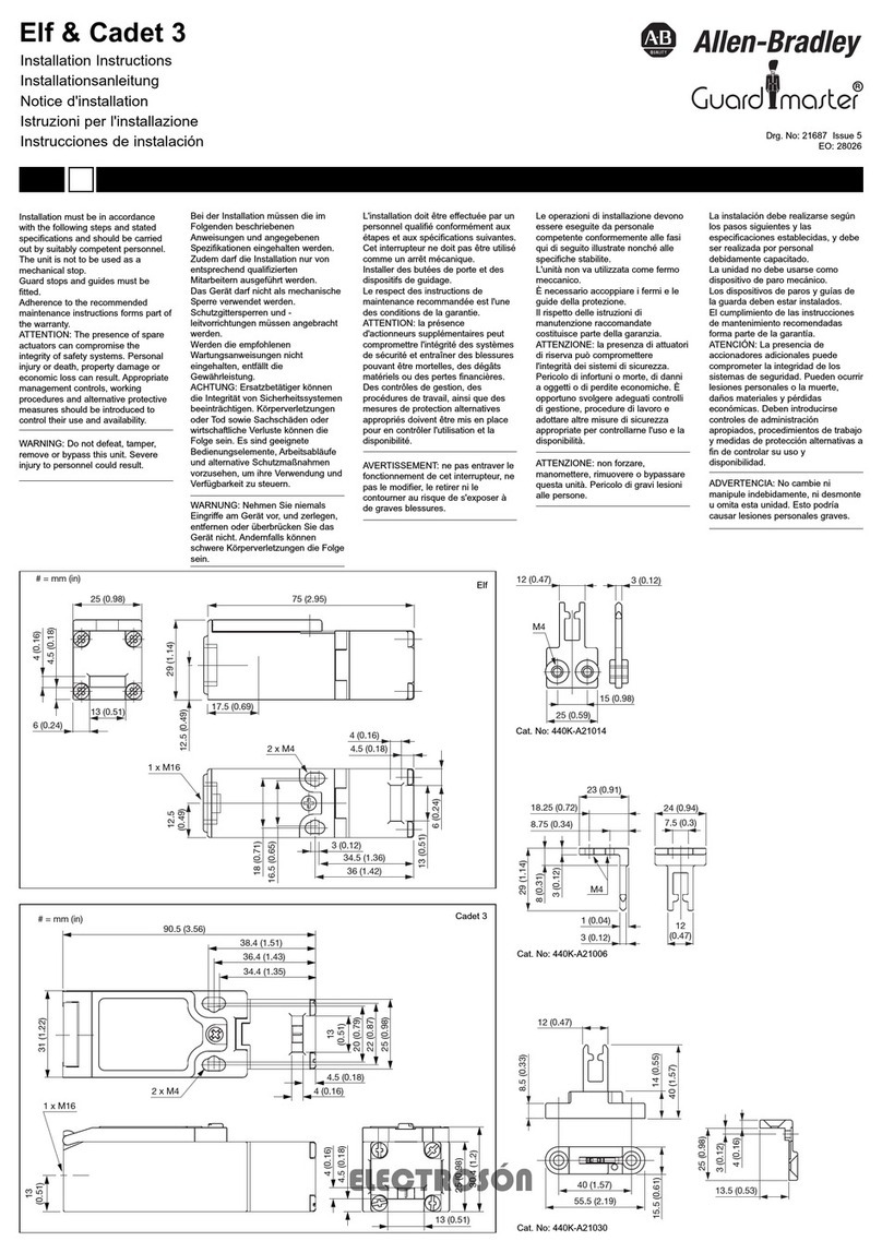
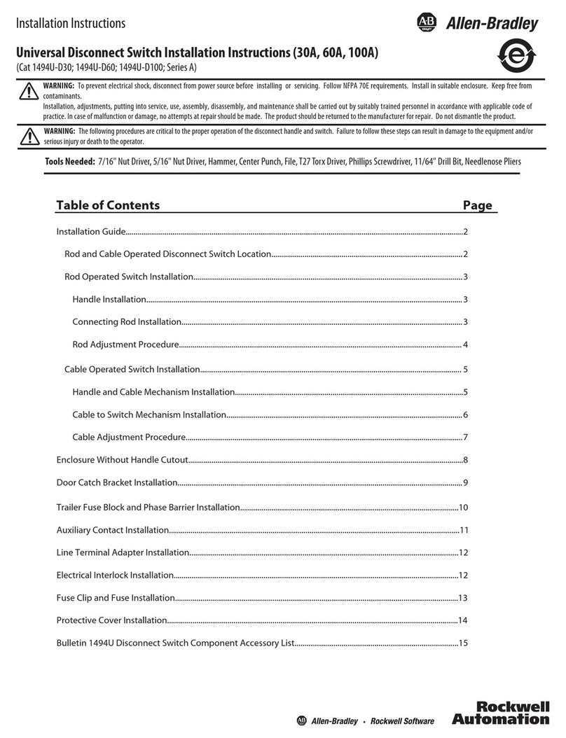
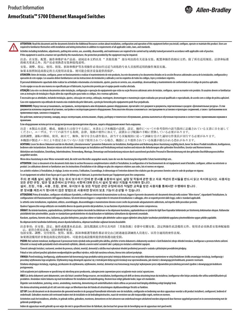
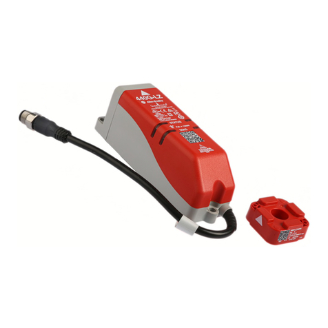
manuals.online logo
Brands
  1. Home
  2. •
  3. Brands
  4. •
  5. Allen-Bradley
  6. •
  7. Switch
  8. •
  9. Allen-Bradley GuardMaster Atlas 5-GD2 User manual

Allen-Bradley GuardMaster Atlas 5-GD2 User manual

R
www.ab.com/safety
Atlas 5-GD2
# = mm (in)
17 (0.67)
13 (0.51)163 (6.4)
184 (7.24)
5 (0.2)
30 (1.18)
56 (2.2) 3 x M20
3 x 1/2" NPT
12 (0.47)
56 (2.2)
52 (2) 4 X M5
14 (0.55)
10 (0.39)
5 (0.2)
5 (0.2)
25 (0.98)
12 (0.47)
56 (2.2)
25 (0.98)
80 (3.15)
16 (0.63)
90 (3.54)
95 (3.74)
23 (0.91)
4 (0.16)
30 (1.18)
50 (1.97) 2 x M5
10 (0.39)
Cat. No: 440G-A07136
90 (3.54)
M5
77 (3.03)
M5
75 (2.95)
10 (0.39)
24 (0.94)
9 (0.35)
18 (0.7)
21 (0.82)
Cat. No: 440G-A07269
Installation must be in accordance
with the following steps and stated
specifications and should be carried
out by suitably competent personnel.
The unit is not to be used as a
mechanical stop.
Guard stops and guides must be
fitted.
Adherence to the recommended
maintenance instructions forms part of
the warranty.
WARNING: Do not defeat, tamper,
remove or bypass this unit. Severe
injury to personnel could result.
L'installation doit être effectuée par un
personnel qualifié conformément aux
étapes et aux spécifications suivantes.
Cet interrupteur ne doit pas être utilisé
comme un arrêt mécanique.
Installer des butées de porte et des
dispositifs de guidage.
Le respect des instructions de
maintenance recommandée est l'une
des conditions de la garantie.
AVERTISSEMENT: ne pas entraver le
fonctionnement de cet interrupteur, ne
pas le modifier, le retirer ni le
contourner au risque de s'exposer à
de graves blessures.
Bei der Installation müssen die im
Folgenden beschriebenen
Anweisungen und angegebenen
Spezifikationen eingehalten werden.
Zudem darf die Installation nur von
entsprechend qualifizierten
Mitarbeitern ausgeführt werden.
Das Gerät darf nicht als mechanische
Sperre verwendet werden.
Schutzgittersperren und -
leitvorrichtungen müssen angebracht
werden.
Werden die empfohlenen
Wartungsanweisungen nicht
eingehalten, entfällt die
Gewährleistung.
WARNUNG: Nehmen Sie niemals
Eingriffe am Gerät vor, und zerlegen,
entfernen oder überbrücken Sie das
Gerät nicht. Andernfalls können
schwere Körperverletzungen die Folge
sein.
Le operazioni di installazione devono
essere eseguite da personale
competente conformemente alle fasi
qui di seguito illustrate nonché alle
specifiche stabilite.
L'unità non va utilizzata come fermo
meccanico.
È necessario accoppiare i fermi e le
guide della protezione.
Il rispetto delle istruzioni di
manutenzione raccomandate
costituisce parte della garanzia.
ATTENZIONE: non forzare,
manomettere, rimuovere o bypassare
questa unità. Pericolo di gravi lesioni
alle persone.
La instalación debe realizarse según
los pasos siguientes y las
especificaciones establecidas, y debe
ser realizada por personal
debidamente capacitado.
La unidad no debe usarse como
dispositivo de paro mecánico.
Los dispositivos de paros y guías de
la guarda deben estar instalados.
El cumplimiento de las instrucciones
de mantenimiento recomendadas
forma parte de la garantía.
ADVERTENCIA: No cambie ni
manipule indebidamente, ni desmonte
u omita esta unidad. Esto podría
causar lesiones personales graves.
Installation Instructions
Installationsanleitung
Notice d'installation
Istruzioni per l'installazione
Instrucciones de instalación
10.5 (0.41)
3.5 (0.14)
56 (2.2)
5 (0.2)
5 (0.2)
18 (0.71)
Indicator illuminates when switch is in
safe condition. Rotate and remove key to
hold Atlas 5 in unlocked mode.
Anzeiger leuchtet auf, wenn Schalter
betriebssicher ist. Drehen und den
Schlüssel herausziehen, um Atlas 5
entsichert zu halten.
Le témoin s'allume lorsque le
commutateur est en état de sécurité.
Tourner et enlever la clé pour placer
l'Atlas 5 en mode déverrouillage.
L'indicatore si accende quando il
commutatore si trova in condizione sicura.
Girare la chiave ed estrarla per tenere
l'Atlas 5 in modo sbloccato.
El indicador se ilumina cuando el
interruptor está en condiciones de
seguridad. Para mantener el Atlas 5 en
modo desbloqueado, gire y retire la llave.
123
Guard door can now be opened. Key held by
operator or in exchange system.
Schutztür kann jetzt geöffnet werden.
Schlüssel wird vom Bediener oder im
Austauschsystem gehalten.
La porte de protection peut alors être
ouverte. La clé doit être conservée par
l'opérateur ou être intégrée dans un système
d'échange.
La porta della protezione può essere ora
aperta. La chiave può essere tenuta
dall'operatore o in un sistema di scambi
predisposti.
La puerta de seguridad puede abrirse. La
llave puede ser guardada por un operario o
en un sistema de seguridad.
To restart machine, close guard, insert
key and rotate. Restart machine in
normal manner.
Zum Anfahren der Maschine Schutz
schließen, Schlüssel einstecken und
drehen. Maschine wie normal anfahren.
Pour remettre la machine en
fonctionnement, fermer la porte de
protection, insérer la clé et la tourner.
La machine doit être remise en marche
suivant la procédure normale.
Per riavviare la macchina, chiudere la
protezione, inserire la chiave e farla
girare. Riavviare la macchina nel solito
modo.
Para volver a arrancar la máquina,
cierre el protector, introduzca la llave y
gírela. Vuelva a arrancar la máquina
del modo normal.
Drg. No: 70901 Ver 13
ATLSA5-IN001A-EN-P
April 2015
6
7
43
5
8
21
A1A2
910
19 20
Atlas 5
A1A2
5
8
21
8 9 1
1
3
4
8
10
9
10
12
6 11 3
72
5 4
6
7
43
6
7
2
12
5
910
19 20
Atlas 5-GD2 QD
11mm
30mm
2 x M5
2.0 N m
(17.7 N m)
3 x M20
3 x 1/2" NPT
4 x M5
5.0 N m
(44.25 lb in)
6 x M5
2.0 N m
(17.7 lb in)
2 x M5
5.0 N m
(44.25 lb in)
≤5.5mm
=
=
1220
5/6
7/8
1/2
0mm
3/4
19 13.5
440G-A07136
440K-A07269
?300mm
?280mm
? 2° ?300mm
? 2° ?280mm
? 2° ?800mm
? 2° ?725mm
?800mm
?725mm
The Safety contact
block and Solenoid
monitor of Safety 1 may
be wired independently
by removing link
between terminals 9 &
10 and for Safety 2 by
removing link between
terminals 19 & 20.
Der Sicherheitskontaktblock
und Solenoidmonitor von
Sicherheit 1 können
unabhängig verdrahtet
werden, dazu das Glied
zwischen Klemme 9 & 10
abnehmen und bei
Sicherheit 2 das Glied
zwischen Klemmen 19 & 20
abnehmen.
Le bloc de contacts de
sécurité et le dispositif de
contrôle à noyau-
plongeur de Sécurité 1
peuvent être câblés
indépendamment en
supprimant la liaison
entre les bornes 9 et 10
et pour Sécurité 2 en
supprimant la liaison
entre les bornes 19 et 20.
Il blocco dei contatti di
sicurezza ed il dispositivo
di controllo del solenoide
della Sicurezza n. 1
possono essere cablati
indipendentemente
rimuovendo il
collegamento tra i
terminali 9 e 10, e per la
Sicurezza n. 2
rimuovendo il
collegamento tra i
terminali 19 & 20.
El bloque de contacto de
seguridad y el monitor de
solenoide de Seguridad 1
pueden conectarse
independientemente
retirando el enlace entre
los terminales 9 y 10; en
el caso de Seguridad 2,
hágalo retirando el enlace
entre los terminales 19 y
20.
Actuator and switch
must be securely
fastened onto a rigid
guard door and frame
such that the actuator
never enters the switch
at an angle below that
of the minimum
operating radius ( *2
degrees).
Do not fit actuator to
sliding concertina doors
that allow the actuator
to enter the switch at an
angle below that of the
minimum operating
radius.
Do not fit actuator to
chain.
Betätiger und Schalter
müssen an einer stabilen
Schutztür und einem
Rahmen befestigt werden,
so dass der Betätiger
niemals bei einem Winkel
unter dem des
Mindestbetriebsradius im
Schalter einrastet (* 2
Grad).
Betätiger nicht an Falttüren
befestigen, weil er sonst bei
einem Winkel unter dem
des Mindestbetriebsradius
im Schalter einrasten kann.
Betätiger nicht an einer
Kette befestigen.
L'actionneur et le
commutateur doivent être
soigneusement fixés sur
une porte de protection et
un cadre rigides de façon
que l'actionneur ne
puisse pas pénétrer dans
le commutateur à un
angle inférieur à celui du
rayon de fonctionnement
minimal (* 2°).
Ne jamais installer
l'actionneur sur une porte
coulissante en accordéon
sur laquelle il risquerait
de pénétrer dans le
commutateur à un angle
inférieur à celui du rayon
de fonctionnement
minimal.
Ne jamais installer
l'actionneur sur une
chaîne.
L'attuatore e l'interruttore
devono essere ben fissati
ad una porta e ad una
intelaiatura rigida di
protezione in modo che
l'attuatore non entri mai
nell'interruttore ad un
angolo inferiore a quello
del raggio minimo di
esercizio (* 2 gradi)
Non fissare l'attuatore su
porte scorrevoli a soffietto
che consentono
all'attuatore di entrare
nell'interruttore ad un
angolo inferiore a quello
del raggio minimo di
esercizio.
Non fissare l'attuatore ad
una catena.
El accionador y el
interruptor deben estar
bien sujetos a una puerta
de protección y su marco
correspondiente de modo
que el accionador nunca
penetre en el interruptor a
un ángulo inferior al del
radio operativo mínimo
(* 2 grados).
No instale el accionador
sobre puertas correderas
o plegables que permitan
la penetración del
accionador en el
interruptor a un ángulo
inferior al del radio
operativo mínimo.
No monte el accionador a
una cadena.
2
3
8
7
5
1
4
6
=
=
2.5
4.97.6
11/12
21/22
33/34
43/44
0mm
Jumpers on 9-10 and 19-20
Safety A
Safety A
Solenoid A Power
BBM
Solenoid A
Power
Safety B
Safety B
20
6
7
4
3
5
8
2
1
A1
A2
910
19 20
3
1
8
4
2 7
6
5
Unit must be externally grounded (use dedicated
ground point provided)
2
Check the machine is
isolated and stopped
whenever the interlocked
guard door is open.
IMPORTANT: After
installation and
commissioning, the
actuator, switch and switch
lid fixing screws should be
coated with tamper evident
varnish or similar
compound.
Compruebe que la máquina
esté parada y aislada
siempre que la puerta de
seguridad esté abierta.
IMPORTANTE: Tras la
instalación y la puesta en
funcionamiento se deberá
cubrir el accionador, el
conmutador y los tonillos de
sujeción de la tapa del
conmutador con un barniz
revelador de intentos de
apertura o producto similar.
Controllare che la macchina
sia isolata ed in condizione
di arresto ogni volta che la
porta di protezione
interbloccata sia aperta.
IMPORTANTE: dopo
l'installazione e la messa in
servizio, l'attuatore,
l'interruttore ed il coperchio
dell'interruttore devono
essere spalmati con vernice
tamper evident o una
sostanza simile.
Kontrollieren, dass die
Maschine stets isoliert und
angehalten wird, wenn die
abhängigkeitsgeschaltete
Schutzvorrichtungstür
geöffnet wird.
WICHTIG: Nach der
Installation und
Inbetriebnahme sind die
Betätigungselement-,
Schalter- und
Schalterdeckel-
Befestigungsschrauben mit
manipulation-anzeigendem
Lack oder einem ähnlichen
Mittel zu versehen.
Vérifier que la machine est
isolée et arrêtée chaque
fois que la porte de sécurité
est ouverte.
IMPORTANT :
Après l'installation et la
mise en service, les vis de
fixation de l'actionneur, du
commutateur et de son
couvercle doivent être
enduites de vernis témoin
ou d'un produit similaire.
Maintenance
Every Week
Check the correct operation of the
switching circuit. Also check for signs
of abuse or tampering. Inspect the
switch casing for damage. Of
particular importance is damage which
causes loss of sealing at the lid or
conduit entry.
At least every 6 months
Isolate all power! Remove the lid.
Inspect all terminals for tightness.
Clean out any accumulation of fine dirt
etc. Check for any sign of wear or
damage, e.g. cam assembly wear,
contact oxidisation and replace if
apparent. Replace covers & tighten
screws to specified settings. Reinstate
the power & check for correct
operation. Re-apply tamper evident
varnish or similar compound to fixings.
Repair
If there is any malfunction or damage,
no attempts at repair should be made.
The unit should be replaced before
machine operation is allowed.
DO NOT DISMANTLE THE UNIT.
Information in regard to UL508
When used in elevated ambients,
temperature rating of field wiring shall
not be less than ambient.
Use copper conductors only. Use
polymeric conduit only. Use one
conduit entrance for field connections.
Wartung
Jede Woche
Auf ordnungsgemäße Funktion des
Schaltkreises kontrollieren. Außerdem
auf Anzeichen von Missbrauch oder
Manipulation untersuchen. Das
Schaltergehäuse auf Beschädigung
kontrollieren. Dabei ist besonders auf
Beschädigungen zu achten, die
Undichtigkeit am Deckel oder
Kabelrohreingang verursachen
könnten.
Mindestens alle 6 Monate
Alle Stromversorgungen trennen! Den
Deckel abnehmen. Alle Klemmen auf
Festigkeit kontrollieren. Etwaige
Ansammlungen feiner
Schmutzteilchen etc. entfernen. Auf
Anzeichen von Verschleiß und
Beschädigungen untersuchen, z.B.
Nockenbaugruppenverschleiß oder
Kontaktoxidation, und ersetzen, wenn
diese aufgetreten sind. Deckel wieder
anbringen & Schrauben auf die
vorgegebenen Werte anziehen. Strom
wieder anschließen & auf
ordnungsgemäßen Betrieb
kontrollieren. Manipulation-
anzeigenden Lack oder ein ähnliches
Mittel neu auf die Befestigungsteile
auftragen.
Reparatur
Bei Fehlfunktion oder Beschädigung
dürfen keine Reparaturversuche
unternommen werden. Die Einheit
muss ersetzt werden, bevor weiterer
Betrieb der Maschine zugelassen
wird.
DIE EINHEIT DARF NICHT
AUSEINANDERGEBAUT WERDEN.
Information betreffs UL508
Bei Einsatz in höheren
Umgebungstemperaturen darf die
Nenntemperatur für die
Feldverdrahtung nicht niedriger sein
als die Umgebungstemperatur.
Nur Kupferleiter benutzen. Nur
polymerische Leitungsrohre benutzen.
Einen Leitungsrohreingang für die
Feldanschlüsse benutzen.
Maintenance
Toutes les semaines
Vérifier le bon fonctionnement du
circuit de commutation. Chercher
également les signes d'un éventuel
tripatouillage. Vérifier l'état du boîtier,
en particulier au niveau de l'étanchéité
du couvercle ou de l'entrée du
conduit.
Tous les 6 mois au minimum
Couper l'alimentation ! Déposer le
couvercle. Vérifier le serrage de
toutes les bornes. Éliminer la
poussière, etc. Vérifier l'état et l'usure
(usure de la came, oxydation des
contacts, etc.) et remplacer si
nécessaire. Remettre les couvercles
en place en serrant les vis au couple
spécifié. Rétablir l'alimentation et
vérifier le bon fonctionnement.
Appliquer sur les vis une nouvelle
couche de vernis témoin ou de tout
autre produit similaire.
Réparation
En cas de défaut de fonctionnement
ou d'endommagement, ne jamais
essayer de réparer le dispositif. Il doit
être remplacé avant de remettre la
machine en service.
NE JAMAIS DÉMONTER LE
DISPOSITIF.
Informations relatives au dispositif
UL508
Lorsque le dispositif est utilisé dans
des températures ambiantes élevées,
le câblage utilisé doit être prévu pour
supporter des températures
supérieures à celle de l'application.
Utiliser des conducteurs en cuivre
uniquement. Utiliser des conduits en
polymère uniquement. Utiliser une
seule entrée pour la connexion sur
site.
Manutenzione
Ogni settimana
Controllare che il circuito di
commutazione funzioni come
richiesto. Sincerarsi anche che non
esistano indicazioni di un uso non
autorizzato o di manomissioni.
Esaminare l'involucro dell'interruttore
per verificare che non sia
danneggiato. È di particolare
importanza ogni danno che possa
determinare la perdita della tenuta sul
coperchio o all'ingresso del tubo
protettivo.
Almeno ogni 6 mesi
Isolare tutte le alimentazioni di
corrente! Rimuovere il coperchio.
Controllare che tutte le morsettiere
siano ben strette. Rimuovere ogni
traccia di polvere ecc. che si sia
accumulata. Sincerarsi che non
esistano segni di usura o danno, ad
es. usura del gruppo camme,
ossidazione dei contatti, e sostituire in
caso di usura o danno. Rimettere al
loro posto i coperchi e serrare le viti
con le coppie specificate. Riconnettere
l'alimentazione elettrica e verificare il
corretto funzionamento. Applicare
nuovamente vernice tamper evident o
un composto simile ai punti di
fissaggio.
Riparazione
In caso di funzionamento anomalo o
di danno, non si deve cercare di
effettuare una riparazione. L'unità
deve essere sostituita prima di
ricominciare a far funzionare la
macchina.
NON SMONTARE L'UNITÀ.
Informazioni su UL508
Per un utilizzo in temperature
ambientali elevate, il cablaggio di
campo dovrà essere dimensionato per
limiti d'impiego a temperature non
inferiori a quelle ambientali
Utilizzare solo conduttori di rame.
Utilizzare solo tubi protettivi polimerici.
Utilizzare una entrata del condotto
protettivo per le connessioni di campo.
Mantenimiento
Cada semana
Compruebe que el circuito de
conmutación funciona correctamente.
Compruebe también que no haya
signos de uso incorrecto o
manipulación no autorizada.
Compruebe que la carcasa no
presente daños. Fíjese especialmente
de que no haya daños que pudieran
provocar una pérdida de estanqueidad
en la tapa o la entrada del conducto.
Cada 6 meses, como mínimo
Aísle toda entrada de corriente. Retire
la tapa. Compruebe el ajuste de todos
los terminales. Limpie cualquier
acumulación de polvo, etc.
Compruebe si hubiera signos de
desgaste o daños en el conjunto de la
leva, óxido en los contactos, etc., y
haga los cambios pertinentes. Vuelva
a colocar las tapas y apriete los
tornillos con los ajustes
correspondientes. Vuelva a conectar
la toma de corriente y compruebe que
funciona correctamente. Vuelva a
aplicar a las sujeciones un barniz
revelador de intentos de apertura o
compuesto similar.
Reparación
Si hubiera algún defecto o avería, no
intente repararlos. Sustituya la unidad
antes de autorizar el funcionamiento
de la máquina.
NO DESMONTE LA UNIDAD.
Información referente a UL508
Si se utiliza en entornos elevados, la
temperatura efectiva del cableado del
inductor no deberá ser inferior a la
temperatura ambiente.
Use solamente hilos conductores de
cobre. Use solamente conductos
poliméricos. Use una entrada de
conducto para las conexiones
inductoras.
3
English
Deutsch
Français
ESPAÑOL
Italiano
Safety Contacts 2 N.C. direct opening action
Designation / Utilization Cat. B300 / AC-15
240V / 1.5 A, 120V / 3 A
Thermal Current 10 A
Current, Min. 5V 5 mA dc
Auxiliary Contacts 2 N.O.
Ingress Protection Rating IP65
Operating Temperature (–10 °C+60 °C), (14 °F+140 °F)
Mechanical Life 1,000,000 operations
Electrical Life 1,000,000 operations
Torque Settings, Max.
5.0 N•m (44.25 lb•in) fixing bolts
2.0 N•m (17.7 lb•in) lid screws
1.0 N•m (8.85 lb•in) terminal screws
0.79 N•m (6.99 lb•in) terminal block
Note: The safety contacts of these products are described as normally closed (N.C.), ie. with
the guard closed, actuator in place (where relevant) and the machine able to be started.
Actuator Holding Force, Max. 5000 N (1130 lb)
Actuation Speed, Max. 160 mm (6.29 in) per second
Power Supply 24V ac/dc or 110V ac or 230V ac
Contacts de sécurité 2 N.C. ouverture directe
Désignation/utilisation B300 / AC-15
240V / 1.5 A, 120V / 3 A
Intensité thermique 10 A
Intensité minimale 5V 5 mA dc
Contacts auxiliaires 2 N.O.
Protection IP65
Plage de températures de service –10 °C+60 °C
Durée de vie mécanique 1 million de cycles
Durée de vie électrique 1 million de cycles
Couples de serrage
Vis de fixation 5,0 Nm
Vis du couvercle 2,0 Nm
Vis des bornes 1,0 Nm
Boulons à tête 0,79 N•m
Remarque : Les contacts de sécurité de ces produits sont décrits comme normalement fermés
(NF), c'est-à-dire lorsque la protection est fermée, l'actionneur en place (si applicable) et la
machine en état de démarrer.
Force de maintien maxi. de l'actionneur 5000 N
Vitesse maxi. d'activation 160 mm/s
Alimentation 24 V ca/cc ou 110 V ca ou 230 V cc
Contatti di sicurezza 2 N.C. ad azione diretta di apertura
Designazione / Cat. di utilizzazione B300 / c.a. -15
240V / 1.5 A, 120V / 3 A
Corrente termica 10 A
Corrente, min. 5V 5 mA c.c.
Contatti ausiliari 2 N.O.
Classificazione IP IP65
Temperatura d'esercizio –10 °C+60 °C
Durata meccanica 1.000.000 di funzionamenti
Durata elettrica 1.000.000 di funzionamenti
Regolazioni coppia, massima
5,0 Nm per i bulloni di fissaggio
2,0 Nm per le viti del coperchio
1,0 Nm per le viti dei morsetti
0.79 N•m per i bulloni della testa
NB: i contatti di sicurezza di questi prodotti sono descritti come normalmente chiusi (NC), vale
a dire con la protezione chiusa, l'attuatore in funzione (ove sia richiesto) e la macchina in
condizione di avviamento.
Forza di tenuta dell'attuatore, massima 5000 N
Velocità attuatore, massima 160 mm per secondo
Alimentazione elettrica 24V c.a./c.c. o 110V c.a. o 230V c.a.
Contactos de seguridad 2 N.C. acción de apertura directa
Cat. designación / utilización B300 / c.a. -15
240V / 1.5 A, 120V / 3 A
Corriente térmica 10 A
Corriente, mín 5V 5 mA c.c.
Contactos auxiliares 2 N.O.
Protección contra el ingreso IP65
Temperatura operativa (–10 °C+60 °C), (14 °F+140 °F)
Vida mecánica 1,000,000 operaciones
Vida eléctrica 1,000,000 operaciones
Ajustes de par, máx.
5.0 N•m (44.25 lb•in) tornillos de sujeción
2.0 N•m (17.7 lb•in) tornillos de la tapa
1.0 N•m (8.85 lb•in) tornillos terminales
0.79 N•m (6.99 lb•in) pernos de cabezales
Nota: Los contactos de seguridad de estos productos se describen como normalmente
cerrados (o N.C.), es decir, con el protector cerrado, el accionador en su lugar (si procede) y la
máquina en condiciones de arrancar.
Fuerza de sujeción del accionador, máx. 5000 N (1130 lb)
Velocidad del accionador, máx. 160 mm (6.29 in) por segundo
Alimentación 224V ca/cc o 110V ca o 230V ca
Sicherheitskontakte 2 N.C. direkte Öffnung
Bezeichnung / Einsatzkat. B300 / AC-15
240V / 1.5 A, 120V / 3 A
Wärmestrom 10 A
Strom, Min. 5V 5 mA dc
Hilfskontakte 2 N.O.
Eindringen-Schutzgrad IP65
Betriebstemperatur (–10 °C+60 °C), (14 °F+140 °F)
Mechanische Lebensdauer 1.000.000 Betätigungen
Elektrische Lebensdauer 1.000.000 Betätigungen
Drehmomenteinstellungen, Max
5.0 N•m (44.25 lb•in) Befestigungsschrauben
2.0 N•m (17.7 lb•in) Deckelschrauben
1.0 N•m (8.85 lb•in) Klemmenschrauben
0.79 N•m (6.99 lb•in) Kopfbolzen
Hinweis: Die Sicherheitskontakte dieser Produkte sind als normalerweise geschlossen (N.C.)
beschrieben, d.h. bei geschlossener Schutzvorrichtung, Betätigungselement in Position (falls
zutreffend) und Maschine startfähig.
Betätigungselement-Haltekraft Max. 5000 N (1130 lb)
Betätigungsgeschwindigkeit Max. 160 mm (6.29 Zoll) pro Sekunde
Stromversorgung 24V AC/DC oder 110V AC oder 230V AC
4
5Rockwell Automation ATLSA5-IN001A-EN-P – April 2015
Guard Locking Switches Installation Update
Deutsch: Sicherheitszuhaltungen – Update zur Installation
Español: Actualización de la instalación de interruptores de seguridad con bloqueo
Français: Gâches de sécurité – Mise à jour d’installation
Italiano: Interruttori per blocco protezione – Aggiornamento istruzioni per l’installazione
Original instructions in English Übersetzung der Originalanleitung Traducción de las instrucciones
originales Traduction des instructions
originales Traduzione delle istruzioni originali
English Deutsch Español Français Italiano
440G Guard Locking Safety
Switches
Sicherheitszuhaltungen der
Serie 440G
Interruptores de seguridad
con bloqueo 440G
Gâches de sécurité 440G Interruttori di sicurezza per
blocco protezione 440G
This supplement provides
information needed for ISO 14119
compliance. ENISO14119
replaces EN 1088 as the
harmonized standard for
interlocking devices associated
with guards.
This document also updates
specifications, warnings, and
application information.
Functional safety information:
http://
literature.rockwellautomation.co
m/idc/groups/literature/
documents/sr/safety-sr001_-en-
e.pdf
The products shown on this
document conform with the
Essential Health and Safety
Requirements (EHSRs) of the
European Machinery Directive.
They are third party certified to
EN 60947-5-1 (440G),
EN 60947-5-3 (440G-TLSZ and
440G-LZ) and EN ISO 14119.
Declaration of Conformity and
certification:
www.rockwellautomation.com/
certification/overview.page
Diese Ergänzung enthält Infor-
mationen, die für die Konformität
mit ISO 14119 erforderlich sind.
EN ISO 14119 ersetzt EN 1088 als
harmonisierte Norm für Verriege-
lungseinrichtungen in Verbindung
mit trennenden Schutzeinrichtun-
gen.
Dieses Dokument enthält
zudem aktualisierte Spezifika-
tionen, Warnungen und
Anwendungsdaten.
Informationen zur funktiona-
len Sicherheit: http://litera-
ture.rockwellautomation.com/
idc/groups/literature/documents/
sr/safety-sr001_-en-e.pdf
Die in diesem Dokument
dargestellten Produkte stimmen
mit den grundlegenden Gesund-
heits- und Sicherheitsanforderun-
gen der EU-Maschinenrichtlinie
überein. Sie wurden durch Dritte
gemäß EN 60947-5-1 (440G),
EN 60947-5-3 (440G-TLSZ und
440G-LZ) und EN ISO 14119
zertifiziert.
Konformitätserklärung und
Zertifizierung:
www.rockwellautomation.com/
certification/overview.page
Este suplemento proporciona la
información necesaria para el
cumplimiento de la normativa
ISO 14119. EN ISO14119 susti-
tuye a EN 1088 como norma
armonizada para dispositivos de
enclavamiento asociados a res-
guardos.
Este documento también
actualiza las especificaciones,
advertencias y la información de
aplicación.
Información de seguridad
funcional: http://
literature.rockwellautomation.co
m/idc/groups/literature/
documents/sr/safety-sr001_-en-
e.pdf
Los productos mostrados en
este documento cumplen con los
requisitos de seguridad y salud
esenciales (EHSRs) de la directiva
de maquinaria europea. Cuentan
con las certificaciones EN 60947-
5-1 (440G), EN 60947-5-3 (440G-
TLSZ y 440G-LZ) y EN ISO 14119
por parte de otros fabricantes.
Declaración de cumplimiento
normativo y homologación:
www.rockwellautomation.com/
certification/overview.page
Ce supplément fournit des
informations nécessaires pour la
conformité à la norme ISO 14119.
EN ISO 14119 remplace EN 1088
en tant que norme harmonisée
pour les dispositifs de verrouillage
avec protection.
Ce document met aussi à jour
les caractéristiques, les
avertissements et les informations
d’application.
Informations concernant la
sécurité fonctionnelle : http://
literature.rockwellautomation.co
m/idc/groups/literature/
documents/sr/safety-sr001_-en-
e.pdf
Les produits présentés dans
ce document sont conformes aux
Exigences Essentielles de Santé et
de Sécurité (EESS) de la Directive
Machines européenne. Ils sont
homologués EN 60947-5-1
(440G), EN 60947-5-3 (440G-TLSZ
et 440G-LZ) et EN ISO 14119 par
des tiers.
Déclaration de conformité et
certification :
www.rockwellautomation.com/
certification/overview.page
Questo supplemento contiene
le informazioni necessarie per la
conformità ISO 14119. La norma
EN ISO 14119 ha sostituito la
EN 1088 come norma armonizzata
in materia di dispositivi di
interblocco associati ai ripari.
Il presente aggiornamento
riguarda anche le specifiche, le
avvertenze e le informazioni
relative all’applicazione.
Informazioni sulla sicurezza
funzionale: http://
literature.rockwellautomation.co
m/idc/groups/literature/
documents/sr/safety-sr001_-en-
e.pdf
I prodotti descritti nel
presente documento sono
conformi ai Requisiti essenziali di
salute e sicurezza EHSR (Essential
Health and Safety Requirements)
della Direttiva Macchine europea.
Sono certificati da terzi in
conformità ad EN 60947-5-1
(440G), EN 60947-5-3 (440G-TLSZ
e 440G-LZ) ed EN ISO 14119.
Dichiarazione di conformità e
certificazione:
www.rockwellautomation.com/
certification/overview.page
Product
Intended Use
Bestimmungsgemäße
Verwendung Uso previsto Utilisation prévue Uso previsto
Guard
Position
Detection
Locks
Guard
Closed
Erkennung der
Schutzvorrich-
tungsposition
Schutzvorrich-
tung geschlos-
sen verriegelt
Detección
de la posición
de guarda
Bloqueo de
guarda cerrado
Détection de
position de
protection
Verrouille la
protection en
position fermée
Rilevamento
posizione
protezione
Blocco
protezione
chiusa
440G-L,
-MT, -S, -T
Actuator
inserted
into
switch
Yes Betätiger in
Schalter
eingeführt Ja Accionador
insertado en el
interruptor Sí Actionneur
intégré à
l’interrupteur Oui Attuatore
inserito
nell’interruttore Sì
440G-
TLSZ Coded
RFID
actuator Yes Codierter RFID-
Betätiger Ja Accionador
codificado por
RFID Sí Actionneur RFID
codé Oui Attuatore RFID
con codifica Sì
440G-LZ
ISO 14119 defines types of
interlocking devices and
coding:
In der Norm ISO 14119
sind die Typen der
Verriegelungseinrichtungen
und die Codierung definiert:
La normativa ISO 14119 define
los tipos de dispositivos de
enclavamiento y codificación:
La norme ISO 14119 définit les
types et le codage des
dispositifs de verrouillage :
La norma ISO 14119 definisce i
tipi di dispositivi di
interblocco e la codifica:
Product Type
Coding
Typ
Codierung
Tipo
Codificación
Type
Codage
Tipo
Codifica
Low High Niedrig Hoch Baja Alta Bas Haut Bassa Alta
440G-L,
-MT, -S, -T 2Yes – 2 Ja – 2 Sí – 2 Oui – 2 Sì –
440G-TLSZ 4Yes Yes
unique 4Ja Ja,
individuell 4Sí Sí
único 4Oui Oui
unique 4Sì Sì
univoca
440G-LZ
Discard the plastic
transit plugs (shipped with select
conduit models only) at installation
and replace with UL LIsted outlet
box plugs or the equivalent.
Entsorgen Sie bei
der Installation die Transportstecker
aus Kunststoff (nur bei bestimmten
Modellen vorhanden) und ersetzten
Sie sie durch Stecker mit UL-Appro-
bation oder durch gleichwertige
Stecker.
Deseche los
protectores de tránsito de plástico
(expedidos solo con modelos
específicos de canaleta) durante la
instalación y sustitúyalos con unos
de la caja de salida con clasificación
UL o equivalente.
Mettez au rebut
les bouchons de transport en
plastique (fournis avec certains
modèles à conduits uniquement)
lors de l’installation et remplacez-
les par des bouchons de boîtier de
sortie certifiés UL ou équivalent.
Al momento
dell’installazione, eliminare i tappi
provvisori in plastica (utilizzati
comunque solo per alcuni modelli di
fori per tubi) e sostituirli con tappi
UL Listed, o equivalenti, per fori di
scatole di derivazione.
ATTENTION
ATTENTION
ACHTUNG
ATTENTION
ATTENCIÓN
ATTENTION
ATTENTION
ATTENTION
ATTENZIONE
Publication ATLSA5-IN001A-EN-P – 70901 Ver 13 – April 2015
Copyright © 2015 Rockwell Automation, Inc. All rights reserved. Printed in the USA.
Rockwell Automation maintains current product environmental information on its website at
http://www.rockwellautomation.com/rockwellautomation/about-us/sustainability-ethics/product-environmental-compliance.page
Allen-Bradley and Rockwell Automation are trademarks of Rockwell Automation, Inc. Trademarks not belonging to Rockwell Automation are property of their respective companies.
English Deutsch Español Français Italiano
The following specifications
supersede the ratings in the existing
installation instructions.
1. Electrical life is dependent on load,
therefore, operations are not
applicable and withdrawn.
2. 440G-TLSZ and 440G-LZ: Class 2
SELV or PELV 24V DC, +10/-15%
required
3. See table:
Die folgenden Spezifikationen
ersetzen die Angaben in den
bisherigen Installationsanleitungen.
1. Die elektrische Lebensdauer ist
lastabhängig, daher sind
Betätigungen nicht maßgeblich
und werden nicht berücksichtigt.
2. 440G-TLSZ und 440G-LZ:
Schutzkleinspannung (SELV) oder
Funktionskleinspannung (PELV) der
Klasse 2, 24 V DC, +10/-15 %
erforderlich
3. Siehe Tabelle:
Las siguientes especificaciones
sustituyen las existentes en las
instrucciones de instalación previas.
1. La vida eléctrica depende de la
carga, por lo que la información
relativa a las operaciones no se
aplica y se retira.
2. 440G-TLSZ y 440G-LZ: Clase 2 SELV
o PELV 24VCC, +10/-15% requerido
3. Consulte la tabla:
Les caractéristiques suivantes
remplacent les valeurs nominales
figurant dans les instructions
d’installation existantes.
1. L’endurance électrique étant
tributaire de la charge, les
informations de cycle ne sont pas
applicables et sont retirées.
2. 440G-TLSZ et 440G-LZ : Classe 2
SELV ou PELV 24 V c.c., +10/-15 %
exigé
3. Voir le tableau :
Le seguenti specifiche sostituiscono
i valori nominali riportati nelle istru-
zioni per l’installazione precedenti.
1. La durata elettrica (numero di cicli)
dipende dal carico, pertanto non
può essere indicata preventiva-
mente.
2. 440G-TLSZ e 440G-LZ: richiesta
Classe 2 SELV o PELV 24 V CC,
+10/-15%
3. Vedere tabella:
Switch Fmax Fzh Switching Current/Voltage 3Contact Rating 6Maximum Input 7
440G-TLS* Plastic Pins 11950 N (488 lb) 1500 N (337 lb)
3 mA/18V, minimum 4
A600/AC-15 240V/3 A, 120V/6 A,
N150/DC13 125V/2.2 A
M12 QD: D150/R150 30V DC/2 A
M23 QD: B150/P150 63V DC/6 A
240V
125V
30V
63V
440G-TLS* Steel Bolts 22600 N (585 lb) 2000 N (450 lb)
440G-MT 1950 N (488 lb) 1500 N (337 lb)
440G-L Atlas 5000 N (1124 lb) 3850 N (865 lb)
440G-S Spartan 1000 N (225 lb) 770 N (173 lb)
440G-TLSZ* Plastic Pins 1950 N (488 lb) 1500 N (337 lb)
0.2 A/24V DC, maximum 52 x PNP, ON +24V DC, OFF 0V DC 24V DC440G-TLSZ* Steel BoltS 2600 N (585 lb) 2000 N (450 lb)
440G-LZ 1690 N (380 lb) 1300 N (292 lb)
1 Plastic Pins
2 Steel Bolts
3 Switching Current/Voltage
4 Minimum
5 Maximum
6 Contact Rating
7 Maximum Input
1 Kunststoffstifte
2 Stahlbolzen
3 Schaltstrom/-spannung
4 Minimal
5 Maximal
6 Schaltleistung
7 Maximaler Eingang
1 Pines de plástico
2 Pernos de acero
3 Corriente/voltaje de conmutación
4 Mínimo
5 Máximo
6 Clasificación de los contactos
7 Entrada máxima
1 Broches en plastique
2 Boulons en acier
3 Intensité/tension de commutation
4 Minimum
5 Maximum
6 Pouvoir de coupure
7 Tension d’entrée maximum
1 Perni in plastica
2 Bulloni di acciaio
3 Corrente commutabile/tensione
4 Minimo
5 Massimo
6 Portata contatti
7 Ingresso massimo
Improper selection
or installation of the devices affect the
integrity of the safety systems.
Personnel injury or death,
property damage or economic loss
can result.
Comply with ISO 14119 including
selection, accessibility to the
installation, arrangement and
fastening, possible substitute
actuation, access to the escape release,
motivation to defeat, and actuation
mode.
Management controls, working
procedures, training, and additional
protective measures should be used to
minimize the motivation to defeat and
to manage the use and availability of
spare actuators.
Comply with ISO 13857 and
ISO 13855 for guard openings and
minimum (safe) distances.
Comply with IEC 62061 or
ISO 13849-1 and ISO 13849-2 for
functional safety.
Eine falsche
Auswahl oder Installation der Geräte
wirkt sich auf die Integrität der
Sicherheitssysteme aus.
Verletzungen, Tod, Sach-
schäden oder wirtschaftliche
Verluste können die Folgen sein.
Konformität mit ISO 14119,
einschließlich Auswahl, Zugänglich-
keit der Installation, Anordnung und
Befestigung, mögliche ersatzweise
Betätigung, Zugriff auf Notentriege-
lung, Motivation zur Umgehung und
Auslösungsmodus.
Es müssen interne Arbeits-
vorschriften, Arbeitsabläufe,
Schulungen und zusätzliche Schutz-
maßnahmen eingesetzt werden, um
die Motivation für eine Systemum-
gehung zu minimieren und um die
Verwendung und Verfügbarkeit von
Ersatzbetätigern zu kontrollieren.
Konform mit ISO 13857 und
ISO 13855 hinsichtlich Öffnungen und
Mindest(sicherheits)abständen von
Schutzeinrichtungen.
Konform mit IEC 62061 sowie
ISO 13849-1 und ISO 13849-2 hinsicht-
lich funktionaler Sicherheit.
La selección o
instalación incorrecta de los dispositi-
vos afecta a la integridad de los
sistemas de seguridad.
Puede ocasionar lesiones
personales o la muerte, daños
materiales o pérdidas
económicas.
Cumplimiento con la normativa
ISO 14119 incluyendo selección, acce-
sibilidad a la instalación, disposición y
sujeción, posible actuación sustituta,
desbloqueo de escape, causas de neu-
tralización y modo de actuación.
Se debería contar con controles de
gestión, procedimientos de trabajo,
capacitación y medidas de protección
adicionales para minimizar las causas
de neutralización y para gestionar el
uso y la disponibilidad de los acciona-
dores de repuesto.
Cumplimiento con las normativas
ISO 13857 e ISO 13855 para la apertura
de la guarda y distancias de seguridad
mínimas.
Cumplimiento con las normativas
IEC 62061 o ISO 13849-1 e ISO 13849-2
para seguridad funcional.
La sélection ou
l’installation inappropriée des
dispositifs affecte l’intégrité des
systèmes de sécurité.
Il peut en résulter des blessures
corporelles pouvant être mor-
telles, des dégâts matériels ou des
pertes financières.
Le respect de la norme ISO 14119
est indispensable, y compris concer-
nant la sélection, l’accessibilité de
l’installation, le montage et la fixation,
l’utilisation possible d’actionneurs de
substitution, l’accès au déverrouillage
de secours, les motifs de contourne-
ment et le mode d’actionnement.
Les contrôles de gestion, les procé-
dures de travail, la formation et des
mesures de protection supplémen-
taires doivent être utilisés pour réduire
au minimum les motifs de contourne-
ment et pour gérer l’utilisation ainsi
que la disponibilité d’actionneurs de
rechange.
Il convient de respecter les normes
ISO 13857 et ISO 13855 pour les
ouvertures de protection et les
distances (de sécurité) minimales.
Il convient de respecter les normes
CEI 62061 ou ISO 13849-1 et ISO
13849-2 pour la sécurité fonctionnelle.
La selezione o
installazione non corretta dei
dispositivi può compromettere
l’integrità dei sistemi di sicurezza.
Pertanto, ciò potrebbe determi-
nare infortuni o decessi, danni alle
cose o perdite economiche.
Attenersi ad ISO 14119, ivi comprese
indicazioni su scelta del dispositivo,
accessibilità all’installazione, disposi-
zione e fissaggio, possibile modalità di
azionamento sostitutiva, accesso alla
funzione di sblocco, motivazioni per
l’elusione e modalità di azionamento.
Si dovranno inoltre prevedere
controlli organizzativi, procedure di
lavoro, interventi formativi e misure di
protezione supplementari al fine di
ridurre al minimo i possibili fattori che
potrebbero essere addotti quali
motivazioni per l’elusione dei
dispositivi di interblocco, e al fine di
gestire l’uso e la disponibilità degli
attuatori di riserva.
Attenersi ad ISO 13857 ed ISO 13855
per quanto riguarda le aperture delle
protezioni e le distanze (di sicurezza)
minime.
Attenersi ad IEC 62061 o ISO 13849-
1 ed ISO 13849-2 per la sicurezza
funzionale.
ATTENTION
ATTENTION
ACHTUNG
ATTENTION
ATTENCIÓN
ATTENTION
ATTENTION
ATTENTION
ATTENZIONE

Other Allen-Bradley Switch manuals

Allen-Bradley Stratix 5400 User manual

Allen-Bradley

Allen-Bradley Stratix 5400 User manual

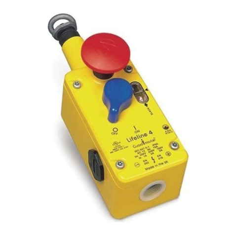
Allen-Bradley Guardmaster Lifeline 4 User manual

Allen-Bradley

Allen-Bradley Guardmaster Lifeline 4 User manual

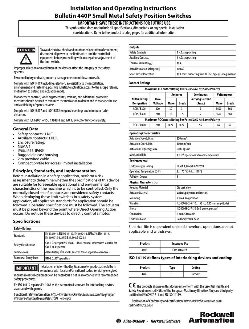
Allen-Bradley 440P User manual

Allen-Bradley

Allen-Bradley 440P User manual

Allen-Bradley 1489-AAHH3 User manual

Allen-Bradley

Allen-Bradley 1489-AAHH3 User manual

Allen-Bradley SensaGuard 440N-Z21S16A User manual

Allen-Bradley

Allen-Bradley SensaGuard 440N-Z21S16A User manual

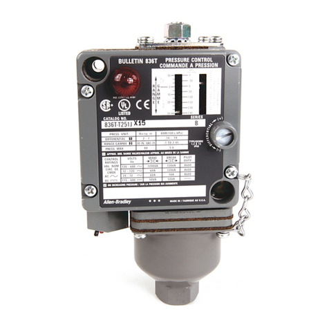
Allen-Bradley 836T Instruction manual

Allen-Bradley

Allen-Bradley 836T Instruction manual

Allen-Bradley 140M-SB User manual

Allen-Bradley

Allen-Bradley 140M-SB User manual

Allen-Bradley Stratix 8300 User manual

Allen-Bradley

Allen-Bradley Stratix 8300 User manual

Allen-Bradley 440G-TZS21UPRH User manual

Allen-Bradley

Allen-Bradley 440G-TZS21UPRH User manual

Allen-Bradley 440G-A07269 User manual

Allen-Bradley

Allen-Bradley 440G-A07269 User manual

Allen-Bradley D Series User manual

Allen-Bradley

Allen-Bradley D Series User manual

Allen-Bradley 30A User manual

Allen-Bradley

Allen-Bradley 30A User manual

Allen-Bradley TLS-GD2 User manual

Allen-Bradley

Allen-Bradley TLS-GD2 User manual

Allen-Bradley 802T User manual

Allen-Bradley

Allen-Bradley 802T User manual

Allen-Bradley 140G-M-EOP User manual

Allen-Bradley

Allen-Bradley 140G-M-EOP User manual

Allen-Bradley 140G-R Series User manual

Allen-Bradley

Allen-Bradley 140G-R Series User manual

Allen-Bradley Stratix 5700 User manual

Allen-Bradley

Allen-Bradley Stratix 5700 User manual

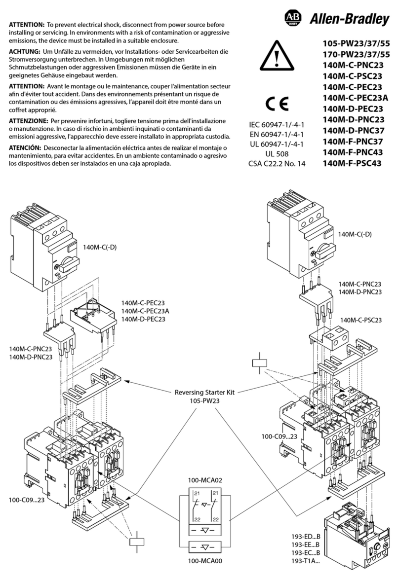
Allen-Bradley 105-PW23 User manual

Allen-Bradley

Allen-Bradley 105-PW23 User manual

Allen-Bradley Guardmaster 440K-A21014 User manual

Allen-Bradley

Allen-Bradley Guardmaster 440K-A21014 User manual

Allen-Bradley Guard master IMP Series User manual

Allen-Bradley

Allen-Bradley Guard master IMP Series User manual

Allen-Bradley 1494U-D400 User manual

Allen-Bradley

Allen-Bradley 1494U-D400 User manual

Allen-Bradley 20F Service manual

Allen-Bradley

Allen-Bradley 20F Service manual

Allen-Bradley Stratix 5400 User manual

Allen-Bradley

Allen-Bradley Stratix 5400 User manual

Allen-Bradley 194R Series User manual

Allen-Bradley

Allen-Bradley 194R Series User manual

Popular Switch manuals by other brands

Microsens MS400863M user manual

Microsens

Microsens MS400863M user manual

D-Link DGS-1005G Quick install guide

D-Link

D-Link DGS-1005G Quick install guide

Ross Synergy Q Operator's manual

Ross

Ross Synergy Q Operator's manual

PA FL3 manual

PA

PA FL3 manual

Cisco Nexus 9396PX Hardware installation guide

Cisco

Cisco Nexus 9396PX Hardware installation guide

Lantech IPGS-0204DSFP-12V user manual

Lantech

Lantech IPGS-0204DSFP-12V user manual

ENER-J Quve-060 Instruction guide

ENER-J

ENER-J Quve-060 Instruction guide

H3C S6800 Series Command reference

H3C

H3C S6800 Series Command reference

3Com 3CRDSF9PWR-US - OfficeConnect Managed Fast Ethernet PoE... user guide

3Com

3Com 3CRDSF9PWR-US - OfficeConnect Managed Fast Ethernet PoE... user guide

Manhattan 152716 instructions

Manhattan

Manhattan 152716 instructions

Dell Brocade VDX 6940 Configuration guide

Dell

Dell Brocade VDX 6940 Configuration guide

LevelOne GTL-2691 installation guide

LevelOne

LevelOne GTL-2691 installation guide

Good Way Technology TD13320 user manual

Good Way Technology

Good Way Technology TD13320 user manual

Exsys EX-62025 manual

Exsys

Exsys EX-62025 manual

Pittway System Sensor PIBVEXP Installation and maintenance instructions

Pittway

Pittway System Sensor PIBVEXP Installation and maintenance instructions

resi-linx RL-BV2100 installation manual

resi-linx

resi-linx RL-BV2100 installation manual

Cisco SFS 7024 Hardware user's guide

Cisco

Cisco SFS 7024 Hardware user's guide

ATEN MiniView CS-14 user manual

ATEN

ATEN MiniView CS-14 user manual

manuals.online logo
manuals.online logoBrands
  • About & Mission
  • Contact us
  • Privacy Policy
  • Terms and Conditions

Copyright 2025 Manuals.Online. All Rights Reserved.