Allied Radio Knight-Kit T-150 User manual

Ce
te
gg
=
knight-kit
T-150
TRANSMITTER
.
The
T-150
is
a
compact,
high-power
AM-
CW
transmitter
that's
sure
to
rate
a
place
in
your
Ham
setup.
Providing
bandswitch-
ing
coverage
of
the
80
through
6
meter
8
bands,
the
T-150
operates
at
a
power
input
waren
sont
——
i
-
of
150
watts.
Built-in
AM
modulation
is
,
provided
by
a
combination
of
screen
mod-
ulation
and
controlled
carrier.
Thus,
at
low
cost,
practically
the
equivalent
talk-power
of
plate
modulation
is
obtained.
Designed
to
provide
a
minimum
of
TVI,
¢
all
leads
going
in-and-out
of
the
cose
are
bypassed
for
RF.
There
is
more
than
ample
goin
in
the
audio
circuit
to
operote
from
any
high-impedance,
dynomic
or
crystal
microphone.
Keying
is
clean
and
chirpless
A
QWER:
ed
ATTS.
INPUT:
ON.
&
iy
Fi
-
|
with
no
hazardous
voltages
at
the
key
con-
THROUGH
10;
100
ON6
os
:
Pe
car
1
tacts.
OUTPUT
FREQUENCIES
POWER
INPUT
TO
FINAL.
~
FREQUENCY
CONTROL
+
OUTPUT
CIRCUIT
\
VFO
DRIFT
«
ACCESSORY
OUTPUTS
TUBES
*
MODULATION
*
TVI
REDUCTION
\V
MICROPHONE
INPUT
.
CW
KEYING
‘TYPES
OF
EMISSION
-
POWER
SOURCE
POWER
CONSUMPTION
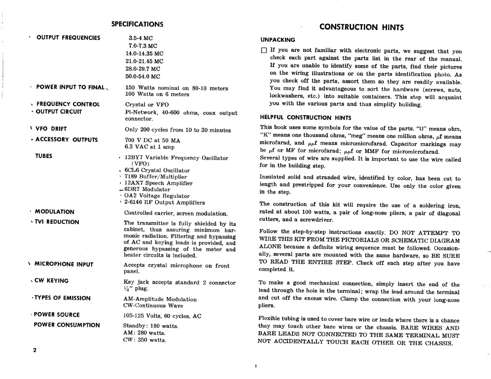
SPECIFICATIONS
3.5-4
MC
7.0-7.3
MC
14,0-14.35
MC
21.0-21.45
MC
28.0-29.7
MC
50.0-54.0
MC
150
Watts
nominal
on
80-10
meters
100
Watts
on
6
meters
Crystal
or
VFO
Pi-Network,
40-600
ohms,
coax
output
connector.
Only
200
cycles
from
10
to
30
minutes
700
V
DC
at
50
MA
6.3
VAC
at
1
amp
+
12BY7
Variable
Frequency
Oscillator
(VFO)
-
6CL6
Crystal
Oscillator
>
7189
Buffer/Multiplier
«
12AX7
Speech
Amplifier
-6DR7
Modulator
‘
OA2
Voltage
Regulator
+
2-6146
RF
Output
Amplifiers
Controlled
carrier,
screen
modulation.
The
transmitter
is
fully
shielded
by
its
cabinet,
thus
assuring
minimum
_har-
monic
radiation.
Filtering
and
bypassing
of
AC
and
keying
leads
is
provided,
and
generous
bypassing
of
the
meter
and
heater
circuits
is
included.
Accepts
crystal
microphone
on
front
panel.
Key
jack
accepts
standard
2
connector
Y,”
plug.
AM-Amplitude
Modulation
CW-Continuous
Wave
105-125
Volts,
60
cycles,
AC
Standby:
180
watts.
AM:
280
watts.
CW:
350
watts.
CONSTRUCTION
HINTS
UNPACKING
L)
If
you
are
not
familiar
with
electronic
parts,
we
suggest
that
you
check
each
part
against
the
parts
list
in
the
rear
of
the
manual.
If
you
are
unable
to
identify
some
of
the
parts,
find
their
pictures
on
the
wiring
illustrations
or
on
the
parts
identification
photo.
As
you
check
off
the
parts,
assort
them
so
they
are
readily
available.
You
may
find
it
advantageous
to
sort
the
hardware
(screws,
nuts,
lockwashers,
etc.)
into
suitable
containers.
This
step
will
acquaint
you
with
the
various
parts
and
thus
simplify
building.
HELPFUL
CONSTRUCTION
HINTS
This
book
uses
some
symbols
for
the
value
of
the
parts.
“©’’
means
ohm,
“KK”
means
one
thousand
ohms,
“meg”
means
one
million
ohms,
»f
means
microfarad,
and
ppf
means
micromicrofarad.
Capacitor
markings
may
be
pf
or
MF
for
microfarad;
pyf
or
MMF
for
micromicrofarad.
Several
types
of
wire
are
supplied.
It
is
important
to
use
the
wire
called
for
in
the
building
step.
Insulated
solid
and
stranded
wire,
identified
by
color,
has
been
cut
to
length
and
prestripped
for
your
convenience.
Use
only
the
color
given
in
the
step.
The
construction
of
this
kit
will
require
the
use
of
a
soldering
iron,
rated
at
about
100
watts,
a
pair
of
long-nose
pliers,
a
pair
of
diagonal
cutters,
and
a
screwdriver.
Follow
the
step-by-step
instructions
exactly.
DO
NOT
ATTEMPT
TO
WIRE
THIS
KIT
FROM
THE
PICTORIALS
OR
SCHEMATIC
DIAGRAM
ALONE
because
a
definite
wiring
sequence
must
be
followed.
Occasion-
ally,
several
parts
are
mounted
with
the
same
hardware,
so
BE
SURE
TO
READ
THE
ENTIRE
STEP.
Check
off
each
step
after
you
have
completed
it.
To
make
a
good
mechanical
connection,
simply
insert
the
end
of
the
lead
through
the
hole
in
the
terminal;
wrap
the
lead
around
the
terminal
and
cut
off
the
excess
wire.
Clamp
the
connection
with
your
long-nose
pliers.
Flexible
tubing
is
used
to
cover
bare
wire
or
leads
where
there
is
a
chance
they
may
touch
other
bare
wires
or
the
chassis.
BARE
WIRES
AND
BARE
LEADS
NOT
CONNECTED
TO
THE
SAME
TERMINAL
MUST
NOT
ACCIDENTALLY
TOUCH
EACH
OTHER
OR
THE
CHASSIS.
a
te
4
Oe
= |
Od
0
O) od
0
1
O)]
USE
ENOUGH
HEAT
This
is
the
main
idea
of
good
soldering.
Apply
enough
heat
to
the
metal
surfaces
you
are
joining
to
make
the
solder
spread
freely,
until
the
contour
(shape)
of
the
connection
shows
under
the
solder.
AN
ELECTRONIC
UNIT
WILL
NOT
WORK...
unless
it
is
properly
soldered.
Read
these
instruc-
ticns
carefully
to
understand
the
basic
ideas
of
good
soldering.
Enough
heat
must
be
used
so
the
solder
can
actu-
ally
penetrate
the
metal
surfaces,
making
an
un-
broken
path
over
which
electricity
can
travel,
You
are
not
using
enough
heat
if
the
solder
barely
melts
and
forms
a
rounded
ball
of
rough,
flaky
solder,
Use
the
Right
Soldering
Tool
A
soldering
iron
in
the
40-100
watt
range
is
recom-
mended,
Any
iron
in
this
range
with
a
clean,
chisel-shaped
tip
will
supply
the
correct
amount
of
heat
to
make
a
good
solder
connection.
You
may
also
use
a
solder
gun
but
make
sure
the
tip
reaches
full
heat
before
you
solder.
Keep
the
iron
or
gun
tip
brightly
coated
with
solder.
When
necessary,
wipe
the
hot
tip
clean
with
a
cloth.
lf
you
are
using
an
old
tip,
clean
it
before
you
start
soldering.
Use
a
fine
file
or
stee!
wool
to
expose
the
bright
metal.
Heat
the
iron
and
immediately
coat
the
tip
with
solder.
Use
Only
Rosin
Core
Solder
We
supply
the
right
kind
of
solder
(rosin
core
sofder).
Do
not
use
any
other
kind
of
solder!
Use
of
Acid
Core
Solder,
Paste,
or
lrons
Cleaned
on
a
Sal
Ammoniac
Block
will
ruin
any
Electronic
Unit
and
will
Void
the
Guarantee.
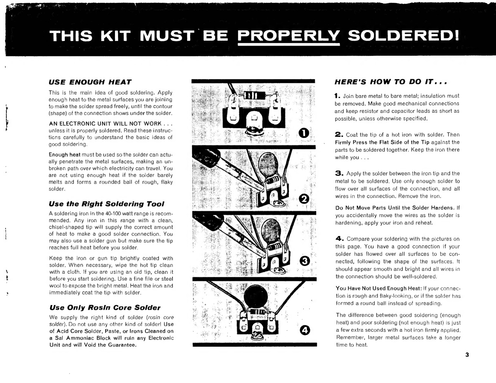
HERE'S
HOW
TO
DO
IT...
1.
Join
bare
metal
to
bare
metal:
insulation
must
be
removed.
Make
good
mechanical
connections
and
keep
resistor
and
capacitor
leads
as
short
as
possible,
unless
otherwise
specified.
2.
Coat
the
tip
of
a
hot
iron
with
solder.
Then
Firmly
Press
the
Flat
Side
of
the
Tip
against
the
parts
to
be
soldered
together.
Keep
the
iron
there
while
you...
3.
Apply
the
solder
between
the
iron
tip
and
the
metal
to
be
soldered.
Use
only
enough
solder
to
flow
over
all
surfaces
of
the
connection,
and
all
wires
in
the
connection.
Remove
the
iron.
Do
Not
Move
Parts
Until
the
Solder
Hardens.
If
you
accidentally
move
the
wires
as
the
solder
is
hardening,
apply
your
iron
and
reheat.
4.
Compare
your
soldering
with
the
pictures
on
this
page.
You
have
a
good
connection
if
your
solder
has
flowed
over
all
surfaces
to
be
con-
nected,
following
the
shape
of
the
surfaces.
It
should
appear
smooth
and
bright
and
all
wires
in
the
connection
should
be
well-soldered.,
You
Have
Not
Used
Enough
Heat:
If
your
connec-
tion
is
rough
and
flaky-looking,
or
if
the
solder
has
formed
a
round
ball
instead
of
spreading.
The
difference
between
good
soldering
(enough
heat)
and
poor
soldering
(not
enough
heat)
is
just
a
few
extra
seconds
with
a
hot
iron
firmly
applied.
Remember,
larger
metal
surfaces
take
a
longer
time
to
heat.

PARTS
MOUNTING
ON
THE
CHASSIS
CHASSIS
SEE
FIGURES
1
AND
2.
~——
rH
Position
the
chassis
as
shown
in
Figure
1.
The
following
control
and
switch
have
locating
tabs
which
are
inserted
in
the
ie
holes
in
the
chassis.
Mount
each
part
with
a
34”
nut.
8-4,
single
wafer
switch.
pase
7
R-23,
100K
control
(the
control
with
the
short
shaft).
—
fea
9-pin
tube
socket
without
center
pin
for
V-5.
Position
with
the
keyway
(the
wide
space
between
two
of
the
pins)
as
shown.
Mount
with
two
4-40
x
144”
screws,
lockwashers
and
nuts.
~—-
[gq
Four
9-pin
tube
sockets
and
four
shield
bases
for
V-1
through
V-4.
The
socket
with
the
center
pin
is
V-1.
Position
the
shield
bases
on
top
of
the
chassis
and
the
sockets
on
the
bottom
with
the
keyways
positioned
as
shown.
Mount
each
with
two
4-40
x
14”
screws,
#4
lockwashers
and
nuts
as
shown
in
Figure
3.
—_
ea
Bend
down
the
four
ground
lugs
on
each
of
the
five
sockets
mounted.
A
Ste
Ly
7-pin
tube
socket
for
V-6.
Position
with
keyway
as
shown.
Mount
with
two
4-40
x
144”
screws,
lockwashers
and
nuts.
q
SCREW
e~
HK
he
SHIELD
BASE
FIGURE
3.
SHIELD
BASE
MOUNTING
NUT
:
FUSE
HOLDER
0)
RUBBER
LOCKWASHER
WASHER
FIGURE
4.
FUSE
HOLDER
MOUNTING
em
Da
8-pin
tube
sockets
for
V-7
and
V-8,
and
two
#6
solder
lugs.
Posi-
tion
the
sockets
with
the
keyways
(notch)
as
shown.
Mount
each
socket
and
a
solder
lug
with
two
6-32
x
14”
screws,
a
lockwasher
and
tw.
“huts.
women
Large
grommet.
Mount
in
the
hole
shown.
_—
{Four
medium
grommets.
Mount
in
the
holes
shown.
~~
ta
Fuse
holder.
Position
with
the
terminals
as
shown.
Mount
as
shown
in
Figure
4.
—
Ground
post,
a
10-32
screw,
lockwasher,
nut
and
wing
nut.
Assemble
as
shown
in
Figure
5.
FIGURE
5.
GROUND
POST
ASSEMBLY

7
SCREWDRIVER
a
[]
TS-10,
4-terminal
strip.
~e
[]
TS-11,
2-terminal
strip
(near
R-23).
oe
(J
TS-15,
3-terminal
strip.
pees
(]
Mounting
plate
for
C-48.
Mount
from
inside
the
chassis
with
two
4-40
x
14”
screws,
lockwashers
and
nuts.
LOCK
RING
-
£
C-48,
40/40
uf,
450
volt
electrolytic
capacitor.
Mount
by
inserting
the
:
mounting
tabs
in
the
holes
in
the
plate.
Fasten
by
twisting
the
tabs
Y,
turn.
_
NOTE:
The
following
20
watt
resistors
are
wire
wound
stand-ups.
—_
[]
R-32,
100,
20
watt
resistor.
Mount
with
a°6-32
x
14”
screw,
lock-
washer
and
nut.
—_—
R33,
1500,
20
watt
resistor
and
TS-16,
2-terminal
strip.
Mount
with
_p
common
6-32
x
4,”
screw,
lockwasher
and
nut.
—
pet
B-37,
4K,
10
watt
resistor.
Mount
with
a
6-32
x
4”
screw,
lock-
washer
and
nut.
ae.
prt
R-34,
1500,
20
watt
resistor
and
C-47,
40
pf,
450
volt
electrolytic
FIGURE
6.
MOUNTING
J-2
capacitor.
Position
the
capacitor
with
the
leads
as
shown.
Mount
C-47
and
R-34
with
a
6-32
x
%4”
screw,
lockwasher
and
nut.
J-7,
antenna
jack.
Mount
from
outside
the
chassis
using
three
4-40
x
Connect
the
black
lead
of
C-47
to
terminal
2
of
C-48.
14,”
screws,
lockwashers
and
nuts—in
the
holes
shown.
The
fourth.
<
(J
Connect
the
red
lead
of
C-47
to
terminal
11
of
J-2.
ounting
screw
will
be
used
later
to
mount
another
part.
ris
: : ‘
:
d
;
ein
se
yu
C-46,
40uf,
450
volt
electrolytic
capacitor,
and
an
angle
clip.
Insert
a
~
J-2,
11-pin
socket.
Mount
with
a
lock
ring
as
shown
in
Figure
6.
6-32
x
1,”
screw
through
the
angle
clip
and
position
on
top
Gene
CHASSIS
oe
Oe
ae
eget
meen
ha
J-1,
8-pin
socket
and
a
#6
solder
lug.
Position
the
keyway
to
the
chassis
as
shown
in
Figure
2.
Mount
C-46
on
the
screw,
leads
posi-
|
right,
away
from
J-2.
Mount
the
socket
and
the
solder
lug
with
two
tioned
as
shown,
and
fasten
with
a
lockwasher
and
nut.
6-32
x
14”
screws,
a
lockwasher
and
two
nuts.
~—
pol
Connect
the
black
lead
of
C-46
to
terminal
1
of
C-48.,
peor
NOTE:
There
are
different
types
of
2,
3
and
5-terminal
strips
used
in
:
C
i
1
£
0-4
A
‘b
fe
the
transmitter.
When
mounting
the
terminal
strip
be
sure
to
select
the
“""
6”
[a]
Contiect
the
red:
Jead
of
20.10
terminal
2
of
R-33.
correct
type.
See
the
parts
identification
in
the
rear
of
the
manual
for
¢
gel
T-1,
power
transformer.
Position
with
the
leads
as
shown.
Mount
the
terminal
strip
identification.
*
with
four
8-32
lockwashers
and
nuts.
Le
Position
the
following
terminal
strips
as
shown.
Mount
each
with
a
6-32
x
|
1,”
screw,
lockwasher
and
nut.
|
IMPORTANT
INSTRUCTIONS
wg]
TS-1.
5-terminal
strip.
=~
g¢{]
TS-2,
standup
6-terminal
strip.
tn
THE
INSTRUCTION
CONNECT
MEANS:
Connect
the
wire
or
lead
‘
a
: :
to
the
given
point.
Make
a
firm
mechanical
connection
BUT
DO
f-7
‘€]
TS-3
and
TS-4,
two
3-torminal
strips.
NOT
SOLDER
AT
THIS
TIME.
Later
another
wire
or
wires
will
be
eal
TS-5,
3-terminal
strip.
LEE
connected
to
this
point.
—_—
vin
TS-6,
2-terminal
strip.
a
IIE
INSTRUCTION
SOLDER
MEANS:
Connect
the
wire
or
lead
TS-7,
2-terminal
strip
and
an
angle
clip.
From
the
chassis
top,
to
the
given
point
and
then
solder
the
terminal
and
all
connections
insert
the
screw
through
the
angle
clip,
the
chassis
and
the
mount-
in
it.
If
there
is
more
than
one
wire
in
the
connection,
the
amount
ing
foot
of
TS-7.
Position
the
clip
as
shown
in
Figure
2
and
fasten
—
}
will
be
stated—for
example
(2
wires).
After
soldering
a
connection
-with
a
lockwasher
and
nut.
-
trim
all
wires
as
close
as
possible
to
the
terminal.
—
TS-8,
3-terminal
strip.
a
panes
ra
TS-9,
5-terminal
strip.
NOTE:
The
transformer
leads
may
be
shortened
for
neater
connections.
5

f
:
SHOULDER
|
WASHER
el
t
i
a
CHASSIS
1
FIBER
Ce)
WASHER
“Ne
'
AD~_
scree
LUG
wr
FIGURE
7.
MOUNTING
L-18
eth
the
leads
of
T-1
as
follows:
f
Fi
is
Fi
yO
¢
,
yO
eel
+
ere
~~
Either
of
the
red
leads.
Cut
4”
off
this
lead.
Remove
1”
insulation
from
the
end.
Twist
the
strands’
together
and
coat
lightly
with
solder.
Solder
this
lead
to
terminal
2
of
R-32.
Two
black
leads.
Cut
2”
off
each
lead.
Remove
%”
of
insulation
from
each
lead.
Twist
the
stranded
wires
together
and
coat
lightly
with
solder.
Connect
one
of
the
leads
to
terminal
2
of
TS;5.
Con-
nect
the
other
lead
to
terminal
3,
of
TS-5.
,
The
other
red
leall.
Connect
to
terminal
_8
of
J-2..
Either
of
the
green
leads.
Solder
to
terminal
A
of
J-2.
The
other
green
lead.
Cut
5”
off
this
lead.
Remove
1%,”
of
the
insulation
from
the
end.
Twist
the
stranded
wires
together
and
coat
lightly
with
solder.
Connect
to
terminal
2
of
TS-4.
/
Nee
oid
Shoulder
washer,
fiber
washer,
+8
solder
lug
and
an
8-32
nut.
Assemble
as
shown
in
Figure
7.
Do
not
overtighten
the
nut
as
the
coil
form
will
be
damaged.
—
Ey
Large
L
shaped
bracket.
Mount
on
the
top
of
the
chassis
with
two
6-32
x
14”
screws,
lockwashers
and
nuts.
~—-
NOTE:
When
mounting
the
variable
capacitors,
be
sure
the
blades
are
closed
all
the
way.
yo
C-16
and
C-21,
two
variable
capacitors
(part
#£
286053).
Mount
each
with
three
6-32
x
4%”
screws
and
lockwashers.
The
lockwashers
go
under
the
screw
heads.
Bend
the
terminals
of
C-16
and
C-21
up
as
-
shown.
eye
yee
+f]
C-35,
variable
capacitor
(part
4286056).
Mount
to
the
large
L
brac-
ket
with
two
6-32
x
14”
screws
and
lockwashers.
—,
yO
C-32,
variable
capacitor
(part
3286057).
Mount
to
the
large
L
brac-
ket
with
two
8-32
screws
and
lockwashers.
Z
nee
‘¥
Control
bracket.
Mount
with
two
6-32
x
1,”
screws,
lockwashers
and
nuts.
¥]
R-16,
100K
contro!
(long
shaft).
Mount
to
the
control
bracket
with
;a
34”
lockwasher
and
nut.
TS-12,
1-terminal
strip.
Mount
with
a
6-32
x
4,”
serew,
lockwasher
and
nut.
A
ceramic
spacer,
two
#8
solder
lugs,
two
6-32
x
1.”
screws
and
lockwashers.
Fasten
the
solder
lugs
to
the
spacer
as
shown
in
Figure
8.
Fasten
the
spacer
to
the
top
of
the
chassis
near
the
rear
edge
as
shown
in
Figure
2.
CHASSIS
SCREW
FIGURE
8.
SPACER
MOUNTING
LOCATING
—
2D,
ma
&
soe
g
ce,
y
:
>,
a
Y
eee
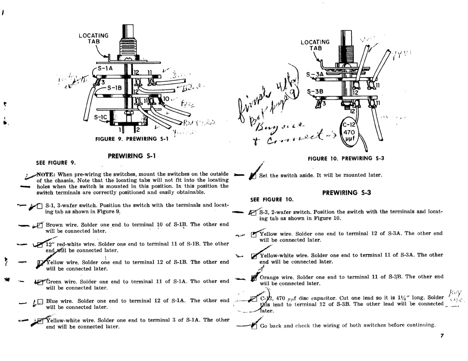
FIGURE
9.
PREWIRING
S-1
°
PREWIRING
S-1
SEE
FIGURE
9.
io
NOTE:
When
pre-wiring
the
switches,
mount
the
switches
on
the
outside
of
the
chassis.
Note
that
the
locating
tabs
will
not
fit
into
the
locating
«=e
holes
when
the
switch
is
mounted
in
this
position.
In
this
position
the
switch
terminals
are
correctly
positioned
and
easily
obtainable.
vee
S-1,
3-wafer
switch.
Position
the
switch
with
the
terminals
and
locat-
ing
tab
as
shown
in
Figure
9.
me,
oF]
Brown
wire.
Solder
one
end
to
terminal
10
of
S-1B.
The
other
end
will
be
connected
later.
a“
.
——
12”
red-white
wire.
Solder
one
end
to
terminal
11
of
S-1B.
The
other
en
ll
be
connected
later.
i
y
ice
ellow
wire.
Solder
one
end
to
terminal
12
of
S-1B.
The
other
end
will
be
connected
later.
-
aey"Green
wire.
Solder
one
end
to
terminal
11
of
S-1A.
The
other
end
will
be
connected
later.
a
LC
Blue
wire.
Solder
one
end
to
terminal
12
of
S-1A.
The
other
end
will
be
connected
later.
ellow-white
wire.
Solder
one
end
to
terminal
3
of
S-1A.
The
other
end
will
be
connected
later.
week
FIGURE
10.
PREWIRING
S-3
—
Set
the
switch
aside.
It
will
be
mounted
later.
PREWIRING
S-3
SEE
FIGURE
10.
—
LAS-3,
2-wafer
switch.
Position
the
switch
with
the
terminals
and
locat-~-
ing
tab
as
shown
in
Figure
10.
Yellow
wire.
Solder
one
end
to
terminal
12
of
S-3A.
The
other
end
ae
will
be
connected
later.
ae
Yellow-white
wire.
Solder
one
end
to
terminal
11
of
S-3A.
The
other
end
will
be
connected
later.
Namen,
Orange
wire.
Solder
one
end
to
terminal
11
of
5-3B.
The
other
end
will
be
connected
later.
heen
is
lead
to
terminal
12
of
S-3B.
The
other
lead
will
be
connected
Fh
be
back
and
check
the
wiring
of
both
switches
before
continuing.
Buy
,
470
pf
dise
capacitor.
Cut
one
lead
so
it
is
114”
long.
Solder
if
yan

/
FIRST
WIRING
ON
THE
BOTTOM
OF
THE
CHASSIS
EE
FIGURE
11.
NOTE:
Position
the
chassis
so
it
is
not
resting
on
L-18,
to
prevent
its
eet
ing
damaged.
Dire
shield
and
an
angle
clip.
Fasten
the
angle
clip
to
the
bottom
shield,
as
shown,
with
a
6-32
x
3/16”
screw
and
lockwasher.
al
S-3,
the
pre-wired
switch
and
the
bottom
shield.
Insert
the
shaft
of
S-3
through
the
bottom
shield,
the
chassis
and
fasten
on
the
outside
of
the
chassis
with
a
%”
nut.
Be
sure
the
locating
tab
enters
the
locating
hole.
Ceramic
spacer,
+wo
#8
solder
lugs,
two
6-32
x
4,”
screws
and
lock-
washers.
Place
a
lockwasher
over
one
screw
and
insert
the
screw
a
/
through
the
angle
clip
mounted
to
the
bottom
shield,
and
through
the
chassis.
Mount
the
ceramic
spacer
on
the
screw
as
it
protrudes
through
the
top
of
the
chassis.
Fasten
the
solder
lugs
to
the
top
of
the
space
and-position
as.shown
in
Figure
2.
S-1,
the
other
pre-wired
switch.
Fasten
to
the
chassis,
locating
tab
in
the
locating
hole,
with
a
34”
nut.
ne
NOTE:
Position
all
wires
as
close
to
the
chassis
as
possible.
£+t
Orange
wire.
Connect
one
end
to
ground
lug
A.
of
V-5.
Insert
the
other
end
through
the
cutout,
it
will
be
connected
later.
bal
cist
red-white
stranded
wire.
Solder
one
end
to
ground
lug
A
of
5
(2
wires).
Insert
the
other
end
through
the
cutout
shown,
it
will
i
cobnerted
later.
we
TP
a
ee
A
erean
ie
acl
meet
eine
serene
“Green
wire.
Solder
one
end
to
terminal
11,
of
S-4.
Insert
the
other
as
end
through
the
cutout
shown,
it
will
be
connected
later.
a
—
Yellow
wire.
Solder
one
end
to
terminal
10
of
S-4.
Insert
the
other
end
through
the
cutout
shown,
it
will
be
connected
later.
ans
Gray
wire.
Solder
one
end
to
terminal
9
of
S-4.
Connect
the
other
nd
to
the
solder
lug
between
V-3
and_V-
LEN
mate
0
Orange
wire.
Solder
one
end
to
o
terminal
7
of
S-4.
Connect
the
other
.
end
to
terminal
J
of
TS-10.
.
ry
range
wire.
Solder
one
end
to
pin,
4.0f,
V-5.
Connect
the
other
end
to
pin
9
of
V-4.
7
:
=
ee
|
R-28,
1
meg
resistor
(brown,
black,
green).
Insert
one
lead
through
_
pin 2
of
v‘5
and
solder
the
end
to
pin
§
of
V-5.
hoes
the
other
lead
to
terminall
of
TS-1.
a
pieces
of
small
bare
wire.
Connect
as
‘follows
:
Solder
pin
2
of
V-5.
nee
ae
wire.
Solder
one
end
to
pin
5
of
Ve.
Solder
the
other
end
to-fround
lug
C
C
of
of
V-5
~
are
wire.
Solder
one
end
to
pin
8
of
.V-5.
Solder
the
other
end
——
to
ground
lug
D
of
V-5,
/
NOTE:
There
are
two
.005
yf
dise
capacitors
rated
at
1000
volts
used
in
KX
this
kit.
They
are
stamped
IKV
and
should
only
be
used
where
specified.
(
7
The
remainder
ive
.005
pf
disc
capacitors
are
rated
at
600
volts
and
—
meee,
aan
are
unstamped.
x
,
€
of
V-2
(2
wires).
Connect
the
other
lead
to
terminal
(
one
bY
c:
49,
.005
pf
disc
capacitor.
Connect
one
lead
to
terminal
1
of_TS-1.
Connect
the
other
lead
to
terminal
2
of
TS-1.
we
yal
C-41,
1
pf
tubular
capacitor.
Solder
the
end
marked
with
a
band
to
ground
lug
/D.of.V-3.
Connect
the
other
lead
to
terminal_4
of
TS-1.
‘ellow-white
wire
from
terminal
3
of
§-1A.
Connect
the
free
end
to
terminal
5_
5_of
TS-1.
“Orange
wire.
Connect
one
end
to
pin
9
of
V-4.
Connect
the
other
end
to.pin
4
¢
of
V
V-3,
"Yellow
wire.
ire.
Connect
one
end
to
pin
4
of
V-
“3.
Connect
the
other
end
to-pin
7
of
V-
7.
WA”
féce
of
the
small
bare
wire.
Solder
one
end
to
pin
5
of
V-3.
Con-
t
the
other
end
to
ground
lug
C
of
V-3.
C-33,
.005
pf,
1000
volts
(stamped
IKV)
disc
capacitor.
Connect
one
C-52,
.005
pf
disc
capacitor.
Solder
one
lead
to
ground
lug
C
of
V-3
(3
wires).
Solder
the
other
lead
to
pin
4
of
V-3,
(3
wires).
C-20,
.005
pf
disc
capacitor.
Connect
one
lead
to
pin
3
of
V-3.
Con-
-nect
the
other
lead
to
ground
lug
A
of
V-3.
C-18,
.005
yf
disc
capacitor.
Connect
one
lead_to
pin
9
of
V-3.
Con-
nect
the
other
lead
to
ground
lug
A
of
V-3.
Samael
ST
R-
-9,
390
©,
1
watt
resistor
(orange,
white,
brown).
Solder
one
lead
to
wires).
Connect
the
other
lead
to
termina]
4
of
TS-10.
im,
n3-of.
V-3.
¥
Green
wire.
Connect
one
end
to
termipal
4
4
of
TS-10.
Contiect
the
other
end
to
terminal
5
of
T§-9.:
rae
R-15,
10
Q,
5%
1
watt
resistor
(brown,
black,
black,
gold).
Connect
ne
lead
to
terminal
2S
of
|
TS-
-8.
Solder
the
other
lead
to
the
solder
lug
(3
wires).
White
wire.
Connect
one
end
to
terminal
2
of
TS-8,
Insert
the
other
nd
through
the
cutout
shown.
Orange
wire.
Solder
one
end
to,
pin.6
of
V-2.
Connect
the
other
end
terminal
2
of
C-16
”
piece
of
the
small
bare
wire.
Solder
one
end
to
pin
7
of
MG
-2.
Connect
the
other
end
to
ground
lug
C
of
V-2.
C-51,
.005
pf
disc
capacitor.
Connect
one
lead
to
pin
5
5
of
V-2.
Solder
the
other
lead
to
ground
lug
C.
of,
V-2
(2
wires).
OTE:
The
coils
in
this
kit
are
coded
with
a
color
dot,
or,
if
encased
in
plastic,
by
the
color
of
the
case.
Coils
L-21,
L-22,
and
L-23
ne
BY
BPS
ave-no
color
dot;
or
if.
encased,
are
in
clear-
plastic}
L-23,
2.2
xh
coil.
Connect
one
lead
to
terminal
1,
of
TS-7.,
Connect
the
lead
to
pin
6
of
V-1.
C-14,
.005
pf
disc
capacitor.
Insert
one
lead
through
ground
lug
B.
of
.V-2
and
solder,to-pin
.4
of
.V.2.
Solder
ground
lug
,
B.
Connect
the
other
lead
to_pin
1
of
V-
32
R-6,
390
©
resistor
(orante:
white,
brown).
Solder
one
lead
to
pin
1.
ale
OE
ad
to
ground
lug
Co
of
V-3.
Connect
the
other
lead
to
the
e
solder
lug.
De}
é
“BR
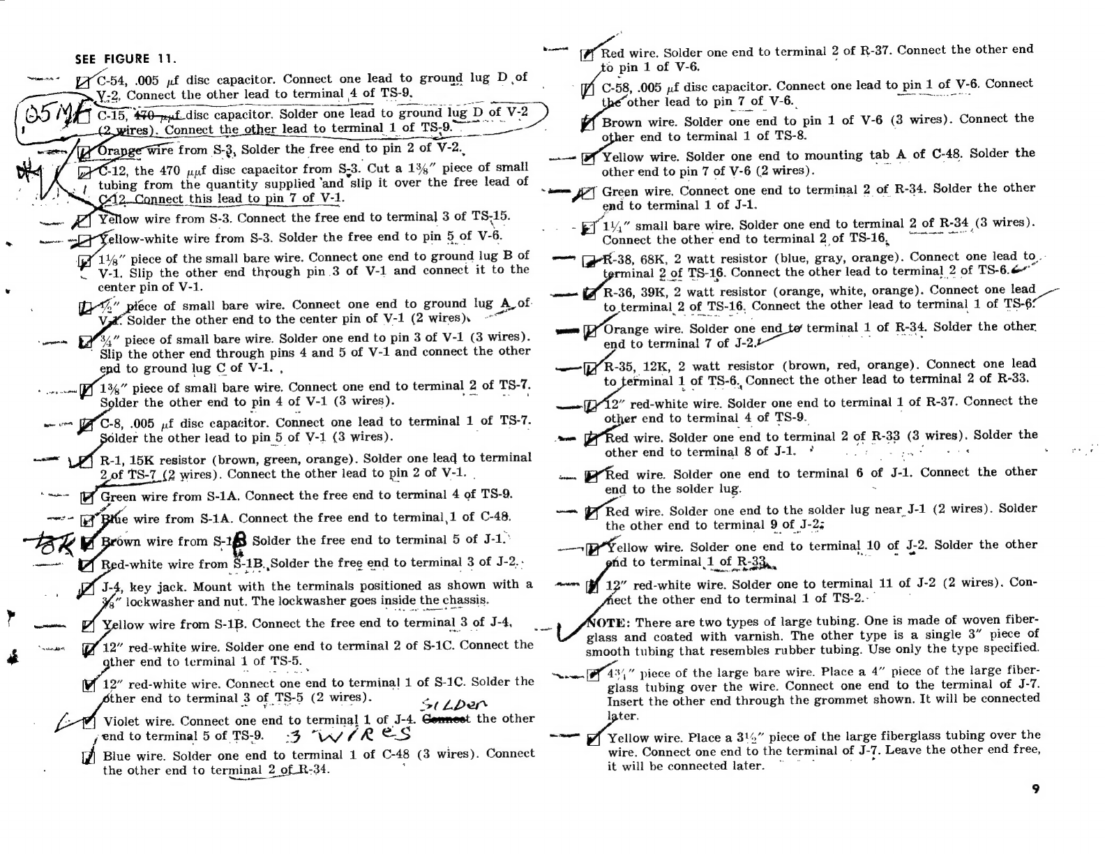
SEE
FIGURE
11.
rarer:
C54,
005
pf
disc
capacitor.
Connect
one
lead
to
ground
lug
D
of
>.Y:2,
Connect
the
other
lead
to
terminal
4
of
TS-9,
,
O51
N,
C-15,
440-puf-dise
capacitor.
Solder
‘one
lead
to
‘ground
lug
D
of
V-2
)
t
Me
eS
res).
Connect
the
other
lead
to
terminal
1
of
TS-9.
fog
nage
ae
nae,
ents
eee
rapgewire
from
S-3,
Solder
the
free
end
to
pin
2
of
V-2.,
-12,
the
470
pyf
disc
capacitor
from
$3.
Cut
a
134”
piece
of
small
bing
from
the
quantity
supplied
‘and
slip
it
over
the
free
lead
of
¥12.Connect
this
lead
to
pin
7
of
V-1.
Yellow
wire
from
S-3.
Connect
the
free
end
to
termina]
3
of
TS,15.
meee
eae
wire
from
S-3.
Solder
the
free
end
to
pin
5
of
v-6.
{p¥
1144”
piece
of
the
small
bare
wire.
Connect
one
end
to
ground
lug
B
of
*
V-1.
Slip
the
other
end
through
pin
3
of
V-1
and
connect
it
to
the
center
pin
of
V-1.
:
oe”
piece
of
small
bare
wire.
Connect
one
end
to
ground
lug
A_of.
Ene
Solder
the
other
end
to
the
center
pin
of
V-1
(2
wires).
~~
34”
piece
of
small
bare
wire.
Solder
one
end
to
pin
3
of
V-1
(3
wires).
’
Slip
the
other
end
through
pins
4
and
5
of
V-1
and
connect
the
other
end
to
ground
lug
C
of
V-1.
,
«
renew
PF
134”
piece
of
small
bare
wire.
Connect
one
end
to
terminal
2
of
TS-7.
Solder
the
other
end
to
pin
4
of
V-1
(3
wires).
re
men
ce
C-8,
.005
,f
disc
capacitor.
Connect
one
lead
to
terminal
1
of
TS-7.
sider
the
other
lead
to
pin
5
of
V-1
(3
wires).
;
,
ei
R-1,
15K
resistor
(brown,
green,
orange).
Solder
one
lead
to
terminal
2.
of
TS-7
(2
wires).
Connect
the
other
lead
to
pin
2
of
V-1.
|
cee
Green
wire
from
S-1A.
Connect
the
free
end
to
terminal
4
of
TS-9.
”
“+
[a
Bthe
wire
from
S-1A.
Connect
the
free
end
to
terminal,1
of
C-48.
aes
wire
from
ag
Solder
the
free
end
to
terminal
5
of
J-1.°
:
R
ioe
d-white
wire
from
*
-1B.,Solder
the
free
end
to
terminal
3
of
J-2.-
;
J-4,
key
jack.
Mount
with
the
terminals
positioned
as
shown
with
a
3”
lockwasher
and
nut.
The
lockwasher
goes
inside
the
chassis.
—e
Yellow
wire
from
S-1B.
Connect
the
free
end
to
terminal
3
of
J-4,
neat
a
red-white
wire.
Solder
one
end
to
terminal
2
of
S-1C.
Connect
the
one
end
to
terminal
1
of
TS-5.
al
12”
red-white
wire.
Connect
one
end
to
terminal
1
of
S-1C.
Solder
the
ther
end
to
terminal
3
of
TS-5
(2
wires).
x
Eee
a
Sthbper
Z
Violet
wire.
Connect
one
end
to
terminal
1
of
J-4.
Gommeet
the
other
jend
to
terminal
5
of
TS-9.
-3
“W/SKR
es
Blue
wire.
Solder
one
end
to
terminal
1
of
C-48
(3
wires).
Connect
the
other
end
to
terminal
2
of
R-34.
;
‘
ra
|
meal
Red
wire.
Solder
one
end
to
terminal
2
of
R-37.
Connect
the
other
end
o
pin
1
of
V-6.
:
C-58,
.005
pf
disc
capacitor.
Connect
one
lead
to
pin
1
of
V-6.
Connect
other
lead
to
pin
7
of
V-6._
Tee
ES
Brown
wire.
Solder
one
end
to
pin
1
of
V-6
(3
wires).
Connect
the
other
end
to
terminal
1
of
TS-8.
Yellow
wire.
Solder
one
end
to
mounting
tab
A
of
C-48.
Solder
the
other
end
to
pin
7
of
V-6
(2
wires).
nat
’
Green
wire.
Connect
one
end
to
terminal
2
of
R-34.
Solder
the
other
end
to
terminal
1
of
J-1.
-
p14”
small
bare
wire.
Solder
one
end
to
terminal
2
of
R-34
(3
wires
).
Connect
the
other
end
to
terminal
2
of
TS-16.
9
~~~"
7
—
[eR-38,
68K,
2
watt
resistor
(blue,
gray,
orange).
Connect
one
lead
to,
terminal
2
of
TS-16.
Connect
the
other
lead
to
terminal
2
of
TS-6.6
omnes
R-36,
39K,
2
watt
resistor
(orange,
white,
orange).
Connect
one
lead
to
terminal
2
of
TS-16,
Connect
the
other
lead
to
terminal
1
of
TS-6!
Se
naa
Orange
wire.
Solder
one
end
terminal
1
of
R-34.
Solder
the
other.
end
to
terminal
7
of
J-2.
w——
[PY
R-35,
12K,
2
watt
resistor
(brown,
red,
orange).
Connect
one
lead
to
terminal
1
of
TS-6.,
Connect
the
other
lead
to
terminal
2
of
R-33.
ener
2”
red-white
wire.
Solder
one
end
to
terminal
1
of
R-37.
Connect
the
other
end
to
terminal
4
of
TS-9.
,
Semen
ed
wire.
Solder
one
end
to
terminal
2
of
R-33
(3
wires).
Solder
the
other
end
to
terminal
8
of
J-1.
*
dye
eRe
apgger
|
as
SM
cn
py
Rea
wire.
Solder
one
end
to
terminal
6
of
J-1.
Connect
the
other
end
to
the
solder
lug.
~
evans:
Red
wire.
Solder
one
end
to
the
solder
lug
near_J-1
(2
wires).
Solder
the
other
end
to
terminal
9
of
J-2;
——
ellow
wire.
Solder
one
end
to
terminal
10
of
J;2.
Solder
the
other
fd
to
terminal
1
of
R-33,,
ares
12”
red-white
wire.
Solder
one
to
terminal
11
of
J-2
(2
wires).
Con-
ect
the
other
end
to
termina]
1
of
TS-2.-—
OTE:
There
are
two
types
of
large
tubing.
One
is
made
of
woven
fiber-
glass
and
coated
with
varnish.
The
other
type
is
a
single
3”
piece
of
smooth
tubing
that
resembles
rubber
tubing.
Use
only
the
type
specified.
aes
434”
piece
of
the
large
bare
wire.
Place
a
4”
piece
of
the
large
fiber-
glass
tubing
over
the
wire.
Connect
one
end
to
the
terminal
of
J-7.
Insert
the
other
end
through
the
grommet
shown.
It
will
be
connected
igter.
a
Yellow
wire.
Place
a
31%”
piece
of
the
large
fiberglass
tubing
over
the
wire.
Connect
one
end
to
the
terminal
of
J-7.
Leave
the
other
end
free,
it
will
be
connected
later.
vs
ce”
9

SEE
FIGURE
IT.
R-17,
4.7K
resistor
(yellow,
violet,
red).
Cut
one
lead
so
it
is
14”
long.
Solder
this
lead
to
the
terminal
of
J-7_(3.
wires).
Leave
the
other
lead
free,
it
will
be
connected
later.
ok
NOTE:
Coils
L-21
and
L-22
are
identical.
These
two
coils
are
the
coils
BLACK!
POT
;
as
Fal
22,
2.2
phy
coil.
Solder
one
lead
to
terminal
1
of
TS-5
(2
wires).
onnect
the
other
lead
to
terminal
1
of
TS-4.
/
7
L-21,
2.2
phy
coil.
Connect
one
lead
to
terial
2
of
aa
5.
Connect
he
other
lead
to
terminal
1
Jot
TS-
4.
ant
ire
v
C-45,
.001
pf
disc
capacitor.
Connect
one
lead
to
terminal
1
of
TS-4,
Connect
the
other
lead
to
terminal
2
of
TS-4.
’
‘wewrm
[]
C-44,
.001
pf
disc
capacitor.
Solder
one
lead
to
terminal,
H.
of
TS-4.
Lye}
wires).
Connect
the
other
lead
to
terminal
3
of
TS-4.
is
Noe
meat
iy
Red
wire.
Solder
one
end
to
terminal
3
of
TS-
‘4
(3
wires).
Solder
the
*
other
end
to
terminal
2
of
the
fuse
holder.
fcr
C-29,
.005
yf
disc
capacitor.
Position
the
capacitor
in
the
center
of
Aube
socket
V-8
as
shown.
Solder
one
lead
to
pin
4
of
V-8.
Connect
the
other
lead
to
pin
2
of
V-8,
woe
1”
piece
of
the
small
bare
wire.
Solder
one
end
to
pin
8
of
V-
8.
Connect
He
other
end
to
pin
2
of
V-8.
Sapte
Orange
wire.
Connect
one
end
to
pin,
7
of
V;8.
Solder
the
other
end
pin
7
of
V-
U2
wires).
ae
Yellow
wire.
Selden:
one
end
to
pin.1
of,,V-8.
Connect
the
other
end
zto
pin
1
of.
V7.
v4
Bere
rN
Yellow
wire.
Conteh
one
end
to
Pin
3
of
V-8.
Connect
the
other
end
/
to
pin
3
of
V-T.
:
the
other
end
to
pin
2
of
V-7.
C-26,
.005
pf
disc
capacitor.
Position
the
capacitor
in
the
center
of
tube
socket
V-7
as
shown.
Sold
lee
one
lead
to
pin
4
of
V-
7.
Connect
the
;
other
lead
to
pin
FOF
|
V-7.
wom
om’
[|
C-24,
005
pf
disc
capacitor.
Connect
one
lead
to-terminal
"9
of
TS-3,
i
Connect
the
other
lead
to
terminal
3
of
TS-3.&”
al
antic
al
R-
11,
5600,
5%
resistor
(green,
blue,
brown,
gold).
older
one
lead
to
terminal
2
of-TS-3
(2
wires).
oa
the
other
lead
to
terminal
F
3
of
TS-3.
pitino
Orange
wire.
Solder
one
end
to
terminal
1
of
R-32.
Connect
the
other
ylead
to
terminal
6
of
TS-
2.
ah
Go
back
and
check
the
wiring
for
poor
solder
joints
and
proper
con-
,
nections
before
continuing.
4
to
”
piece
of
the
small
bare
wire.
Solder
one
end
to
pin
8
of
V-7.
Connect
ae
a
PREWIRING
S-2
SEE
FIGURE
12.
)
/
[{]
S-2,
the
4-wafer
switch.
Position
the
switch
with
the
locating
tab
as
shown
in
Figure
12.
“=—
fF]
Cut
a
114”
piece
of
the
small
bare
wire.
Solder
one
end
to
terminal
2
of
S-2A.
Insert
the
other
end
through
terminal
3
of
S-2A
and
con-
nect
to
terminal
4
of
S-2A.
Solder
terminal
3
of
S-2A.
fs
g
‘f
=
J
L-6,
coil
(marked
with
a
violet
dot)
and
R-40,
4.7K
sesistore
(yellow
violet,
red).
Wrap
the
leads
of
R-40
around
the
leads
of
L-6
as
close
to
the
coil
form
as
possible.
Clip
the
excess
and
solder,
the
leads
of
48
R-40
to
those
of
L-6
as
shown
in
Figure
12.
foe
£2
—.
rae
L-6
and
R-40.
Cut
one
of
the
leads
from
L-6
to
*4,”
long.
Solder
this
;
lead
to
terminal
1
of.S-2A.
The
other
lead
from
the
two
components
will
be
connected
later.
poe
L-6
L-6
oe
ee
/
pak
WRAP
AROUND
LEADS,
an
CUT
OFF
EXCESS
AND
SOLDER
ne
\
NSS
+
|
a
een
ee
cal
a
LOCATING
—-S-2A
S-2B
S-2C
S-2D
TAB
FIGURE
12.
PREWIRING
5-2
—
et
R-10,
1K,
2
watt
resistor
(brown,
black,
red).
Connect
one
lead
to
terminal
1
of
S-2B,
Connect
the
other
lead
to
terminal
1
of
S-2C.,
—
‘Orange
wire.
Solder
one
end
to
terminal
1
of
S-2B
,(2
wires).
The
other
end
will
be
connected
later.
—
ral
Violet
wire.
Solder
one
end
to
terminal
2
of
S-
2B.
The
other
end
will
be
connected
later.
—
ml
Brown
wire.
Solder
one
end
to
terminal
3
of
S-2B.
The
other
end
will
;
be
connected
later.
~—
131,”
heavy
bare
wire.
Solder
one
end
to
terminal
1
of
S-2D.
The
other
end
will
be
connected
later.
—_
Fy
Yellow
wire.
Solder
one
end
to
terminal
2
of
S-2D.
The
other
end
will
be
connected
later.
&
5
Tok
SS
ve
—
ai
==
:
es
g
5
12
A,
x
>
FIGURE
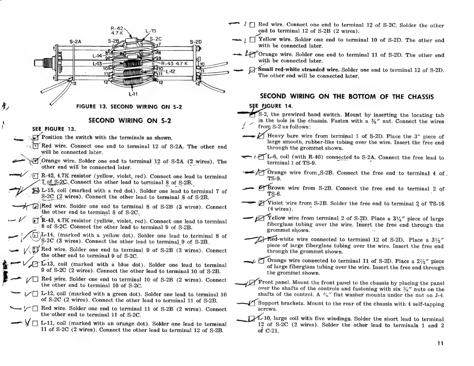
13.
SECOND
WIRING
ON
S-2
SECOND
WIRING
ON
S-2
SEE
FIGURE
13.
py
Position
the
switch
with
the
terminals
as
shown.
~\
[J
Red
wire.
Connect
one
end
to
terminal
12
of
S-2A.
The
other
end
will
be
connected
later.
-_
fry,
Orange
wire.
Solder
one
end
to
terminal
12
of
S-2A
(2
wires).
The
‘other
end
will
be
connected
later.
—
ey
R-
42,
4.7K
resistor
(yellow,
violet,
red).
Connect
one
lead
to
terminal
—
Toft
§-2C.
Connect
the
other
lead
to
terminal
8
of
S-2B.
“yee
L-15,
coil
(marked
with
a
red
dot).
Solder
one
lead
to
terminal
7
of
|
S-
2c.
(2
wires).
Connect
the
other
lead
to
terminal
8
of
S-2B.
Fa)
Rea
wire.
Solder
one
end
to
terminal
8
of
S-2B
(3
wires).
Connect
the
other
end
to
terminal
8
of
S-2C,
—
YY
oT
‘R-
43,
4.7K
resistor
(yelldw,
violet,
red).
Connect
one
lead
to
terminal
“8 of
S-2C.
Connect
the
other
lead
to
terminal
9
of
S-2B.
—
1
Ayes
(marked
with
a
yellow
dot).
Solder
one
lead
to
terminal
8
of
S
2C
(3
wires).
Connect
the
other
lead
to
terminal
_
9
of
S-2B..
res
Vil
/
Red
wire.
Solder
one
end
to
terminal
9
of
S-
2B
(3
wires).
Connect
the
other
end
to
terminal
9
of
S-2C.
—
Vy
1-13,
coil
(marked
with
a
blue
dot).
Solder
one
lead
to
terminal
9
of
S-2C
(2
wires).
Connect
the
other
lead
to
terminal
10
of
S-2B.
—_
yo
Red
wire.
Solder
one
end
to
terminal
10
of
S-2B
(2
wires).
Connect
the
other
end
to
terminal
10
of
S-2C.
“——
1/{]
L-12,
coil
(marked
with
a
green
dot).
Solder
one
lead
to
terminal
10
of
§-2C
(2
wires).
Connect
the
other
lead
to
terminal
11
of
$-2B.
“—
1
[[]
Red
wire.
Solder
one
end
to
terminal
11
of
S-2B
(2
wires).
Connect
the‘other
end
to
terminal
11
of
S-2C.
—
Vo
L-11,
coil
(marked
with
an
orange
dot).
Solder
one
lead
to
terminal
11
of
S-2C
(2
wires).
Connect
the
other
lead
to
terminal
12
of
$-2B.
~~
?/
[]
Red
wire.
Connect
one
end
to
terminal
12
of
S-2C,
Solder
the
other
end
to
terminal
12
of
S-2B
(2
wires).
——~
;
[]
Yellow
wire.
Solder
one
end
to
terminal
10
of
S-2D.
The
other
end
with
be
connected
later.
—
Leforange
wire.
Solder
one
end
to
terminal
11
of
S-2D.
The
other
end
with
be
connected
later.
sitet
Small
red-white
stranded
wire.
Solder
one
end
to
terminal
12
of
S-2D.
The
other
end
will
be
connected
later.
SECOND
WIRING
ON
THE
BOTTOM
OF
THE
CHASSIS
SEE
FIGURE
14.
8-2,
the
prewired
band
switch.
Mount
by
inserting
the
locating
tab
.
in
the
hole
in
the
chassis.
Fasten
with
a
34”
nut.
Connect
the
wires
io
See
of
from
S-2
as
follows:
—e
Heavy
bare
wire
from
terminal
1
of
S-2D.
Place
the
3”
piece
of
large
smooth,
rubber-like
tubing
over
the
wire.
Insert
the
free
end
through
the
grommet
shown.
—
LPT
L-
6,
coil
(with
R-40)
connected
to
S-
2A.
Connect
the
free
lead
to
terminal
1
of
TS-9.
<a
JT
Orange
wire
from
,S-2B.
Connect
the
free
end
to
terminal
4
of.
TS-9.
—
ex
Brown
wire
from
S-2B.
Connect
the
free
end
to
terminal
2
of
TS-6.
—
Violet
wire
from
S-2B.
Solder
the
free
end
to
terminal
2
of
TS-16
(4
wires).
—
[Yellow
wire
from
terminal,
2
of
S-
2D.
Place
a
314”
piece
of
large
fiberglass
tubing
over
the
wire.
lngent:
the
free
end
through
the
grommet
shown.
:
_—",
ed-white
wire
connected
to
terminal
12
of
S-2D,
Place
a
314”
piece
of
large
fiberglass
tubing
over
the
wire.
Insert
the
free
end
through
the
grommet
shown.
—y
£7
Orange
wire
connected
to
terminal
11
of
S-2D.
Place
a
214”
piece
of
large
fiberglass
tubing
over
the
wire.
Insert
the
free
end
through:
the
grommet
shown.
SA
Front
panel.
Mount
the
front
panel
to
the
chassis
by
placing
the
panel
over
the
shafts
of
the
controls
and
fastening
with
six
34”
nuts
on
the
shafts
of
the
control.
A
%4”
flat
washer
mounts
under
the
nut
on
J-4.
——7
Support
brackets.
Mount
to
the
rear
of
the
chassis
with
4
self-tapping
screws.
-10,
large
coil
with
five
windings.
Solder
the
short
lead
to
terminal
12
of
8-2C
(2
wires).
Solder
the
other
lead
to
terminals
1
and
2
of
C-21,
1

FIGURE
15.
CABLE
PREPARATION
UNRAVEL
SHIELD
WIRES,
TWIST
TOGETHER,
AND
COAT
TIP
WITH
SOLDER.
COAT
INNER
CONDUCTOR
SEE
FiGURE
14.
TIP
WITH
SOLDER.
L-24,
the
small
parasitic
suppressor.
Note
that
there
are
two
large
Sy
and
one
small
resistor
wrapped
with
several
turns
of
wire.
These
are
the
parasitic
suppressors.
The
small
one,
wound
on
a
15
watt
resistor,
ig
L-24.
Solder
one
lead
to
pin
7
of
V-3.
Solder
the
other
lead
to
the
ead
from
L-10.
—
C-19,
.005
pf
disc
capacitor.
Solder
one
lead
to
ground
lug
A
of
V-3,
B
wires)
Connect
the
other
lead,
to
erat
1
of
TS-10.
ORAL
Wind
~~
fe
resistor
;
black,
.
Connect
one
end
to
pin
2
of
V-
3.
Connect
the
other
lead
to
terminal
1
of
TS-10.
nen
a
Red
wire
from
S-2A.
Solder
the
free
end
to
terminal
2
of
C-16
wires).
~
dove
wire
from
S-2A.
Connect
the
free
end
to
terminal
2
of
TS-10.
C-17,
.005
pf
disc
capacitor.
Solder
one
lead
to
pin
?
of
V-3
(2
wires).
Solder
the
other
lead
to
terminal
2
of
TS-10
(2
wires).
R-8,
5600,
5%
resistor
(green,
blue,
brown,
gold).
Solder
one
lead
to
terminal
1
of
TS-10
(4
wires).
Solder
the
other
lead
to
terminal
3
of
TS0
apie
we
C-53,
.005
jf,
disc
capacitor.
Solder
one
lead
to
pin
9,of
V-4
(3
wires).
Connect
the
other
end
to
ground
lug
A
of
V-4.
t
4”
piece
of
shielded
cable.
Prepare
the
ends
as
shown
in
Figure
15.
Solder
the
inner
conductor
of
one
end
tg.pin
2,of
V-4.
Solder
the
shield
wire
to
ground
lug
A
of
_V-4
(2
wires).
Connect
th
the
inner
con-
ductor
of
the
other
end
to
terminal
2
of
TS-11.
Connect
the
shield
Oy
wire
to
terminal
1
of
TS-11.
Se
—
ate.
12
—
Ff
114,”
piece
of
the
small
bare
wire.
Insert
the
wire
through
pins
5,
4
and
3
of
V-4
and
solder
to
ground
lug
B
of
V-4.
Solder
pins
3,
4
and
5.
R-25,
1.5K
resistor
(brown,
green,
red).
Connect
one
lead
to
pin
&
ea
of
V-4,
Connect
the
other
lead
to
terminal
3
of
R-23.
—
ine
cord.
Insert
the
line
cord
through
the
grommet
shown.
Tie
a
knot
in
the
cord
4”
from
the
end.
Split
the
two
wires
back
1”
from
the
end.
Solder
either
one
of
the
wires
to
terminal
1
of
the
fuse
Ider.
Solder
the
other
wire
to
terminal_1,
of
TS-4
(3
wires).
—
C-28,
.001
pf
disc
capacitor.
Connect
one
lead
to
pin
3
of
V-8.
Connect
the-other
lead
to
the
solder
lug
mounted
at
the
end
of
thé
socket.
—
C-30,
.005
»f
disc
capacitor.
Position
the
capacitor
in
the
center
of
tube
socket
V-8
as
shown.
Insert
one
lead
through
pin
2
of
V-8 and
solder
lug
(2
wires).
Solder
pin
2
of
V-
ires).
Solder
the
other
lead
to
pin
6
of
V-
V-3,
C
25,
005
pf
disc
capacitor.
"Position
the
‘capacitor
i
in
the
center
of
tube
socket
V-7
as
shown.
Solder
one
lead
to
pin
6_of
V-7.
Insert
the
other
lead
through
pin
2
of
Y-7
and
solder
to
the
solder
lug.
7:
C-27,
.001
yf
disc
capacitor.
Solder.
one
lead
to
pin
3
of
ve
af
(2
wires).
Solder
the
other
lead
to
pin
2
of,
V-7
(5
wires).
ie
ol
FT
‘Blue
wire.
Solder
one
end
to
pin
1
of
V-7
end
to
terminal
4
of
TS-10
(3%
Wires).
R-12,
22K
2
watt
resistor
(red,
red,
orange).
Connect
one
lead
to
terminal
1
1
of
TS-3.
Connect
the
other
lead
to
terminal
3
of
TS-3.
’
Violet
wire.
a.
Solder
one
end
to
terminal
3
of
TS-3
(4
wires).
Solder
the
other
end
to
terminal
8
of
S-4.
ob
Br
C]
L-7,
coil
(marked
with,
a
gray
dot)
1
ea
R-41,
resistor
(yeltow,
,
Vv
Solder
R-41
across
L-7
in
the
same
manner
R-40.
was
nted
to
L-6
(See
Figure
-
12).
‘Solder
one
lead
from
L-
7
to
terminal
«
4
of
S-2A
(2
wires).
Connect
the
other
lead
to
terminal
1
of
.TS-9.
:
—T
f-8,
black
dot
coil.
Solder
one
lead
to
terminal
5
of
S-2A.
Connect
the
other
lead
to
terminal
1
of
TS-9.
we
[7].
Y
9,
white
dot
coil.
Solder
one
lead
to
terminal
6
of
S-2A.
Connect
the
other
lead
to
terminal
1
of
TS-9.
Ae
wires).
Solder
the
other
Sonn
>
/
—=
C-22,
330
nyf
mica
capacitor.
Solder
<
one
lead
to
terminal
3
of
TS-8.
nnect
the
other
lead
to
terminal
Jof
S-2
2C._
ta
tie
—
Green
wire.
Solder
one
end
to
terminal
1
of
S-2C
(3
wires).
Place
i
a
41/4,”
piece
of
large
tubing
over
thé
wire.
Insert
the
other
end
fough
the
grommet
shown.
—-
TS-14,
3-terminal
strip.
Mount
TS-14
in
the
remaining
mounting
hole
-7.
Use
a
4-40
x
14”
screw,
lockwasher
and
nut.
of
—_—
AY
Tubing
covered
yellow
wire
from
J-7.
Solder
the
free
end
to
terminal
Sat
82D.
oon
Zi
R-17,
the
4.7K
resistor
from
J-7.
Connect
the
free
lead
to
terminal
1
of
TS-14.
Pax
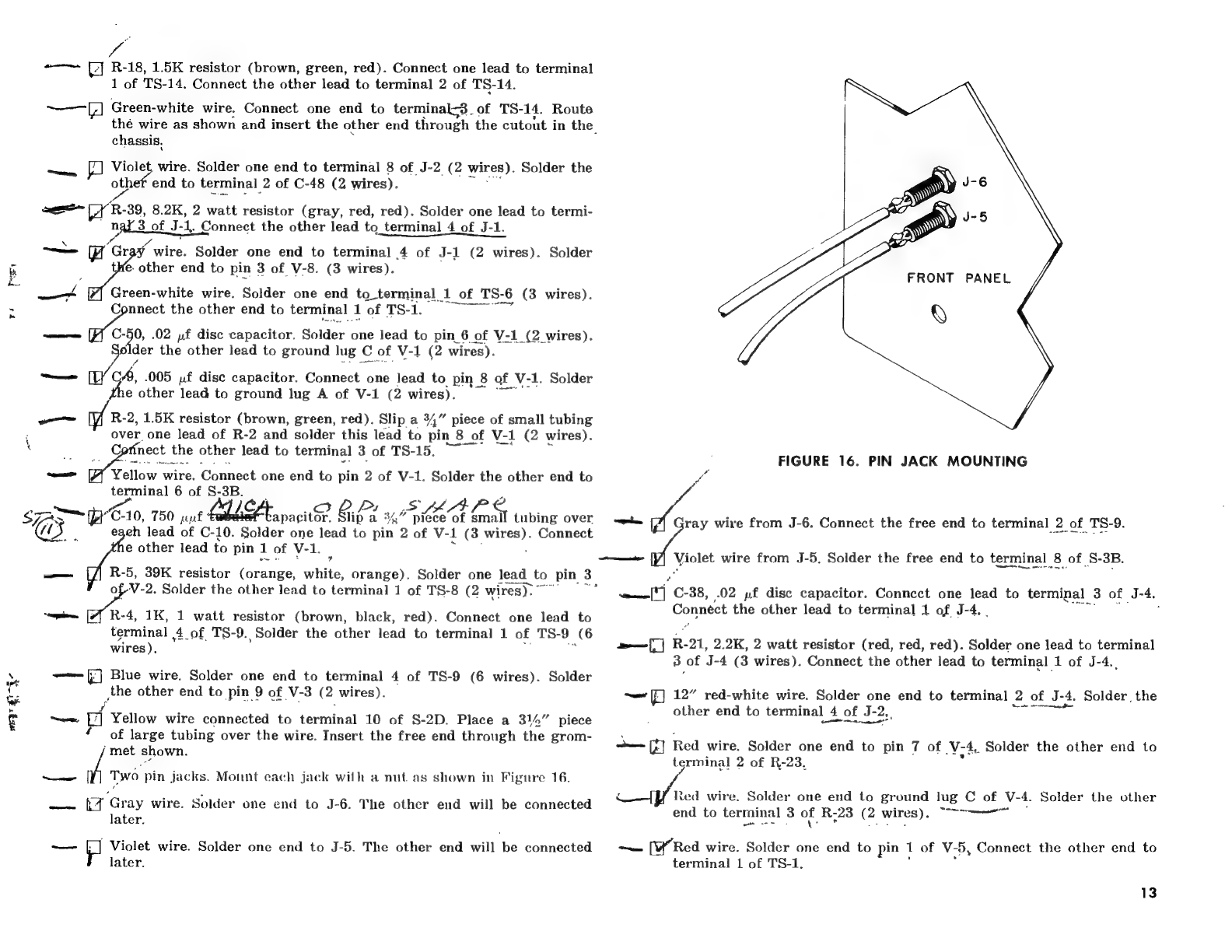
wEyt
:
a
sas
“EXO,
750
jf
ae
—
la
R-18,
1.5K
resistor
(brown,
green,
red).
Connect
one
lead
to
terminal
1
of
TS-14.
Connect
the
other
lead
to
terminal
2
of
TS-14.
~———[;]
Green-white
wire.
Connect
one
end
to
terminal;3.
of
TS-
14.
Route
thé
wire
as
shown
and
insert
the
other
end
through
the
cutout
in
the
chassis,
siecads
|]
Violet,
wire.
Solder
one
end
to
terminal
8
of
J-2
(2
wires).
Solder
the
oo
end
to
terminal
2
of
C-48
(2
wires).
see
TY
R-
-39,
8.2K,
2
watt
resistor
(gray,
red,
red).
Solder
one
lead
to
termi-
nal
3
of
J-
1.
Connect
the
other
lead
to_terminal
4
of
J-1.
—
iw
‘Gray
wire.
Solder
one
end
to
terminal
4
of
J-1
(2
wires).
Solder
tHe.
other
end
to
pin
3
of
V-8.
(3
wires).
7]
Green-white
wire.
Solder
one
end
to_terminal
1
of
TS-
6
(3
wires).
vem
the
other
end
to
terminal
1
of
TS-1,0
—
0,
.02
uf
disc
capacitor.
Solder
one
lead
to
pin
6
of
V-1
(2
wires).
older
the
other
lead
to
ground
lug
c
of
V-1
(2
wires).
—
oy
005
yf
disc
capacitor.
Connect
one
lead
to
pin
8
of
V-1.
Solder
e
other
lead
to
ground
lug
A
of
V-1
(2
wires).
na
R-2,
1.5K
resistor
(brown,
green,
red).
Slip
a
34”
piece
of
small
tubing
over
one
lead
of
R-2
and
solder
this
lead
to
pin
8
¢
of
V-1
(2
wires).
;
C
fnect
the
other
lead
to
terminal
3
of
TS-15.
—
Yellow
wire.
Connect
one
end
to
pin
2
of
V-1.
Solder
the
other
end
to
terminal
6
of
S-3B.
:
s
4
_S
apaeitor
Gie%
5
3”
piece
of
small
tubing
over
egeh
lead
of
C-10.
Solder
one
lead
to
pin
2
of
V-
1
(3
ware
Connect
e
other
lead
to
pin
1
of
V-1.
—
a
5,
39K
resistor
fopange
white,
orange).
Solder
one
lead
to
pin
3
LV-
2.
Solder
the
other
lead
to
terminal
1
of
TS-8
(2
wires).
”
copie.
[77
R-4,
1K,
1
watt
resistor
(brown,
black,
red).
Connect
one
lead
to
terminal
4.of
TS-9.
,
Solder
the
other
lead
to
terminal
1
of
TS-
a
(6
wires).
~—~-
(/]
Blue
wire.
Solder
one
end
to
terminal
4
of
TS-9
(6
wires).
Solder
the
other
end
to
pin
9
of
V-
3
(2
wires).
—
of
Yellow
wire
connected
to
terminal
10
of
S-2D.
Place
a
314”
piece
‘of
large
tubing
over
the
wire.
Insert
the
free
end
through
the
grom-
‘met
shown.
emer
Two
pin
jacks.
Mount
each
jack
wilh
a
nut.
as
shown
in
Fignre
16.
pane
tq
Gray
wire.
Solder
one
end
to
J-6.
The
other
end
will
be
connected
later.
|
Violet
wire.
Solder
one
end
to
J-5.
The
other
end
will
be
connected
later.
~——a
FRONT
PANEL
Q
FIGURE
16.
PIN
JACK
MOUNTING
~*~
[7]
Gray
wire
from
J-6.
Connect
the
free
end
to
terminal
2
of
TS-9.
of
om
wire
from
J-5,
Solder
the
free
end
to
terminal
8
of
S-3B,
eee)
C-38,
.02
pf
disc
capacitor.
Conncct
one
lead
to
terminal
3
of
J-
4.
Connect
the
other
lead
to
terminal
1
of
J-4.
.
a—i|
R-21,
2.2K,
2
watt
resistor
(red,
red,
red).
Solder
one
lead
to
terminal
3
of
J-4
(3
wires).
Connect
the
other
lead
to
terminal
1
of
J-4..
~~
12”
red-white
wire.
Solder
one
end
to
terminal
2
of
J-
‘A.
Solder,
the
other
end
to
terminal
4
of
J-
2.
See
PS
Red
wire.
Solder
one
end
to
pin
7
of
ve
4,
Solder
the
other
end
to
terminal
2
of
R-23,
Red
wire.
Solder
one
end
to
ground
lug
C
of
V-4.
Solder
the
other
end
to
terminal
3
of
R-23
(2
wires).
ea
~~
[W’Red
wire.
Solder
one
end
to
pin
1
1
of
V-5,
Connect
the
other
end
to
terminal
1
of
TS-1.
13
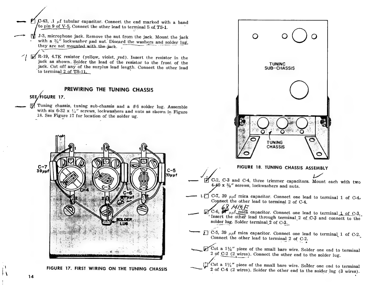
=
-43,
.1
»f
tubular
capacitor.
Connect
the
end
marked
with
a
ban
to
pin
9
of
V-5,
Connect
the
other
lead
to
terminal
5,
of
TS-1.
:
A
Se
aa
nd
J-3,
microphone
jack.
Remove
the
nut
from
the
jack.
Mount
the
jack
O
C)
O
-
with
a
3%”
lockwasher
and
nut.
Discard
the
washers
and
solder
lug,
they
are not
mounted
with
the-jack.
~~~
~~
x
ay
es
4.7K
resistor
(yellow,
violet,
wed).
Insert
the
resistor
in
the
jack
as
shown..
Solder
the
lead
of
the
resistor
to
the
front
of
the
TUNING
jack.
Cut
off
any
of
the
surplus
lead
length.
Connect
the
other
lead
SUB-CHASSIS
‘to
terminal
2
of
TS-11,
;
PREWIRING
THE
TUNING
CHASSIS
SEE
FIGURE
17.
eee
Tuning
chassis,
tuning
sub-chassis
and
a
#6
solder
lug.
Assemble
with
six
6-32
x
1,”
screws,
lockwashers
and
nuts
as
shown
in
Figure
18.
See
Figure
17
for
location
of
the
solder
ug.
TUNING
CHASSIS
FIGURE
18.
TUNING
CHASSIS
ASSEMBLY
ae
C.2,
C-3
and
C-4,
three
trimmer
capacitors.
Mount
each
with
two
4-40
x
34”
screws,
lockwashers
and
nuts.
—_—
LE]
C-7,
39
uf
mica
capacitor.
Connect
one
lead
to
terminal
1
of
C-4,
Connect
the
other
lead
to
terminal
2
of
C-4.
WA
6X
MME
——
(iC,
upf
mica
capacitor.
Connect
one
lead
to
terminal
1
of
C-3..
‘Insert
the
other
lead
through
terminal
2
of
C-3
and
connect
to
the
solder
lug.
Solder
terminal_2
of
C-3..
=>
C5,
39
y»yf
mica
capacitor.
Connect
one
lead
to
terminal,
1
of
C-2.
Connect
the
other
lead
to
terminal
2
of
C-2.
aaa
oar
et
Cut
a
144”
piece
of
the
small
bare
wire.
Solder
one
end
to
terminal
2
of
£2
(2
wires).
Connect
the
other
end
to
the
solder
lug.
vA
;
Gl
Cut
a
114”
piece
of
the
small
bare
wire.
Solder
one
end
to
terminal
FIGURE
17.
FIRST
WIRING
ON
THE
TUNING
CHASSIS
—
2
of
C-4
(2
wires).
Solder
the
other
end
to
the
solder
lug
(3
wires).
\
:
14

§
—
—t
ce
~~
oe
«a
=
(J):
1
FIGURE
19.
SECOND
WIRING
ON
THE
TUNING
CHASSIS
SECOND
WIRING
ON
THE
TUNING
CHASSIS
t
SEE/
FIGURE
19.
all
grommet.
Insert
in
the
hole
shown.
C-1,
3-section
variable
capacitor
(part
#286055).
Insert
the
shaft
of
the
capacitor
through
the
hole
in
the
tuning
sub-chassis.
Mount
with
three
6-32
x
4,”
screws
and
lockwashers.
See
Figure
21
for
a
top
view
of
C-1.
:
et
eee
re
pse
CAP,
FL2
Cork
C60
4-19}
D
CON
N2aTr
FV
CEHKDP
Of
MARK
EL
VIITP
A
Yeblbow
batTr
Te
Terypy
has
1
ef
LD.
On
ATI
Oe
>
ees.
we
pa
lowing
coils
as
shown
in
Figure
20.
ae
th
}
L-1,
orange
dot
coil.
~
a
-3/Yellow
dot
coil.
WY/7A
Ga.
A
a
om,
Obl
Atria
eto
L-3,
red
dot
coll.
WW/7A
(pw
(RE3
>
————
:
@
yf
Orange
wire.
Solder
one
end
to
terminal
1
of
L-3:
Insert
the
other
end
through
the
grommet
shown,
it
will
be
connected
later.
°
(2
W/RES)
m=1h)
sg
an,
Ae
wire.
Solder
one
end
to
terminal
1
of
L-2.
Insert
the
other
end
through
the
grommet
shown,
it
will
be
connected
later.
ae
ee
reen
wire.
Solder
one
end
to
terminal
1
of
L-1.
Insert.
the
other
end
through
the
grommet
shown,
it
will
be
connected
later.
be
connected
later.
4
;
be
connected
later.
be
co
Oorhes
mnected
later.
LOCKING
SPRING
SLUG
TUNED
COIL
Ch,
ol
7
—
aan
wireSolder
one
end
to
terminal
2
of
L-1.
The
other
end
will
(qwires?
lue
wire.
Solder
one
end
to
terminal
2
of
_L-2.
The
other
end
will
@
VU
LA
Es>
,
Green
wire.
Solder
one
end
to
terminal
2
of
L-3.
The
other
end
will
LOCATING
PIN
FIGURE
20.
COIL
MOUNTING
Tt
RAG
VAC
Kaa?
LEAS
S$
Kat
7~
C-GO
wy
Oe
ye
ees
aa
ee

“+
Siew
bi
bt
Tp
>
a
Tree
min
aoe
y
SHES:
%.
€0nKNe
ap
7/12
i
r
FE
PAPE
KY
Ce
Riv
a
a
C7tes
y-e
fs
tes
eigen
de
Man
bps
Ve.
So
.
Be)
93
protective
SY
Gam
unt
to
the
lee
en
ith
ape
Aah
Cap
(as
FEW
Plastic
plate.
Remove
Thy
two
4-40
x
1,”
screws,
lockwashers
and
nuts.
Ay
===]
Dial,
threaded
collar,
setscrew,
14,”
lockwasher
<q
shown
in
Figure
22.
eu
~———{3]
Dial
assembly.
Place
over
the
shaft
of
C-1,
the
variable
capacitor
sy
mounted
on
the
tuning
chassis.
~
QD:
Sacco
TS-15
mounting
hardware.
Remove
the
hardware
mounting
TS-15
to
=
A
the
chassis.
One
of
the
screws
used
in
the
next
step
will
remount
TS-15
i
=
to,
the
chassis.
ah
ee
fd
Position
the
tuning
chassis
on
the
main
chassis
with
the.
shaft
of
\
C-1
through
the
hole
in
the
plastic
plate.
Mount
the
tuning
chassis
by
with
four
self-tapping
screws
(one
re-mounts
TS-15).
Insert
the
wires
f
from
the
tuning
chassis
through
the
grommet.
z
GY
Close
the
blades
of
C-1
all
the
way.
Fasten
the
dial
scale
to
the
shaft
LY
la
|
of
C-1
with
the
setscrew.
With
the
blades
closed
all
the
way
the
=f
s
hairline
on
the
window
should
be
on
the
white
line
on
the
scale.
~wJ
IF
TS-13,
2-terminal
strip.
Mount
with
a
6-32
x
'4”
screw,
lockwasher
a
and
nut.
wo)
\
f
eS
Orange
wire
from
the
grommet
in
the
tuning
chassis.
Solder
the
free
end
to
terminal
4
of
C-1.
worl
Yellow
wire
from
the
grommet
in
the
tuning
chassis.
Solder
the
free
end
to
terminal
5
of
C-1.
Green
wire
from
the
grommet
in
the
tuning
chassis.
Solder
the
free
end
to
terminal
6
of
C-1.
—=([F}
Cut
three
1”
pieces
of
the
small
bare
wire.
Connect
these
wires
as
follows:
ode
woe
FY
Bare
wire.
Solder
one
end
to
terminal
1
of
C-1.
Solder
the
other
fid
to
terminal
1
of
C-4
(2
wires).
eee
are
wire.
Solder
one
end
to
terminal
2
of
C-1.
Solder
the
other
oad
to
terminal
1
of
C-3
(2
wires).
@=-({]’
Bare
wire.
Solder
one
end
to
terminal
3
of
C-1..Solder
the
other
“end
to
terminal
1
of
C-2
(2
wires).
Pilot
light
socket
and
bulb.
Insert
the
pilot
light
in
the
socket.
Mount
the
socket
to
the
tuning
chassis.
(s
porn:
The
pilot
light
leads
may
be
shortened
for
neater
connections.
sr
ae
&
=4
CUFASS
IS,
&
-~Az
SECO!
Sey
Lon
VAS
Hn
PO
7
t9)
wan
nyect
either
of
the
pilot
light
leads
to
terminal
2
of
ae
13.
Connect
%
other
lead
to
terminal
1
of
TS-13..
SS
5:
C-55,
.02
;f
disc
capacitor.
Solder
one
lead
to
terminal
1
of
TS-
13
(2
\
ay
wires).
Connect
the
other
lead
to
terminal
2
of
TS-13.
~T
Brown
wire.
Solder
one
lead
to
terminal
2
of
TS-13
(3
wires).
Insert
Us
the
other
end
through
the
grommet.
y“94
:
-
9)
ty
.
.
(al
=
|
ay
®
OFT
Obi
Gired
ro
FIRST
WIRING
ON
THE
TOP
i
ike
Re
S
and
nut.
Assemble
as
The,
eg!
ny
coil
w
nae
ss
@
we
of}
Tekh
2a
Awe
Z
of
L
3)
Ke
3°
he
Le
ees
Ke
gsp~
J
ee
cpoes
bi
ne
shield.
Fasten
the
top
shield
in
place
with
two
6-32
x
3/16”
screws
and
lockwashers.
Fasten
to
the
angle
clips.
jou
ety
ACS
—
ta}
L-20,
the
large
coil
and
four
#8
solder
lugs.
Bend
the
solder
lugs
ngs
sx
solder,
jn,
place
3s
Shows
|
in
Figure
23.
235
5
ol.
il
¢
core
by
bending
one
of
the
solder
lugs
on
ie
E26
over
the
coil
leads.
Solder
the
coil
to
the
solder
lugs.
‘ubing
covered
bare
wire
from
the
grommet
near
the
back
of
the
chassis.
Connect
the
free
end
to
solder
lug
+6
of
L-20.
—
a)
Pubing
covered
yellow
wire
from
the
large
grommet,
Solder
the
free
ae
to
solder
lug
#5
of
L-20.
—-
pe
bing
covered
orange
wire
from
the
large
grommet.
Solder
the
free
oad
to
solder
lug
#4
of
L-20.
—
mie
Tubing
covered
red-white
stranded
wire
from
the
large
grommet.
Solder
the
free
end
to
solder
lug
#3
of
L-20.
a)
Tubing
covered
heavy
bare
wire
from
the
large
grommet.
Solder
the
free
end
to
solder
lug
Rot
L-20,
Lee
Ben
Prat
En
Nb
;
7
ro
Oovuete
Faa
ives
ay
“—_
ret,
ah
A>
SETSCREW
Ore
NUT
I
THREADED
{
LOCKWASHER
COLLAR
FIGURE
22.
DIAL
SCALE
ASSEMBLY

Dpbey
EOE.
ae.
4z
SOLDER
s|65|3|
1
Lus:'{4)
rink
ai
hii
|
FIGURE
23.
L-20
PREPARATION
St
pr
te
—
Tubing
covered
green
wire
from
the
4eugm.gromm
en
o
terminal
1
of
TS-12.
|
Le
a
eal
PE
yo
Two
orange
wires.
Solder
one
end
of
each
wire
to
terminal
lof
TS-12.
S
(3
wifes).
Bend
the
ends
of
the
wires
around
the
,tube.
sockets
at
a
ht_o
OT
BE
CONNECTED
ANYWHERE,
but
will_be
used
to
neutralize
i===
[-f
Cut
an
11”
piece
of
the
large
bare
wire
and
two
pieces
of
the
large
Ce
z]
C-31,
.005
pf,
1000
volts
(marked
1KV)
disc
‘capacitor.
Connect
one
|
’
above
the
chassis.
The
free
ends
of
these
wires
WILL
e
»
Pelere.,
‘
tubing;
one
2”
and
one
4”.
Slide
the
two
pieces
over
the
large
bare
wire.
Form
the
wire
as
shown
in
Figure
24.
Solder
a
yellow
wire
to
[the
bare
wire
as
shown.
_
Solder
the
end
of
the
bare
wire
that
is
closest
to
the
yellow
wire
to
terminals
1
and
2
of
C-35.
Route
the
busbar
under
L-20
and
solder’
the
other
end
to
solder
lug
#6
of
L-20
(2
wires).
,
a
a
314”
piece
of
the
large
tubing
over
the
yellow
wire
connected
to
the
busbar.
Insert
the
free
end
through
the
grommet
shown.
,
ert
sin
et.
Connect
the
free
Spe
Tek®,
the—large—coil—with—three—windings.
Selderthe—longlead—to-
:
wires),
TAC
7AP.
Peek
COSC,
52
DER
BIF
ode
Ct
Bea
LE
fe
j
y
W//RE,
Sg
ee
SRY
20.
yrs
ak
=
e’
lead
to
the
terminal
of
L-18.
Solder
the
other
lead
to
L-19
"e
ha
é
: ,
show
pre
fe
the
output
tubes.
Cut
off
the
bare
portion
of
the
wires
at
the
free
ends.
eT
~
%
Grecia
ta
any
:
TE:
The
two
parasitic
chokes
are
identical.
=
"
Res
:
a
‘
iy
1
—,
L-16,
parasitic
choke
(coil
wound
on
a
2
watt
resistor).
Cut
one
lead
Nga
1
So
it
is
14”
long.
Solder
this
lead
to
a
plate
clip
as
shown
in
Figure
25.
tr
fe
os
Cut
the
other
lead
so
it
is
1”
long.
Connect
this
lead
to
the
terminal
uc
of
L,18.
The
plate
clip
will
be
connected
later.
Se
<
OO,
pias
L-17,
the
other
parasitic
choke.
Cut
one
lead
so
it
is
1”
long.
Solder
re
‘
this
lead
to
a
plate
clip.
Cut
the
other
lead
so
it
is
114”
long.
Solder
ve
re.
i
this
lead
to
the
terminal
of
L-18
(3
wires).
The
plate
clip
will
be
Aw
connected
later.
w
HEAVY
BARE
WIRE
YELLOW
WIRE
FIGURE
24,
BUSBAR
ASSEMBLY
a
eter.
Remove
the
jumper
wire
from
the
two
terminals.
Mount
the
meter
to
the
panel
with
four
4-40
nuts
and
split
washers.
The
hard-
ware
used
to
mount
the
meter
is
packed
in
the
box
with
the
meter.
Mount
a
#10
solder
lug
to
each
meter
terminal
with
a
10-32
flat
washer
and
nut.
PTR”
PARASITIC
CHOKE
L-16
AND
17
(G
a
FIGURE
25.
CHOKE
PREPARATION
Ve
bref
yrsrrty
Ys
R24
Suen
Ae
DIVAS
rat
Rt
RA
A
ord
2D
17

LN
G
=
~
wf
StREw
EA
Lee
washpty.
HO
She
Down
Leys
cut
a
34”
piece
of
the
small,
bare
wire.
Connect
one
end
to
terminal
1
of
S-4.
Connect
the
other
end
to
ferminal
2
of
8-4.
Cut
a
114”
piece
of
the
small
bare
wire.
Place
a
34”
piece
of
small
tubing
over
the
wire.
Solder
one
end
to
terminal
2
of
S-4
(2
wires).
older
the
other
end
to
terminal
4
of
S-4.
©
&.
Orange
wire
from
the
cutout
in
the
chassis.
Solder
the
free
end
to
terminal
1
of
S-4
(2
wires).
af
White
wire
from
the
cutout
in
the
chassis.
Solder
the
free
end
to
tertninal
3
of
S-4.
Green
wire
from
terminal
11
of
S-4.
Genneet
the
free
end
to
terminal
of
the
meter
f
Yellow
wire
from
terminal
10
of
S-4.
Connect
the
free
end
to
terminal
of
R-16
fd
C-34,
.005
pf
disc
capacitor.
Solder
one
lead
to
terminal
2
of
R-16
(2
wires).
Connect
the
other
lead
to
terminal
1
of
R-
-16.
¢
Fl
Red-white
wire
from
the
cutout
in
the
chassis.
Solder
the
free
end
to
terminal
1
of
R-16
(2
wires).
EA
Green-
white
wire
from
the
cutout
in
the
chassis.
Solder
the
free
end
te
‘terminal
3
of
R-16.
“Yellow
wire.
Solder
one
end
to
terminal
5
of
S-4.
_Gonnect
the
other
énd
to
terminal
1
of
the
meter.
—
C-37,
.005
yf
disc
capacitor.
Solder
one
lead
to
terminal
1
of
the
meter
(2
wires).
Solder
the
other
lead
to
terminal
2
of
the
meter
(2
wires).
2
ET
ee
EET
eg
FINAL
WIRING
ON
THE
CHASSIS
EE
FIGURE
26
Greén
wire
from
the
grommet
near
S-3.
Solder
the
free
end
to
termi-
£5-3B.
Blue
wire
from
the
grommet
near
8-3.
Solder
the
free
end
to
termi-
nal
4
of
S-
3B.
[7]
Violet
wire
foi
the
grommet
near
S-3.
Solder
the
free
end
to
termi-
nat
5
of
8-3B.
Brown
wire
from
the
grommet
near
S-3.
Connect
the
free
end
to
tenmunat
1
of
TS-7.
—-
eres
wire.
Solder
one
end
to
terminal
1
of
TS-7
(4
wires).
Connect
the
other
end
to
terminal
2
of
J-2.
18
,
d
NOTE:
There
are
three
diodes
used
in
the
transmitter.
CR-1
and
CR-2,
of
aa
Red
wire.
Solder
one
end
to
terminal
6
of
S-1B.
Solder
the
other
end
to
terminal
1
of
S-1C
(2
wires).
E42”
red-white
wire.
Solder
one
end
to
terminal
5
of
S-1B.
Solder
the
other
end
to
terminal
6
of
J-2.
“White
wire.
Solder
one
end
to
terminal
5
of
S-1A.
Solder
the
other
end
to
terminal
2
of
TS-6
(3
wires).
Se
Ne
AY
Brown-
white
wire.
Solder
one
end
to
terminal
6
of
S-1A.
Solder
the
other
end
to
terminal
2
of
J-1.
Violet
wire.
Solder
one
end
to
terminal
7
of
J-1.
Solder
the
other
ne
to
terminal
2
of
T'S-8
(3
wires).
..
“Blue
wire.
Solder
one
end
to
terminal
5
of
J-2.
Solder
the
other
end
o
terminal
|
2
of
TS-5
(3
wires).
Green
wire.
Connect
one
end
to
terminal
2
of
J-
2,
Solder
the
other
end
to
pin
7
of
V-8
(
2
wires).
tal
Bide
wire.
Solder
one
end
to
terminal
2
of
J-2
(3
wires).
Solder
the
other
end
to
pin
5
of
V-2
(2
wires).
ase
és,
-001
yf
disc
capacitor.
Solder
one
lead
to
pin
8
of
V-2.
Solder
the
othér
lead
to
terminal
2
of
TS-9
(2
wires).
‘mn
B
3/100K
resistor
(brown,
black,
yellow).
Solder
one
lead
to
pin
9
-2.
Solder
the
other
lead
to
terminal
3
of
TS-9.
ya
C-11,
750
pf
mica
capacitor.
Connect
one
lead
to
pin
1
of
V-1.
Solder
zene
other
lead
to
ground
lug
B
of
V-1.
(2
wires).
\
NOTE:
Coils
L-4
and
L-5
are
identical.
v
("]
L-5.
Solder
one
lead
to
pin
1
of
V-1
(3
wires).
Connect
the
other
lead
to
terminal
1
of
TS-157""~""”
Cicer
wire.
Solder
one
end
to
terminal
1
of
J-4
(4
wires).
Solder
the
other
end
to
terminal
1
of
TS-15
(2
wires).
Tah
L-4.
Solder
one
lead
to
_pin
7
of
V-
1
(2
wines):
Connect
the
other
lead
to
oe
3
of
TS-
15."
iv
Ly
c
59;
"005
pf
disc
capacitor.
Solder
lead
end
to
terminal
3
of
TS-15
ae
wires).
Solder
the
other
lead
to
terminal
2
of
TS-15.
C-
en
iad
36,
005
pf
disc
capacitor.
Solder
one
lead
to
terminal
2
of
TS-14.
TN
et
(2
wires).
Connect
the
other
lead
to
terminal
3
of
TS-
14,
the
rectifiers
are
identical.
CR-3
the
meter
rectifier
is
different
in
shape
than
CR-1
and
CR-2.
The
marked
ends
of
the
diodes
may
be
marked
with
a
band,
a
dot,
several
colored
bands
or
have
the
end
colored
red.
When
wiring
the
diodes
be
sure
to
position
the
marked
end
exactly
as
instructed.
Lf
“CR-3,
meter
rectifier.
Solder
the
marked
end
to
terminal
1
of
TS-14
(3
wires).
Solder
the
other
lead
to
terminal
3
of
TS-14
(3
wires).
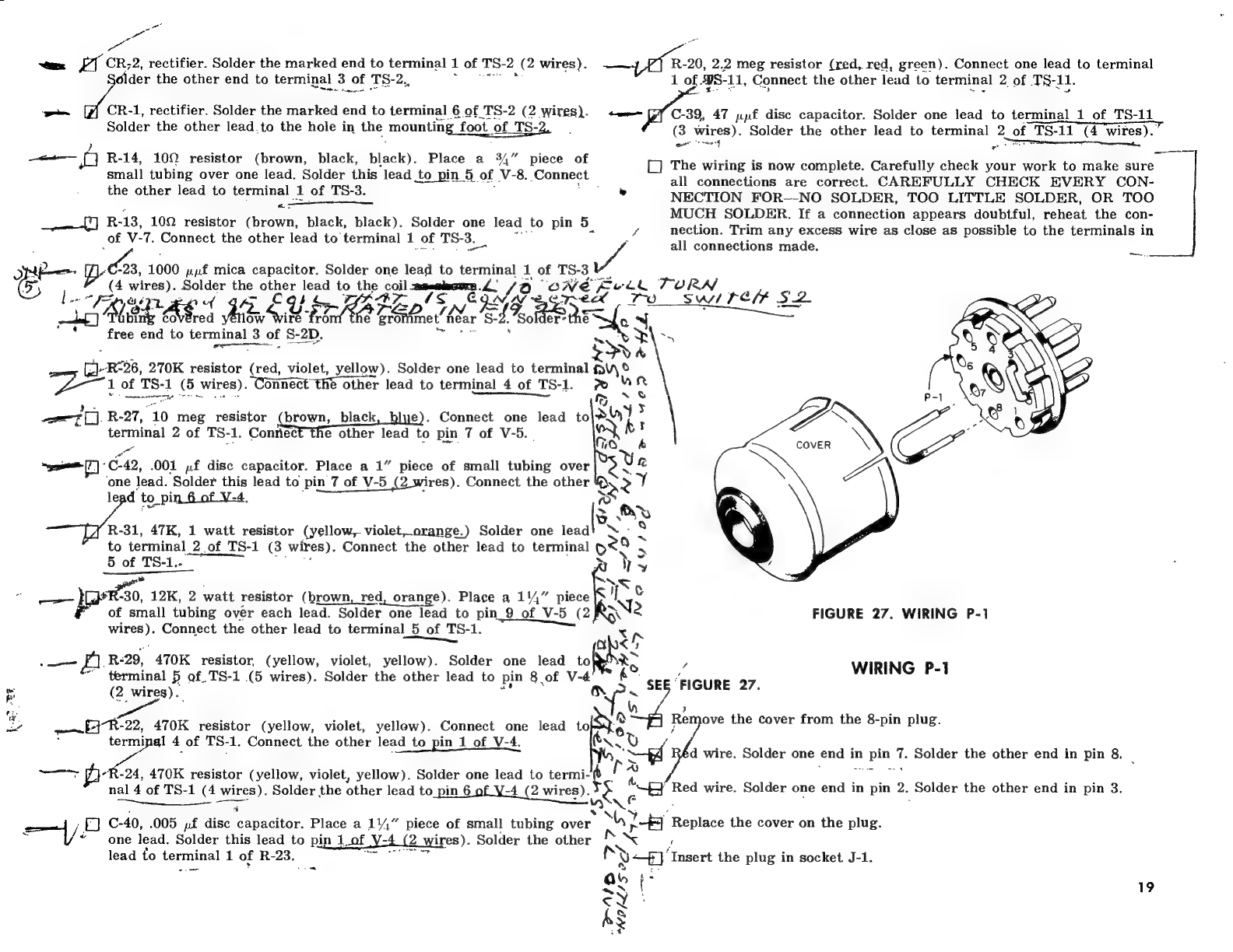
“
on
oe
FI
CR;
2,
rectifier.
Solder
the
marked
end
to
terminal
1
of
TS-
2
ae
wires).
eR,
2.2
meg
resistor
(red,
red,
green).
Connect
one
lead
to
terminal
itn
the
other
end
to
terminal
3
of
TS-2,,
.
1
of
YS-11,
Connect
the
other
lead
to
terminal
2
of
T§-11.
—
CR-1,
rectifier.
Solder
the
marked
end
to
terminal
6
of
TS-2
(2
wires).
+-e=
G7°C-39,
47
ppf
disc
capacitor.
Solder
one
lead
to
terminal
1
of
TS-11
Solder
the
other
lead.to
the
hole
in
the
mounting
foot.
of
TS-
:
(3
wires).
Solder
the
other
lead
to
terminal
2
of
TS-11
(4
wires).
)
ee
saad
2s
SET
renee,
os
on
R-14,
100
resistor
(brown,
black,
black).
Place
a
34”
piece
of
The
wierd
g
is
now
complete.
Carefully
check
your
work
to
make
sure
small
tubing
over
one
lead.
Solder
this
lead
to
pin
5.
of
N-8.
Connect
©
0
all
connections
are
correct.
CAREFULLY
CHECK
EVERY
CON-
the
other
lead
to
terminal
1
of
TS-3.
»
NECTION
FOR—-NO
SOLDER,
TOO
LITTLE
SOLDER,
OR
TOO
“at
R-
13,
100
#eeintod
“Chrown,
‘black,
Black):
-Soldee
nie
lead
‘to
pin
5
MUCH
SOLDER.
If
a
connection
appears
doubtful,
reheat
the
con-
y
nection.
Trim
any
excess
wire
as
close
as
possible
to
the
terminals
in
of
V-7.
Connect
the
other
lead
to
terminal
1
of
TS-3.
eA
all
aonnesiiond
wade:
-
eT.
Be
on.
1000
ppf
mica
capacitor.
Solder
one
lead
to
rag
1
of
TS-3
roe
ee
wires).
Solder
the
£9
lead
to
the
SIRES
“oNMve
ye
RA
;
leg
3
y
Sw
PE
$2
:
“Met
aS
ASS
Me
Mane
ire
Ui
RAPE
ae
fet!
Kar
a4
Bolte
SJ
HH
free
end
to
terminal
3
of
S-2D.
=
a
&
ce
R226,
270K
resistor
Gea
violet,
yellow).
Solder
one
lead
to
terminal
ae
ca
of
TS-1
(5
wires).
Connect
the
other
lead
to
terminal
4
of
TS-1.
x
8
nr
S
ener
A
:
TU.
R-27,
10
meg
resistor
(brown,
black,
blue).
Connect
one
lead
to
Soy
:
terminal
2
of
TS-
1.
Contec
e
other
lead
to
pin
7
of
V-5._
eee
“C42,
.001
»f
disc
capacitor.
Place
a
1”
piece
of
small
tubing
over
‘one
lead.
Solder
this
lead
to
pin
7
of
V-5
(2
wires).
Connect
the
other
Qaz
(4°)
aye”
a
Gps
~d7~
lead
t
in_6
of
V-4.
a
ls
Lean
Brg
R-31,
47K,
1
watt
resistor
(yellow,
violet,
orange.)
Solder
one
leadt
X
-
=
to
terminal
2
of
TS-1
(3
wires).
Connect
the
other
lead
to
terminal
ory
>
5
of
TS-1.-
y
Y
1230,
12K,
2
watt
resi
ieco
(Se
a
en
*R-30,
12K,
2
watt
resistor
(brown,
red,
orange).
Place
a
114,”
piece
NI
Ne
FIGURE
27.
WIRING
P-1
of
small
tubing
over
each
lead.
Solder
one
lead
to
pin_9
of
V-5
(2K
-
a
re
ees
wires).
Connect
the
other
lead
to
terminal
5
of
TS-1.
a
Aw
AA
O'yn
“18
[a3
.—-——
Ff]
R-29,
470K
resistor,
(yellow,
violet,
yellow).
Solder
one
lead
oh
P
WIRING
P-1
terminal
5
of
TS-1
(5
wires).
Solder
the
other
lead
to
pin
8
of
V-4
SE
“FIGURE
27
:
(2
wires).
we
:
we
;
ae
[-}-R-22,
470K
resistor
(yellow,
violet,
yellow).
Connect
one
lead
tore
Remove
uhescover
trom.
tie
.8:pin
plag:
"3
6)
cae
4
of
TS-
1.
Connect
the
other
lead
to
pin
1
of
V-4.
Ns,
v
F
ee us
ai2h2
we
d
wire.
Solder
one
end
in
pin
7.
Solder
the
other
end
in
pin
8.
pyran
24,
470K
resistor
(yellow,
violet,
yellow).
Solder
one
lead
to
termi-
0
4
cA
eer
eT
"
Sian
a
anaes
ee
Pena
es
“Red
wire.
Solder
one
end
in
pin
2.
Solder
the
other
end
in
pin
3.
etal
ae
=
wires).
Solder
the
other
lead
to_pin
6
ot
Wk
(2
wires)
72
a
i
p
:
p
7
BH
C-40,
.005
yf
disc
capacitor.
Place
a
11”
piece
of
small
tubing
over.
“hy
Replace
the
cover
on
the
plug.
es
L/
“~~
one
lead.
Solder
this
lead
to
pin
1of
vt
(2
wires).
Solder
the
other
x
X~
‘
lead
to
serpin
1
of
R-
23.
yt)
‘Insert
the
plug
in
socket
J-1.
.
19
S
-
PAID
NO
LLI
SF
2
Co
_
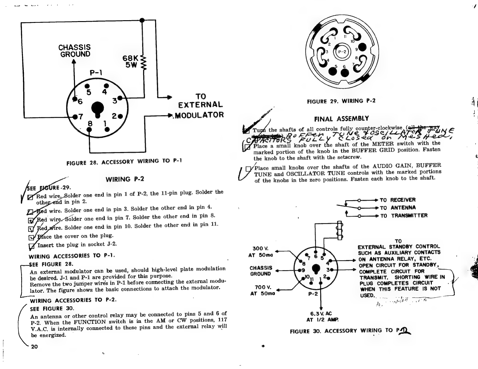
SSS
68K
SW
TO
EXTERNAL
.MODULATOR
FIGURE
28.
ACCESSORY
WIRING
TO
P-1
WIRING
P-2
EE
RE
-29.
Red
wire,
Solder
one
end
in
pin
1
of
P-2,
the
11-pin
plug.
Solder
the
othey-etid
in
pin
2.
‘a
wire.
Solder
one
end
in
pin
3.
Solder
the
other
end
in
pin
4.
d
wir
Solder
one
end
in
pin
7.
Solder
the
other
end
in
pin
8.
aa
re.
Solder
one
end
in
pin
10.
Solder
the
other
end
in
pin
11.
ie
ace
the
cover
on
the
plug.
Insert
the
plug
in
socket
J-2.
WIRING
ACCESSORIES
TO
P-1.
EE
FIGURE
28.
An
external
modulator
can
be
used,
should
high-level
plate
modulation
be
desired.
J-1
and
P-1
are
provided
for
this
purpose.
Remove
the
two
jumper
wires
in
P-1
before
connecting
the
external
modu-
lator.
The
figure
shows
the
basic
connections
to
attach
the
modulator.
WIRING
ACCESSORIES
TO
P-2.
SEE
FIGURE
30.
An
antenna
or
other
control
relay
may
be
connected
to
pins
5
and
6
of
P-2.
When
the
FUNCTION
switch
is
in
the
AM
or
CW
positions,
117
V.A.C.
is
internally
connected
to
these
pins
and
the
external
relay
will
be
energized.
—
20
FIGURE
29.
WIRING
P-2
FINAL
ASSEMBLY
the
shafts
of
all
roe
ie
on
percep
iby
eee
=
Poker.
Lecgy
@
FuL.e
SLosea”
dh
2.
fool;
Place
a
small
knob
over
the
shaft
of
the
METER
switch
with
the
marked
portion
of
the
knob
in
the
BUFFER
GRID
position.
Fasten
the
knob
to
the
shaft
with
the
setscrew.
ra
Place
small
knobs
over
the
shafts
of
the
AUDIO
GAIN,
BUFFER
TUNE
and
OSCILLATOR
TUNE
controls
with
the
marked
portions
of
the
knobs
in
the
zero
positions.
Fasten
each
knob
to
the
shaft.
300
V.
AT
50ma
CHASSIS
GROUND
7OOV.
AT
50ma
=
Buea.
RECEIVER
TO
ANTENNA
’
t_.
.
TO
TRANSMITTER
TO
EXTERNAL
STANDBY
CONTROL
SUCH
AS
AUXILIARY
CONTACTS
ON
ANTENNA
RELAY,
ETC.
OPEN
CIRCUIT
FOR
STANDBY,
COMPLETE
CIRCUIT
FOR
TRANSMIT,
SHORTING
WIRE
IN
PLUG
COMPLETES
CIRCUIT
WHEN
THIS
FEATURE
IS
NOT
USED,
og,
|
y
nth
ae)
6.3
V.
AC
AT
1/2
AMP.
FIGURE
30.
ACCESSORY
WIRING
TO
Pp)
Suet
aa
oe
athe
Table of contents
Other Allied Radio Transmitter manuals


