Allied Radio knight-kit tT-50 User manual

Allied
knight-kit
50-WATT
TRANSMITTER
83
YX
255
ata
se
ALLIED
RADIO
cOR
PORATION
100
N.
WESTERN
AVE...
CHICAGO
80.
ILL.
HAYMARKET
1-6800
38K095
:
730012C-13-AP-55a
Entire

CAPACITOR
AND
RESISTOR
COLOR
CODE
RESISTOR-MICA
CAPACITOR
COLOR
CODE
Telerance
Multipiter
%
:
I
|
PeudmAarxwryHo
*Applies
to
capacitors
oniy
Aac
ones
1
=
z|||
EH
Peed
Gil
Y
HOW
TO
DETERMINE
THE
VALUE
OF
A
RESISTOR
A—
First
significant
figure
{digit}
of
resistance
in
ohms.
8
—
Second
significant
figure.
C
—~
Decimal
multiplier
(number
of
zeros
to
be
added).
D—
Tolerance
of
resistor
in
percent.
No
color
is
20%.
EXAMPLE;
A
resistor
has
the
followihg
color
bands;
A,
yellow;
B,
violet;
C,
yel-
low;
and
D,
silver.
The
significant
figures
are
4
and
7
(47)
and
the
multiplier
is
10,000.
The
vaiue
of
resistance
is
470,006
ohms
and
the
tolerance
is
+10%.
TUBULAR
PAPER
CAPACITOR
COLOR
CODE
Es
ABCO
E
MOW
YO
DETERMINE
THE
VALUE
OF
A
PAPER
TUSULAR
CAPACITOR
A—
First
significant
figure
(digit)
of
Capacitance
in
uf.
B —
Second
significant
Agure.
C
—»
Decimal
multiplier
(number
of
zeros
to
be
added).
D
—
Tolerance
uf
capacitor
in
percent.
KE
—
Voltage
rating.
EXAMPLE:
A
paper
tubular
capacitor
has
the
following
color
Sands:
A,
brown:
B.
green;
C,
orange;
D,
black;
and
¥,
yellow.
The
significant
figures
are
1
and
5
(15)
and
the
decimal
muitipiier
is
1.000.
The
value
of
capacitance
is
15,000
zat.
The
tolerance
Is
+20%.
The
voltage
rating
is
400
V
DC.
2
a
RETWA
WHITE
MILITARY
BLACK
8!
SIGNIFICANT
FIGURE
2°
signuicant
FIGURE
TOLERANCE
HOW
7O
DETERMINE
THE
VALUE
OF
A
MICA
CAPACITOR
EXAMPLES:
A
capacitor
with
a
6
det
code
(new
RETMA
standard
REC-115A
and
military
MYL-C-5A}
has
the
following
markings.
Top
row,
left
to
right,
white.
green,
brown; bottom
row,
right
to
left,
brown,
red,
red.
The
frst
color
white
indicates
mica.
The
significant
figures
are
5
and
1
(3%),
and
the
dectrna?
multipiler
is
10.
So
the
capacitance
Is
510
uzf.
Tolerance
is
+2%.
For
most
general
applications
the
characteristic
ean
be
ignored.
A
capacitor
with
a
6
dot
code
hax
the
fotiowing
markings:
Top
row,
left
to
right,
brown,
orange,
red;
bottom
row,
Tight
to
left.
brown,
red,
green.
Since
the
first
dot
is
neither
black
or
white,
this
is
the
obsolete
RETMA
code.
The
significant
figures
are
1, 3,
and
2
(132),
and
the
decimal
muitiplier
is
10.
So
the
capacitance
is
1326
unt.
Tol-
erance
is
2%,
Voltage
rating
is
$00
V
DC.
CERAMIC
CAPACITOR
COLOR
CODE
[2%
SIGNIFICANT
FicURE
48%
SIGNIFICANT
FIGURE
-~
TOLERANCE
bn
OECIMAL
MULTIPLIER
HOW
1Q
DETERMINE
THE
VALUE
OF
A
CERAMIC
CAPACITOR
EXAMPLES:
A
ceramic
tubular
capacitor
has
the
following
color
bands:
Black,
red, red,
red,
green.
The
significant
figures
are
2
and
2
(22),
and
the
decimai
muitiplier
is
100.
The
capacitance
is,
therefore,
2200
nat,
Tole
erance
is
+5%.
Temperature
coefficient
is
0.
Voltage
rating
is
always
500
¥.
A
ceramic
disc
capacitor
has
the
following
5-det code:
Red,
brown,
green,
red,
green.
The
significant
figures
are
1
and
§
(15),
and
the
decimal
muitiplier
is
100.
The
capacitance
is,
therefore,
1500
wut.
‘The
tolerance
is
+&%.
The
temperature
coefficients
~~
75.
Voltage
rating
is
always
500
¥.
A
ceramic
disc
capacitor
has
the
following
3-dot
code:
Green,
brown,
brown.
The
significant
figures
are
¥
and
1
(S31},
and
the
decimal
multiplier
is
10,
Therefore,
the
tapacity
ta
510
«et.
Voltage
rating
is
always
500
V
and
the
tolerance
is
alwaya
—
0.
2°.
SIGNIFICANT
FIGURE
DECIMAL
MULTIPLIER
DECIMAL
MULTIPLIER
+4
crete
emo

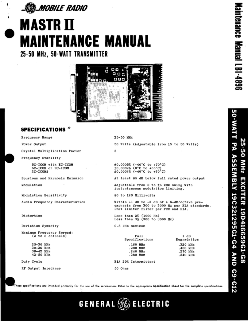
THE
KNIGHT
50-WATT
TRANSMITTER
SPECIFICATIONS
Output
Frequencies...
3.5—-
4
mec
Modulation
.......
Provision
is
made
for
the
con-
7.0—
7.3
me
nection
of
an
external
modu-
14.0—14.3
me
lator.
21.0—21.5
me
27.0—27.2
me
VFO
Operation.....
The
KNIGHT
50-Watt
Amateur
28.0—-29.7
me
Transmitter
may
be
controlled
Power
Input
to
Final
Amplifier
...50
watts
minimum
on
all
bands.
Frequency
Control
.
.
Quartz
crystal
or
external
VFO.
Output
Circuit......
Pi-network,
capable
of
matching
unbalanced
loads
between
50
and
1200
ohms.
Will
tune
out
large
amounts
of
reactance.
Connec-
tion
to
the
output
is
through
an
SO-239
type
coaxial
connector.
Tubes
............
6AG7
crystal
oscillator-multipli-
er
(buffer-multiplier
when
VFO
used)
807
power
amplifier
5U4G
rectifier.
HOW
TO
BUILD
THE
KNIGHT
The
KNIGHT
50-Watt
Transmitter
is
a
complete,
self-contained
crystal-controlled
CW
transmitter.
It
has
a
final
amplifier
power
input
of
50
watts
on
the
80,
40,
20,
15,
11,
and
10
meter
amateur
bands.
The
various
bands
are
selected
by
means
of
a
bandswitch.
The
pi-network
output
circuit
in
the
amplifier
stage
permits
matching
a
wide
variety
of
antennas
and
feed
lines.
The
pi-network
also
provides
a
considerable
de-
gree
of
harmonic
attenuation,
to
aid
in
the
reduction
of
TVI
(Television
Interference).
The
KNIGHT
50-Watt
Transmitter
has
features
which
appeal
to
the
novice
as
well
as
the
experienced
amateur.
The
50-watt
power
is
more
than
adequate
for
world-wide
contacts.
Changing
bands
has
been
reduced
to
simply
turning
the
bandswitch,
resonating
two
circuits,
and
adjusting
the
loading.
Band
changing
is
thus
a
matter
of
a
few
seconds.
There
are
no
coils
to
change.
Before
starting
to
build
your
KNIGHT
Transmitter
check
each
part
against
the
Parts
List
on
page
20.
If
you
are
unable
to
identify
some
of
the
parts
by
sight,
locate
them
on
the
pictorial
diagrams.
Capacitor
and
resistor
values,
if
not
printed
on
the
part,
can
be
found
with
the
aid
of
the
Color
Code
Chart.
Hardware
is
listed
in
the
last
part
of
the
Parts
List.
To
keep
our
kits
at
the
lowest
possible
price,
we
fre-
quently
weigh
hardware
rather
than
count
it.
There-
fore,
do
not
be
concerned
if
more
nuts
and
machine
by
any
VFO
supplying
8
to
10
volts
across
22,000
ohms,
and
delivering
output
in
the
160,
80,
or
40
meter
bands.
The
KNIGHT
VFO
is
ideally
suited.
TVI
Reduction......
The
transmitter
is
completely
shielded
by
its
cabinet,
with
firm
metal-to-metal
seals
provided
at
all
metal
junctions.
The
chassis
is
well
bonded
to
both
front
and
rear
of
the
cabinet,
thus
assur-
ing
minimum
harmonic
radia-
tion.
Filtering
and
bypassing
of
AC
and
keying
leads
is
provided,
and
generous
bypassing
of
the
meter
and
heater
circuits
is
in-
cluded.
Cabinet
Size.......
1014”
long
by
814”
high
by
81,”
deep.
50-WATT
TRANSMITTER
screws
for
example,
are
supplied
than
are
specified
in
the
Parts
List.
The
only
tools
required
for
building
your
KNIGHT
Transmitter
are:
Long-nose
pliers,
diagonal
cutters,
screwdriver,
set-screw
driver,
and
a
soldering
iron.
A
good
set
of
tools
is
listed
at
the
end
of
the
Parts
List.
Study
the
pictorial
diagrams
and
note
how
the
parts
are
mounted.
These
pictorial
diagrams
show
the
actual
location
of
all
parts
and
wiring.
The
schematic
dia-
gram
shows
how
the
parts
are
connected
electrically
and
is
helpful
in
understanding
how
the
circuits
work.
The
step-by-step
instructions
were
prepared
by
a
skilled
technician
while
he
was
actually
building
the
KNIGHT
Transmitter.
Therefore,
they
are
the
best
and
fastest
way
of
assembling
this
transmitter.
We
suggest
that
you
read
through
the
instructions
BE-
FORE
you
build
the
transmitter.
This
will
help
you
to
familiarize
yourself
with
the
procedure
and
avoid
possible
errors.
We
recommend
using
the
[]
to
check
off
each
step
after
it
is
completed.
Each
step
is
clearly
illustrated
on
an
accompanying
line
drawing.
Some
builders
prefer
to
cross
out
each
wire
and
component
on
the
drawings
with
a
colored
pencil
after
it
is
installed.
While
an
excellent
way
to
avoid
mistakes,
and
highly
recommended
by
us,
this
procedure
results
in
drawings
that
are
difficult
to
re-
use.
For
this
reason
each
wiring
view
is
reproduced
on
a
separate,
folded
sheet
of
paper.
3

FIGURE
1.
MOUNTING
THE
PARTS
UNDERNEATH
THE
CHASSIS

MECHANICAL
ASSEMBLY
|
MOUNTING
THE
PARTS
ON
THE
CHASSIS
SEE
FIGURE
1.
(]
Insert
a
rubber
grommet
in
each
of
the
five
holes
marked
“GROMMET”
on
Figure
1.
Grommets
are
installed
by
squeezing
them
into
place.
[]
Install
J-3,
the
coaxial
cable
receptacle,
from
out-
side
the
rear
of
the
chassis,
in
the
hole
with
four
small
holes
around
it.
Use
four
thin
4-36x34”
screws
and
four
matching
nuts
to
fasten
J-3.
NOTE:
There
are
only
six,
~,”
long
6-32
screws
supplied.
These
six
screws
will
be
used
in
the
next
few
steps.
[]
Attach
the
fuse
holder,
inside
the
chassis,
using
one
6-32x;5;”
screw
and
a
matching
nut.
[_.]
From
inside
the
back
of
the
chassis,
put
a
6-32x
=”
screw
through
the
hole
beside
J-3.
Put
a
lockwasher
and
hex
nut
on
the
screw
outside
the
chassis
and
tighten
the
nut.
FIGURE
2.
HOW
TO
MOUNT
THE
RUBBER
FEET
ON
THE
CABINET
[(]
As
shown
in
Figure
2,
put
a
6-32x,3,”
screw
through
the
large
hole
in
each
of
the
four
rubber
cabinet
feet
so
the
screw
head
fits
into
the
large
hole.
Push
the
protruding
threaded
ends
of
the
screws
through
the
bottom
of
the
cabinet
and
fasten
them
with
hex
nuts
inside
the
cabinet.
(J
From
inside
the
rear
of
the
chassis,
mount
J-4,
one
of
four
8-pin
sockets,
in
the
large
hole.
Use
two
6-32x14”
screws
and
nuts
to
fasten
J-4.
The
keyway,
or
notch
in
the
large
center
hole
must
be
toward
the
grommet.
Fasten
TS-1,
a
3-terminal
strip,
with
the
J-4
mounting
screw
next
to
the
grommet.
A
lockwasher
is
used
between
the
chassis
and
socket
under
the
nut
mounting
TS-1
and
J-4.
(J
Fasten
V-3,
an
8-pin
socket,
with
two
6-32x'/,”
screws
and
matching
nuts,
in
the
hole
near
the
rear
center
of
the
chassis.
The
keyway
must
be
away
from
the
two
large
holes
next
to
the
socket.
A
solder
lug
is
attached
on
top
of
the
chassis
under
the
V-3
mounting
screw
near
the
grommet.
Use
a
lockwasher,
next
to
the
chassis,
under
the
nut
that
fastens
the
solder
lug.
6-32
X
1/4"
of
HEX
—
S
©
H
x
B
ww
LOCKWASHER
LOCKWASHER~,
ex
BY
:
a“
CUTAWAY
SECTION
OF
CHASSIS
NOTE
POSITION
OF
LARGE
VENT
HOLE
IN
RELATION
TO
KEYWAY
ON
K
1-1/2"
6-32
Se
Sache
SCREWS
FIGURE
3.
HOW
TO
MOUNT
V-2
(]
V-2
is
a
ceramic
5-pin
sacket.
The
keyway
of
this
socket
is
a
raised
dot.
The
keyway
must
be
posi-
tioned
toward
the
rear
of
the
chassis.
As
shown
in
Figure
3,
put
the
two
6-32x114”
screws
thru
the
holes
in
the
chassis
from
the
top.
Place
the
two
1”
spacer
bushings
on
the
screws
and
then
put
the
socket
on
the
two
screws.
Put
a
lockwasher
on
each
screw
and
tighten
two
6-32
nuts
on
them.
(]
Install
V-1,
an
8-pin
socket,
with
two
6-32x14”
screws
and
nuts
in
the
hole
near
the
fuse
holder.
The
keyway
must
be
toward
the
rear
of
the
chassis.
Fasten
TS-5,
a
3-terminal
strip
with
the
V-1
mount-
5

ing
screw
and
nut
nearest
to
the
fuse
block.
Use
a
lockwasher
next
to
the
chassis
under
the
nut
hold-
ing
TS-5.
[-]
Mount
TS-2,
a
2-terminal
strip,
with
a
6-32x14”
screw
and
nut.
[]
Mount
TS-3,
a
5-terminal
strip,
with
a
6-32x14”
screw,
a
lockwasher
next
to
the
chassis,
and
a
nut.
L]
Mount
J-1,
an
8-pin
socket,
in
the
large
round
hole
on
the
front
of
the
chassis
with
two
6-32x14,”
screws
and
nuts.
The
keyway
must
be
positioned
away
from
the
center
of
the
chassis.
[]
Mount
S-4,
the
6-terminal
slide
switch,
in
the
rec-
tangular
hole
in
the
front
center
of
the
chassis
with
two
6-32x1!/,”
screws
and
nuts.
[]
Mount
S-1,
the
2-terminal
slide
switch,
in
the
remaining
rectangular
hole
in
the
front
of
the
chassis
with
two
6-32x14”
screws
and
nuts.
This
switch
must
be
positioned
so
that
the
center
ter-
minal
is
away
from
the
open
side
of
the
chassis.
{_]
T-1
is
the
large
transformer.
Referring
to
Figure
1,
locate
the
position
in
which
T-1
is
mounted
on
top
of
the
chassis.
Begin
mounting
T-1
by
pushing
the
two
green
and
two
black wires
through
the
large
hole
near
the
corner
of
the
chassis.
Push
the
two
yellow,
two
red
and
the
red-yellow
wires
through
the
other
hole.
Fasten
T-1
with
four
8-32x1/,”
screws
through
the
top
of
the
chassis;
put
a
lock-
washer
on
each
screw
before
tightening
the
nuts.
(0
Referring
to
Figure
1,
locate
the
position
for
mounting
L-7,
the
filter
choke,
on
top
of
the
chassis.
The
side
with
the
wires
must
be
toward
the
grommet.
Fasten
L-7
with
two
6-32x14,”
screws,
lockwashers,
and
nuts.
Push
the
two
wires
through
the
grommet.
[}
Mount
J-2,
a
phone
jack,
in
the
round
hole
next
to
J-1.
Use
a
34”
hex
nut
to
retain
J-2.
Position
the
terminals
as
shown
in
Figure
1.
ATTACHING
THE
FRONT
PANEL
TO
THE
CHASSIS
SEE
FIGURE
4.
[]
From
the
outside
of
the
front
panel,
put
the
pilot
light
jewel
through
the
round
hole
between
the
two
small
rectangular
holes
near
the
bottom.
Fasten
it
with
a
large
7,”
hex
nut.
(|
Fit
the
front
panel
to
the
chassis.
The
threaded
bushing
on
the
pilot
light
jewel
fits
through
the
one
open
hole
on
the
front
of
the
chassis.
The
switch
buttons
fit
through
the
rectangular
holes
in
the
panel.
Put
a
flat
washer
and
a
nut
on
the
‘bushing
of
J-2.
Put
the
pilot
light
socket
on
the
6
PILOT
LIGHT
JEWEL
SOTTOM
OF
FRONT
PANEL
FIGURE
4.
HOW
TO
ATTACH
THE
FRONT
PANEL
TO
THE
CHASSIS
pilot
light
jewel
and
fasten
it
with
a
large
hex
nut.
See
Figure
13
for
the
position
of
the
pilot
light
socket.
MOUNTING
PARTS-ON
TOP
OF
THE
CHASSIS
SEE
FIGURE
6.
(J
Install
S-3,
the
2-section
ceramic
bandswitch,.
in
the
hole
just
below
the
very
large
round
hole
in
the
center
of
the
front
panel.
Position
the
terminals
as
shown
in
Figure
6.
Use
a
large
lockwasher
on
the
back
of
the
panel,
a
large
flat
washer
on
the
front
of
the
panel
and
a
large
hex
nut
to
fasten
S-3.
NOTE:
There
are
two
large
coils
wound
on
ceramic
forms
supplied
with
the
kit.
Coil
L-2
has
5
terminals
and
coil
L-6 has
6
terminals.
(J
Prepare
L-6,
the
6-terminal
coil,
for
installation
by
attaching
the
spade
screws
as
shown
in
Figure
5.
Note
that
the
flat
side
of
the
spade
screws
must
be
against
the
coil.
On
a
6-32x114”
screw
put
a
solder
lug,
a
spade
screw,
and
a
fiber
washer.
Push
the
screw
through
the
holes
in
the
coil
from
the
side
opposite
the
terminals.
On
the
threaded
end
BOTTOM
VIEW
OF
CO,
SOLDER
LUG
‘SPADE
SCREW
FIBER
WASHERS
SPADE
SCREW
FIGURE
5.
MOUNTING
L-2
AND
L-6

SSN
aaaaay
aD
Mla
i)
y
ANTENNA
LOADING
CAPACITOR
SOLDER
LUG
©
AMPLIFIER
COIL
I
y
A
——
—
.—~
=,
Dp
la
2
Vs
Se
(SUSE
5
ASCONNECTOR
——
=
grounp
ONNECTION:
a
FIGURE
6.
MOUNTING
THE
PARTS
ON
TOP
OF
THE
CHASSIS

REAR
VIEW
OF
S-2
6-32
Xx
+
NUT
LOCKWASHER
6-32
X
+
SCREW
SOLDER
LUG
WASHER
\
98
i
(
RNR
|
LAAT
i,
he
oT
SWITCH
MOUNTING
PLATE
FIGURE
7.
HOW
TO
MOUNT
C-14,
S-2
AND
C-12
of
the
screw
put
a
fiber
washer,
a
spade
screw
and
([]
Study
Figure
7.
Mount
C-14,
C-12,
S-2
and
the
a
6-32
nut.
CAUTION:
This
nut
must
be
fastened
carefully.
If
it
is
tightened
too
much
the
coil
form
may
break.
Mount
L-6
by
putting
the
two
spade
screws
through
the
holes
in
the
chassis
as
shown
in
Figure
6.
Put
a
lockwasher
on
both
spade
screws
under
the
chassis.
Put
a
solder
lug
on
the
spade
screw
nearest
to
V-2.
Fasten
the
coil
with
two
6-32
nuts.
Attach
spade
screws
to
L-2
in
the
same
way
they
were
fastened
to
L-6
(see
Figure
5)
except
that
two
solder
lugs
are
used,
one
on
each
side.
Mount
L-2
in
the
position
shown
in
Figure
6.
Put
a
small
lockwasher
on
both
spade
screws
under
the
chassis
and
a
solder
lug
on
the
spade
screw
near
the
two
grommets.
Fasten
the
spade
screws
with
two
6-32
hex
nuts.
There
are
three
tuning
capacitors
supplied
with
the
kit.
The
capacitor
with
two
separate
sections
of
plates
is
C-14.
The
longer
of
the
two
other
capacitors
is
C-12.
The
shorter
is
C-4.,
switch
mounting
plate
as
shown
in
Figure
7.
Note
that
the
terminals
of
S-2
are
positioned
toward
the
center
of
the
chassis.
Put
a
hex
nut
seven
full
turns
over
the
threaded
shaft
bushing
of
C-4.
Put
the
shaft
of
C-4
through
the
hole
in
the
front
panel
above
J-2.
Put
a
flat
washer
on
the
shaft
of
C-4.
Tighten
another
hex
nut
on
C-4
to
fasten
it.
Mount
the
34”
ceramic
standoff
insulator
with
a
6-32x14”
screw
up
through
the
chassis.
The
insu-
lator
mounting
hole
is
located
between
L-6
and
L-7.
Put
three
solder
lugs
on
a
6-32x14”
screw
and
screw
it
into
the
top
of
the
insulator.
Do
not
fasten
this
screw
more
than
“finger”
tight.
Mount
a
solder
lug
on
the
back
of
C-14
using
a
lockwasher,
one
6-32x14”
screw,
and
a
matching
nut.
See
Figure
7
for
the
location.
[]
Mount
M-1,
the
indicating
meter,
in
the
large
hole
in
the
center
of
the
front
panel.
Use
two
4-36x34”
screws
and
matching
nuts
to
mount
M-1.

{[]
Remove
a
nut
from
each
terminal
on
M-1.
Put
a
solder
lug
on
each
terminal,
position
them
down-
ward,
and
replace
each
nut.
WIRING
AND
SOLDERING
How
well
electronic
equipment
works
will
often
depend
upon
the
quality
of
workmanship
used
in
its
construction.
For
this
reason
the
following
sugges-
tions
are
given.
These
wiring
and
soldering
hints
are
mainly
for
the
beginner
in
electronics,
however,
even
the
advanced
enthusiasts
may
benefit
from
a
brief
review.
The
insulated
wire
furnished
with
this
kit
is
cut
to
length
and
the
ends
are
stripped.
Each
different
col-
ored
wire
is
a
different
length,
therefore,
be
sure
to
use
the
color
specified
in
each
of
the
wiring
steps.
A
long
piece
of
bare
wire
is
included.
Whenever
it
is
necessary
to
use
some
of
it,
the
exact
length
of
the
piece
required
is
given.
The
flexible
tubing
supplied
is
called
“spaghetti”.
Spaghetti
is
used
to
cover
the
bare
end
leads
of
some
of
the
components
and
portions
of
some
of
the
bare
wires
where
there
is
danger
they
will
touch
other
bare
wires
or
the
chassis.
FIGURE
8.
HOW
TO
CONNECT
A
WIRE
TO
A
TERMINAL
The
proper
way
to
connect
a
wire
or
lead
to
a
solder
terminal
is
shown
in
Figure
8.
To
insure
a
good
me-
chanical
connection,
squeeze
the
wire
against
the
ter-
minal
with
your
long
nose
pliers
after
it
has
been
hooked
on.
Make
sure
the
wire
leads
and
terminals
are
clean
before
connecting
them.
If
necessary,
scrape
them
with
a
pocket
knife
until
any
foreign
substance,
such
as
wax
is
removed.
Be
extremely
careful
not
to
nick
the
wire
with
the
knife,
or
it
may
break
when
it
is
bent.
Unless
otherwise
stated,
all
the
leads
on
the
resist-
ors,
capacitors,
and
transfromer
should
be
as
short
as
possible.
Figure
9
illustrates
the
best
way
to
connect
a
component.
As
shown,
the
end
leads
should
be
pulled
through
the
terminals
so
that
the
parts
are
tightly
mounted.
After
a
lead
is
pulled
through
a
terminal,
bend
it
around
the
terminal
and
cut
off
the
excess
wire.
Me
11
BEST
WAY
\\
'
{MAKE
ENO
LEAD
AS
SHORT
AS
POSSIBLE}
‘
FIGURE
9.
THE
BEST
WAY
TO
CONNECT
A
COMPONENT
USE
ONLY
ROSIN
CORE
SOLDER
USE
THE
ROSIN
CORE
SOLDER
SUPPLIED
WITH
THE
KIT.
KITS
SOLDERED
WITH
ACID
CORE
SOLDER,
ACID
FLUX,
OR
WITH
IRONS
CLEANED
ON
A
SAL
AM-
MONIAC
BLOCK
WILL
SOON
CORRODE
AND
WILL
NOT
WORK
LONG.
SUCH
KITS
ARE
NOT
ELIGIBLE
FOR
REPAIR
OR
SERVICE.
Before
soldering,
the
tip
of
your
soldering
iron
must
be
properly
tinned.
To
do
this,
clean
the
surfaces
of
the
tip
with
steel
wool,
or
a
fine
file,
until
the
bright
copper
surface
is
exposed.
Plug
the
iron
in
and
allow
it
to
heat
until
it
melts
solder.
Apply
solder
to
the
tip
until
it
is
well
covered
with
a
thin
coat.
Wipe
off
the
excess
solder
with
a
rag.
The
tip
should
now
be
shiny.
Re-tin
the
tip
whenever
it
becomes
covered
with
a
layer
of
scale.
Before
soldering
a
connection
be
sure
the
iron
is
hot
enough
to
melt
solder.
Preheat
the
connection
by
holding
the
tip
of
the
iron
against
the
joint
to
be
soldered.
After
the
joint
is
heated,
apply
solder
to
the
joint,
not
to
the
iron
tip.
Use
only
enough
solder
to
fill
the
crevices
and
cover
all
of
the
wire
and
the
terminal.
Do
not
solder
any
connection
until
told
to
do
so.
Right
after
a
connection
is
soldered
it
should
not
be
jiggled
or
moved
until
the
solder
has
a
chance
to
cool
and
‘‘set”.
If
a
soldered
connection
is
disturbed
before
it
has
cooled
it
will
have
a
frosty
appearance.
This
condition
is
called
a
“cold solder
joint”.
A
cold
solder
joint
is
not
strong
and
may
crumble
apart.
If
you
should
accidentally
make
a
cold
solder
joint,
re-
heat
it
with
your
soldering
iron
and
add
a
very
small
amount
of
fresh
solder.
After
you
have
soldered
a
connection,
push
any
in-
sulation
or
spaghetti
as
close
to
the
connection
as
possible.
This
will
prevent
close
connections
from
touching
one
another
and
causing
a
short.
9

weedeses
,
we
setts
oI
Ss
a
g
x
OO.
oe
°o
m
a
¢
bl
[i ag
3
ny
ae
=
ties
i
7
a
EEA
Q-
Picco
ce
Si
GROUND
CONNECTION
:
WIRING
THE
TOP
OF
THE
CHASSIS
FIGURE
10.

When
wiring
the
contacts
of
switches,
be
careful
not
to
bend
the
switch
contacts;
this
will
reduce
the
spring
pressure
of
the
contacts.
You
are
now
ready
to
wire
your
KNIGHT
Trans-
mitter.
Remember,
use
only
rosin
core
solder.
WIRING
ON
TOP
OF
THE
CHASSIS
SEE
FIGURE
10.
[_]
Connect,
but
do
not
solder,
one
lead
of
C-16,
a
.005
MFD
disc
capacitor,
to
either
solder
lug
on
M-1.
Connect,
but
do
not
solder,
the
other
lead
of
C-16
to
the
other
solder
lug
of
M-1.
(]
Solder
a
blue
wire
to
the
terminal
of
M-1
not
marked
“+”.
Push
the
other
end
of
this
wire
through
the
grommet
which
is
almost
directly
be-
low
M-1.
Turn
the
chassis
over
and
solder
the
blue
wire
to
terminal
2
of
S-4,
which
is
in
the
center
of
the
front
of
the
chassis.
[]
Solder
another
blue
wire
to
the
terminal
of
M-1
marked
“+”.
Push
this
blue
wire
through
the
same
grommet
as
the
other
wire.
The
other
end
will
be
connected
later.
CL]
Connect,
but
do
not
solder,
a
gray
wire
to
terminal
9
of
S-3A
(the
BAND
switch).
Push
the
free
end
of
this
wire
down
through
the
grommet
just
below
terminal
9
of
S-3A
where
it
will
be
connected
later.
WARNING:
The
wiring
from
the
BAND
switch,
S-3,
to
the
coils,
L-2
and
L-6,
must
be
as
short
and
straight
as
possible.
[J
Connect,
but
do
not
solder,
one
lead
of
C-5,
a
.005
disc
capacitor,
to
terminal
9
of
switch
S-3A.
Solder
the
other
lead
of
C-5
to
solder
lug
2
at
the
bottom
of
coil
L-2.
(1
Solder
a
134”
bare
wire
to
terminal
7
of
S-3A.
Put
a
34”
piece
of
spaghetti
on
this
wire.
Solder
the
other
end
of
this
wire
to
terminal
3
of
L-2.
[]
Solder
a
134”
bare
wire
to
terminal
6
of
S-3A.
Connect,
but
do
not
solder,
the
other
end
of
this
wire
to
terminal
2
of
L-2.
[]
Solder
a
2%”
bare
wire
to
terminal
8
of
S-3A.
Solder
the
other
end
of
this
wire
to
terminal
4
of
L-2.
[]
Solder
a
314”
bare
wire
to
terminal
9
of
S-3A.
Connect,
but
do
not
solder,
the
other
end
of
this
wire
to
terminal
5
of
L-2.
{]
Solder
one
lead
of
R-2,
a
large
1-watt
2700
ohm
resistor,
with
the
color
stripes
red,
violet,
and
red,
to
terminal
5
of
L-2.
Solder
the
other
lead
of
R-2
to
terminal
2
of
L-2.
(J
Solder
a
21%”
bare
wire
to
terminal
2
of
C-4,
the
ceramic
insulated
capacitor
next
to
L-2.
Connect,
but
do
not
solder,
the
other
end
of
this
wire
to
terminal
1
of
L-2.
(]
Solder
one
end
of
a
yellow
wire
to
terminal
1
of
L-2.
Push
the
other
end
of
this
wire
down
through
the
grommet
just
below
terminal
1
of
L-2.
This
end
will
be
connected
later.
[]
Solder
one
end
of
a
1”
bare
wire
to
terminal
1
of
C-4.
Solder
the
other
end
of
this
wire
to
solder
lug
1
on
L-2.
([]
Solder
a
2”
bare
wire
to
terminal
6
of
coil
L-6.
Connect,
but
do
not
solder,
the
other
end
of
this
wire
to
terminal
2
of
C-12,
the
large
ceramic
in-
sulated
capacitor
near
L-6.
(]
Solder
a
134”
bare
wire
to
terminal
5
of
L-6.
Solder
the
other
end
of
this
wire
to
terminal
5
of
S-3B.
(]
Solder
a
2”
bare
wire
to
terminal
4
of
S-3B.
Solder
the
other
end
of
this
wire
to
terminal
4
of
L-6.
[]
Solder
a
2”
bare wire
to
terminal
3
of
S-3B.
Solder
the
other
end
of
this
wire
to
terminal
3
of
L-6.
[]
Solder
a
214”
bare
wire
to
terminal
2
of
S-3B.
Solder
the
other
end
of
this
wire
to
terminal
2
of
L-6,
[]
Connect
the
following
terminals
together
with
a
414”
bare
wire
in
the
order
given:
terminal
1
of
S-3B,
terminal
1
of
L-6,
terminal
4
of
C-14
anc
terminal
3
of
C-14.
Solder
each
terminal.
L]
Solder
a
white-brown
wire
to
terminal
2
of
C-14
Push
the
other
end
of
this
wire
through
the
grom-
met
directly
below
it
in
the
chassis.
[]
Connect
the
following
terminals
together
with
<
43/4”
bare
wire:
The
solder
lug
at
the
base
of
L-6
terminal
3
of
C-12,
and
the
solder
lug
screwed
or
the
back
of
C-14.
Solder
only
the
first
twc
terminals.
(]
As
shown
in
Figure
11,
(see
next
page)
solder
on«
lead
of
C-15,
a
700
MMFD
mica
capacitor,
to
ter
minal
1
of
S-2.
Solder
the
other
lead
of
C-15
to
the
solder
lug
on
the
back
of
C-14.
(J
As
shown
in
Figure
11,
solder
one
end
of
a
rec
wire
to
terminal
2
of
S-2.
Solder
the
other
end
o:
this
wire
to
terminal
1
on
C-14.
(
Solder
one
lead
of
C-13,
a
.0015
MFD
dise
capaci
tor,
to
terminal
2
of
C-12.
Solder
the
other
lea
of
C-13
to
the
closest
solder
lug
on
top
of
th
standoff
insulator.
L-3
and
L-4
are
identical
parasitic
chokes.
They
ar
slightly
over
14”
long
in
the
body
and
have
about
|
turns
of
wire
wound
on
them.
[]
Cut
one
lead
of
L-4
to
34”.
Solder
this
lead
t
the
metal
plate
connector
so
that
there
is
4
spacing
between
the
end
of
the
coil
and
the
con
nector.
Leave
the
other
lead
full
length.
Solde
it
to
the
closest
empty
solder
lug
on
top
of
th
standoff
insulator.
.

FIGURE
11.
HOW
TO
WIRE
C-15
L-5
is
a
2.5
millihenry
radio-frequency
choke.
It
s
easily
identified
by
its
four
separate
windings.
‘]
Pull
one
lead
of
L-5
as
close
as
possible
to
the
remaining
empty
solder
lug
on
the
standoff
insula-
tor.
Solder
this
lead
of
L-5.
Make
a
small
hook
in
the
other
lead
of
L-5
as
close
to
the
body
of
the
choke
as
possible
and
cut
off
the
excess
lead.
‘|
Solder
one
lead
of
C-11
(make
these
connections
as
close
as
possible),
a
.005
disc
capacitor,
to
the
solder
lug
near
V-3.
Connect,
but
do
not
solder,
the
other
lead
of
C-11
to
the
hook
on
L-5.
]
Solder
an
orange
wire
to
the
hook
on
L-5.
Push
the
other
end
of
this
wire
through
the
grommet
next
to
L-7.
INSTALLING
THE
SHIELD
PARTITION
]
As
shown
in
Figure
12,
install
the
shield
partition.
Note
that
a
solder
lug
and
terminal
strip
TS-4
are
mounted
with
the
shield
fastening
nuts.
The
spade
screws
must
be
attached
to
the
sides
of
the
shield
as
illustrated
in
Figure
12.
WIRING
THE
CHASSIS
SEE
FIGURE
13.
O
O
lS
elk:
Mah
1s]
O
a
Solder
the
short
black
wire
from
T-1,
the
power
transformer,
to
terminal
1
of
F-1,
the
fuse
holder.
Solder
the
long
black
wire
from
T-1
to
terminal
2
of
S-1.
Solder
either
red
wire
from
T-1
to
pin
6
of
V-3.
Solder
the
other
red
wire
from
T-1
to
pin
4
of
V-3.
Solder
either
yellow
wire
from
T-1
to
pin
2
of
V-3.
Connect,
but
do
not
solder,
the
other
yellow
wire
from
T-1
to
pin
8
of
V-3.
Connect,
but
do
not
solder,
either
black
wire
com-
ing
through
the
grommet
near
L-7,
the
power
sup-
ply
choke,
to
pin
8
of
V-3.
Connect,
but
do
not
solder,
the
red-yellow
wire
from
T-1
to
terminal
3
of
TS-3
(the
terminal
strip
between
V-2
and
V-3).
Connect,
but
do
not
solder,
either
green
wire
from
T-1
to
pin
2
of
J-4,
the
accessory
power
socket.
Connect,
but
do
not
solder,
the
other
green
wire
from
T-1
to
pin
1
of
J-4.
Connect,
but
do
not
solder,
the
remaining
black
wire
in
the
grommet
near
L-7
to
terminal
1
of
TS-3.
Connect,
but
do
not
solder,
the
orange
wire
in
the
grommet
near
L-7
to
terminal
5
of
TS-3.
Solder
the
long
white-brown
wire
in
the
grommet
near
S-1
to
the
center
terminal
of
J-3.
There
are
one
gray
and two
blue
wires
in
the
grommet
near
S-4.
One
blue
wire
is
already
soldered
to
terminal
2
of
S-4.
Solder
the
remaining
blue
wire
to
terminal
5
of
S-4.
Connect,
but
do
not
solder,
the
gray
wire
in
the
grommet
near
S-4
to
terminal
1
of
TS-3.
Connect,
but
do
not
solder,
the
yellow
wire
in
the
grommet
near
V-1
to
pin
8
of
V-1.
Solder
a
blue
wire
to
pin
2
of
J-4.
Connect,
but
do
not
solder,
the
other
end
to
pin
7
of
V-1.
Solder
a
blue
wire
to
pin
7
of
V-1.
Route
this
wire
under
the
gray
wire
that
goes
to
terminal
1
of
TS-3.
Connect,
but
do
not
solder,
it
to
pin
1
of
V-2.
Solder
a
brown
wire
to
pin
5
of
J-4.
Connect,
but
do
not
solder,
the
other
end
to
terminal
2
of
J-2.
Solder
a
brown
wire
to
terminal
1
of
S-1.
Route
this
wire
under
the
gray
wire
coming
from
the
grommet
near
S-4.
Connect,
but
do
not
solder,
the
other
end
to
terminal
1
of
TS-5.

FIGURE
12.
HOW
TO
INSTALL
THE
SHIELD
{]
Solder
a
green
wire
to
pin
6
of
J-4.
Route
this
wire
down
close
to
the
chassis
and
under
the
two
red
and
two
yellow
wires
from
T-1.
Connect,
but
do
not
solder,
the
other
end
to
terminal
1
of
TS-3.
Connect,
but
do
not
solder,
a
blue
wire
to
pin
7
of
J-4.
Route
this
wire
down
close
to
the
chassis
and
under
the
transformer
leads.
Connect,
but
do
not
solder
the
other
end
to
terminal
4
of
TS-3.
Connect,
but
do
not
solder,
a
blue
wire
to
terminal
1
of
TS-2.
Route
this
wire
under
the
leads
of
T-1.
Connect,
but
do
not
solder,
the
other
end
to
pin
6
of
V-1.
Connect,
but
do
not
solder,
an
orange
wire
to
pin
7
of
J-1.
Connect,
but
do
not
solder,
the
other
end
to
pin
4
of
V-1.
Solder
a
2”
bare
wire
from
pin
5
to
pin
7
of
J-1.
Solder
an
orange
wire
to
terminal
3
of
S-4.
Con-
nect,
but
do
not
solder,
the
other
end
to
terminal
1
of
TS-4.
(1
Solder
a
red
wire
to
the
solder
lug
on
the
chassis
between
J-1
and
S-4.
Connect,
but
do
not
solder,
the
other
end
to
terminal
6
of
S-4.
Solder
a
red
wire
to
termina]
6
of
S-4.
Solder
the
other
end
to
terminal
1
of
the
pilot
light
socket.
Connect,
but
do
not
solder,
a
yellow
wire
to
pin
5
of
V-1.
Connect,
but
do
not
solder,
the
other
end
to
pin
4
of
V-2.
Solder
a
blue
wire
to
terminal
2
of
the
pilot
light
socket.
Connect,
but
do
not
solder,
the
other
end
to
pin
1
of
V-2.
Connect,
but
do
not
solder,
one
lead
of
C-21,
a
.005
MFD
disc
capacitor,
to
terminal
2
of
J-2.
Connect,
but
do
not
solder,
the
other
lead
to
terminal
1
of
J-2.
Solder
a
114”
bare
wire
to
terminal
1
of
J-2.
Solder
the
other
end
to
pin
1
of
J-1.
34)

a
cob
ta
4
a.
be.
é
i
FRONT
OF
CHASSIS
REAR
OF
CHASSIS
FIGURE
13.
FIRST
UNDER
CHASSIS
WIRING
VIEW

_]
Solder
one
lead
of
R-1,
a
47K
ohm
resistor
(yel-
low,
violet,
orange),
to
pin
4
of
V-1.
Connect,
but
do
not
solder,
the
other
lead
to
pin
2
of
V-1.
-]
Pass
a
134”
piece
of
bare
wire
through
terminal
2
of
TS-5,
and
pins
1,
2,
and
3
of
V-1.
Solder
terminal
2
of
TS-5
and
pin
3
of
V-1
only.
_]
Solder
one
lead
of
C-3,
a
10
MMFD
disc
capacitor,
to
pin
1
of
V-1.
Connect,
but
do
not
solder,
the
other
end
to
pin
6
of
V-1.
|]
Solder
one
lead
of
C-6,
a
100
MMFD
disc
capacitor,
to
pin
8
of
V-1.
Connect,
but
do
not
solder,
the
other
lead
to
terminal
3
of
TS-5.
“]
Connect,
but
do
not
solder,
one
end
of
a
2”
bare
wire
to
terminal
3
of
TS-5.
Connect,
but
do
not
solder,
the
other
end
to
terminal
3
of
TS-4.
-]
Solder
one
lead
of
R-3,
a
large
1-watt
15K
ohm
resistor
(brown,
green,
orange),
to
terminal
3
of
TS-4.
Connect,
but
do
not
solder,
the
other
lead
to
terminal
1
of
TS-4.
~]
Solder
one
end
of
a
2”
bare
wire
to
the
solder
lug
near
V-2.
Connect,
but
do
not
solder,
the
other
end
to
pin
5
of
V-2.
_}]
Connect,
but
do
not
solder,
one
lead
of
C-9,
a
.0015
MFD
disc
capacitor,
to
pin
4
of
V-2.
Connect,
but
do
not
solder,
the
other
lead
to
pin
2
of
V-2.
_]
Connect,
but
do
not
solder,
one
lead
of
R-6,
a
1-
watt
100
ohm
resistor
(brown,
black,
brown),
to
terminal
5
of
TS-3.
Connect,
but
do
not
solder,
the
other
lead
of
R-6
to
terminal
4
of
TS-3.
_]
Solder
one
end
of
a
114”
bare
wire
to
pin
1
of
J-4.
Connect,
but
do
not
solder,
the
other
end
to
termi-
nal
2
of
TS-1.
~]
Connect,
but
do
not
solder,
one
lead
of
C-18,
a
.005
MFD
disc
capacitor,
to
terminal
1
of
TS-1.
Connect,
but
do
not
solder,
the
other
lead
to
terminal
2
of
TS-1.
_}|
Solder
one
lead
of
C-17,
a
.005
MFD
disc
capacitor,
to
terminal
2
of
TS-1.
Connect,
but
do
not
solder,
the
other
lead
to
terminal
3
of
TS-1.
SEE
FIGURE
14.
[]
Connect,
but
do
not
solder,
one
lead
of
R-7,
a
100
ohm
i-watt
resistor
(brown,
black,
brown),
to
terminal
5
of
TS-3.
Connect,
but
do
not
solder,
the
other
lead
to
terminal
4
of
TS-3.
-]
Connect,
but
do
not
solder,
one
end
of
a
114,”
bare
wire
to
terminal
1
of
TS-2.
Connect,
but
do
not
solder,
the
other
end
to
terminal
2
of
TS-2.
[]
Solder
one
lead
of
R-9,
a
10-watt
25K
ohm
resistor,
to
terminal
2
of
TS-2.
Solder
the
other
lead
to
ter-
minal
3
of
TS-3.
O
Solder
one
lead
of
R-8,
a
10-watt
20K
ohm
resistor,
to
terminal
1
of
TS-2.
Connect,
but
do
not
solder,
the
other
lead
of
R-8
to
terminal
1
of
TS-3.
L]
Put
a
1”
piece
of
spaghetti
on
both
leads
of
R-5,
a
10-watt
20K
ohm
resistor.
Solder
one
lead
to
pin
7
of
J-4.
Solder
the
other
lead
to
pin
2
of
V-2.
‘(J
Solder
a
white
wire
to
terminal
1
of
S-4.
Solder
the
other
end
to
terminal
5
of
TS-3.
(]
Solder
a
white
wire
to
terminal
4
of
S-4.
Solder
the
other
end
to
terminal
4
of
TS-3.
In
the
following
two
steps
two
capacitors
are
con-
nected.
Be
sure
that
these
parts
are
mounted
as
close
as
possible
to
the
terminals.
The
leads
should
not
be
more
than
4%”
long
between
the
capacitors
and
the
terminals.
(]
Connect,
but
do
not
solder,
one
lead
of
C-10,
a
.005
MFD
disc
capacitor,
to
pin
5
of
V-2.
Solder
the
other
lead
to
pin
1
of
V-2.
[]
Solder
one
lead
of
C-8,
a
.01
MFD
disc
capacitor,
to
pin
5
of
V-2.
Solder
the
other
lead
to
pin
4
of
V-2.
(|
Connect,
but
do
not
solder,
one
lead
of
R-4,
a
1000
ohm
resistor
(brown,
black,
red),
to
terminal
2
of
TS-4.
Connect,
but
do
not
solder,
the
other
lead
to
terminal
1
of
TS-4.
{-]
Solder
one
lead
of
C-7,
a
.005
MFD
disc
capacitor,
to
terminal
2
of
TS-4.
Solder
the
other
lead
to
ter-
minal
1
of
TS-4.
(_]
Solder
one
lead
of
C-2,
a
.01
MFD
disc
capacitor,
to
terminal
2
of
V-1.
Connect,
but
do
not
solder,
the
other
lead
to
pin
5
of
V-1.
There
are
three
identical
small
coils
(about
54”
long
in
the
body
and
with
approximately
30
turns
of
wire)
supplied
with
this
kit.
These
coils
are
identified
as
L-1,
L-8
and
L-9.
()
Solder
one
lead
of
L-1,
a
small
coil,
to
terminal
2
of
J-2.
Solder
the
other
lead
to
pin
5
of
V-1.
(.]
Solder
one
lead
of
C-1,
a
.001
MFD
disc
capacitor,
to
pin
3
of
J-1.
Solder
the
other
lead
to
pin
6
of
V-1.
Note
that
the
two
identical
electrolytic
capacitors,
C-19
and
C-20,
have
one
end
identified
as
‘““POSITIVE”
or
“+”.
The
other
is
the
negative
end.
CL]
Put
a
234”
piece
of
spaghetti
on
the
positive
end
lead
of
C-20,
an
8
MFD
700
V
electrolytic
capaci-
tor.
Solder
the
spaghetti
covered
lead
to
terminal
1
of
TS-3.
Connect,
but
do
not
solder,
the
other
lead
to
the
solder
lug
near.
the
pilot
light
socket.
15

16
FIGURE
14.
FINAL
UNDER
CHASSIS
WIRING
VIEW

[]
Solder
the
positive
end
lead
of
C-19,
an
8
MFD
700
V
electrolytic
capacitor,
to
pin
8
of
V-3.
Solder
the
other
lead
to
the
solder
lug
near
the
pilot
light.
[-]
Solder
one
lead
of
L-3,
a
parasitic
choke,
to
ter-
minal
3
of
TS-5.
Solder
the
other
lead
to
pin
3
of
V-2.
CAUTION:
NEVER
TOUCH
ANY
PART
OF
THE
WIR-
ING
WHILE
THIS
TRANSMITTER
IS
PLUGGED
INTO
A
POWER
OUTLET.
NEVER
USE
OR
TEST
THE
TRANS-
MITTER
ON
OR
NEAR
A
GROUNDED
METAL
BENCH,
RADIATOR,
SINK,
OR
OTHER
GROUNDED
METAL
OBJECT.
[]
From
the
outside,
put
the
bare
end
leads
of
the
line
cord
through
the
grommet
in
the
rear
of
the
chassis.
On
the
inside
of
the
chassis
tie
a
knot
in
the
line
cord
214”
from
the
bare
ends.
Split
the
two
leads
back
to
the
knot.
Connect,
but
do
not
solder,
one
line
cord
lead
to
terminal
1
of
TS-1.
Connect,
but
do
not
solder,
the
other
lead
to
ter-
minal
3
of
TS-1.
[]
Put
a
34”
piece
of
spaghetti
on
one
lead
of
L-9,
a
small
coil
about
5¢”
long
in
the
body.
Solder
the
spaghetti
covered
lead
of
L-9
to
terminal
1
of
TS-1.
Put
a
234”
piece
of
spaghetti
on
the
other
lead.
Solder
it
to
terminal
1
of
TS-5.
[]
Put
a
7%”
piece
of
spaghetti
on
one
lead
of
L-8.
Solder
this
lead
to
terminal
3
of
TS-1.
Put
a
2”
piece
of
spaghetti
on
the
other
lead
of
L-8.
Solder
this
lead
to
terminal
2
of
the
fuse
holder.
WIRING
THE
ACCESSORY
PLUG
[]
Clamp
the
plug,
P-1,
in
the
position
shown
in
Fig-
ure
15
(if
you
use
a
vise
be
careful
not
to
break
the
plastic).
‘Tin’
the
inside
of
pins
6
and
7
by
melting
a
small
amount
of
solder
into
them
with
your
soldering
iron.
Solder
a
3”
piece
of
bare
wire
in
pins
6
and
7
pushing
it
in
as
far
as
it
will
go
while
the
solder
is
melting.
Cut
off
the
excess
wire
that
protrudes
beyond
the
pins.
Scrape
off
any
excess
solder
on
the
outside
of
the
pins
with
a
knife.
[]
Push
P-1
into
socket
J-4
on
the
back
of
the
chassis.
FINAL
ASSEMBLY
[}
Carefully
put
the
tubes,
V-1
(6AG7),
V-2
(807)
and
V-3
(5U4G)
in
their
respective
sockets.
See
Figure
6.
[]
Put
the
plate
connector
on
the
metal
cap
of
V-2.
[7
Insert
the
small
light
bulb
in
the
pilot
light
socket
underneath
the
chassis.
[]
Put
the
fuse
in
the
fuse
holder,
F-1,
under
the
chassis.
[]
Put
a
knob
on
the
BAND
switch
shaft
and
tighten
the
setscrew
on
the
flat
part
of
the
shaft.
COVER
ee)
BARE
WIRE
24
LONG
(BENO
IN
HALF)
FIGURE
15.
HOW
TO
WIRE
THE
ACCESSORY
PLUG
(.]
Place
a
knob
on
each
of
the
other
three
shafts
and
tighten
the
setscrews.
Before
installing
the
Transmitter
in
the
cabinet,
check
for
correct
operation
as
explained
in
the
OPER-
ATION
paragraphs.
CAUTION:
When
the
Transmit-
ter
is
operated
out
of
its
cabinet
DANGEROUS
volt-
ages
are
applied
to
several
exposed
parts.
DO
NOT
TOUCH
ANY
OF
THE
EXPOSED
WIRING.
(j
Remove
the
plug.P-1
from
its
socket
at
the
rear
of
the
chassis.
(
Install
the
Transmitter
in
the
cabinet.
Pull
the
line
cord
out
the
rear
of
the
cabinet.
Fasten
the
front
panel
of
the
Transmitter
to
the
cabinet
with
the
16
small
sheet
metal
screws.
At
the
rear
of
the
cabi-
net
put
one
sheet
metal
screw
through
the
small
hole
in
the
center
and
tighten
it
in
the
matching
hole
in
the
chassis.
[]
Replace
the
plug
P-1
into
its
socket
at
the
back
of
the
chassis.
OPERATING
YOUR
TRANSMITTER
GROUNDING
The
pi-network
type
of
output
circuit
requires
a
good
earth
ground
to
the
transmitter
chassis
for
efficient
antenna
loading.
The
screw
on
the
rear
of
the
chassis
should
be
connected
to
a
heavy
gauge
copper
wire
which
should
go
by
the
shortest
path
possible
to
a
water
pipe
or
a
metal
rod
driven
eight
feet
or
more
into
the
earth.
If,
after
the
transmitter
is
loaded
into
an
antenna,
the
chassis
is
‘“hot’’
with
RF,
as
indicated
by
a
change
in
plate
current
when
the
keyed
transmitter
is
touched,
then
the
ground
circuit
must
be
improved.
ANTENNAS
A
well
designed
antenna
with
a
relatively
flat,
un-
balanced
transmission
line
can
be
easily
loaded
by
tuning
the
transmitter
according
to
the
instructions;
assuming
that
the
transmitter
chassis
is
well
ground-
ed
and
that
the
impedance
of
the
antenna
is
within
the
range
of
the
pi
network.
With
the
transmitter
chassis
grounded
it
may
be
possible
to
feed
a
balanced
trans-
mission
line
if
the
line
is
more
than
14,-wave
long.
Since
the
complete
subject
of
antennas
is
too
broad
to
be
covered
in
this
manual
it
is
suggested
that
other
books,
such
as
the
ARRL
handbook,
be
consulted
i
more
information
is
desired.
17

CRYSTALS
The
following
table
lists
the
crystal
frequencies
which
may
be
used
for
full
output
on
the
bands
indicated.
CRYSTAL
3.5
MC
7.0
MC
Cnn
:
ee
PREPARATION
FOR
TUNING
1.
Connect
the
chassis
to
a
good
ground.
2.
Select
the
output
frequency
desired
and
plug
an
appropriate
crystal
in
the
XTAL
socket,
or
plug
an
adequate
variable
frequency
oscillator
in
the
VFO
socket.
3.
Connect
the
antenna
lead
to
the
antenna
socket.
4.
Insert
the
telegraph
key
plug
into
the
KEY
socket.
CAUTION:
With
the
ON-OFF
switch
in
the
ON
posi-
tion
up
to
150
volts
is
applied
to
the
telegraph
key
terminals.
Turn
the
power
OFF
before
adjusting
the
key.
5.
With
the
ON-OFF
switch
in
the
OFF
position,
plug
the
line
cord
into
a
117
volt
AC
power
outlet.
6.
Turn
the
BAND
knob
to
the
desired
output
fre-
quency.
7.
Turn
the
LOADING
knob
to
the
full
counter
clock-
wise
position
and
put
the
MIN-MAX
switch
in
the
MIN
position.
It
is
possible
to
get
more
than
one
indication
of
resonance
when
rotating
the
OSCILLATOR
TUNING
and
AMPLIFIER
TUNING
knobs
on
the
higher
fre-
quency
amateur
bands.
Some
method
must
be
used
to
make
sure
that
the
desired
output
frequency
is
being
produced.
Listening
to
a
receiver
with
its
antenna
dis-
connected
will
help
identify
the
output
frequency.
An
absorption
wavemeter
or
a
grid
dip
meter
also
will
help
to
insure
proper
tuning.
If
you
want
to
use
a
VFO
for
code
transmission,
the
Transmitter
itself
must
be
keyed
and
not
the
VFO.
When
the
KEY
jack
contacts
are
shorted
the
Trans-
mitter
must
have
excitation
(a
good
crystal
must
be
plugged
into
the
XTAL
socket
or
an
appropriate
sig-
nal
must
be
fed
to
the
VFO
socket),
or
the
plate
and
screen
dissipation
ratings
of
the
807
will
be
greatly
exceeded.
18
As
soon
as
the
ON-OFF
switch
is
pushed
to
ON
more
than
700
VOLTS
appears
both
above
and
below
the
chassis.
BE
CAREFUL.
TUNING
PROCEDURE
1.
Put
the
ON-OFF
switch
in
the
ON
position.
2.
If
the
key
has
a
shorting
lever,
open
it.
3.
Put
the
METER
switch
in
the
GRID
position.
4.
Allow
one
minute
for
the
tubes
to
warm
up.
Note:
The
meter
will
not
deflect
unless
the
key
is
pressed.
5.
Close
the
key and
turn
the
OSCILLATOR
TUN-
ING
knob
for
a
3
to
4
ma
grid
current,
not
maxi-
mum,
reading
on
the
meter
(with
the
METER.
switch
in
the
GRID
position).
NOTE:
Do
not
hold
the
key
down
for
more
than
a
few
seconds
without
having
the
AMPLIFIER
TUNING
ad-
justed
or
“dipped”,
for
resonance
as
indicated
by
a
MINIMUM
on
the
meter
with
the
METER
switch
in
the
PLATE
position.
6.
Close
the
key
and
adjust
the
AMPLIFIER
TUN-
ING
for
a
minimum
on
the
meter
with
the
METER
switch
in
the
PLATE
position.
7.
Load
the
antenna
by
turning
the
LOADING
knob
toward
INCREASE
in
small
amounts
and
immedi-
ately
retuning
the
AMPLIFIER
TUNING
to
a
minimum
on
the
meter.
Turn
the
LOADING
knob
toward
INCREASE
until
the
“dip”
in
plate
cur-
rent
found
by
adjusting
the
AMPLIFIER
TUN-
ING
knob
is
about
100
to
110
milliamperes,
As
the
LOADING
is
increased,
it
will
be
found
that
the
“dip”
in
plate
current
becomes
less
pronounced
;
this
indicates
power
is
being
delivered
to
the
load.
The
transmitter
is
ready
to
operate.
If
the
proper
current
of
100
to
110
ma.
is
not
reached
with
the
LOADING
knob
all
the
way
clockwise
turn
the
knob
fully
counterclockwise
again
and
put
the
MIN-MAX
switch
in
the
MAX
position
and
start
the
LOADING
procedure
over
again,
SERVICE
HINTS
If
all
the
instructions
and
diagrams
were
followed
carefully,
your
KNIGHT
Transmitter
should
operate
properly.
If
it
does
not,
inspect
the
wiring
carefully,
comparing
it
with
the
final
pictorial
wiring
diagrams.
Most
troubles
are
the
result
of
wiring
errors.
Often
it
is
helpful
to
have
someone
else
check
the
wiring,
preferably
someone
with
amateur
radio
experience,
If
a
tube
does
not
light
up,
check
the
wiring
at
that
tube
socket.
If
the
wiring
is
correct,
check
the
tube
heater
for
continuity
with
an
ohmmeter.
If
your
Transmitter
does
not
operate
properly,
the
following
list
may
be
helpful.

TROUBLE
POSSIBLE
CAUSE
Fuse
blows.
Short
in
power
supply.
No
grid
current.
Bad
crystal.
Bad
6AG7.
Incorrect
wiring.
Meter
reads
backwards.
Meter
leads
reversed.
Tube
does
not
“light’’.
Incorrect
wiring
or
bad
tube
heater.
Erratic
antenna
loading.
Poor
ground
connection.
No
meter
readings.
Plug
not
in
accessory
socket.
Television
interference
Poor
ground.
Too
much
grid
current
(more
than
3
or
4
ma.).
ALLIED’S
SERVICE
FACILITIES
In
the
event
that
the
kit
still
does
not
operate
prop-
erly,
we
recommend
the
following:
Please
write
our
Kit
Department
with
full
details
and
include
the
stock
number
and
the
date
of
pur-
chase
of
the
kit.
We
may
be
able
to
determine
any
wiring
error
or
replace
a
component
which
may
be
at
fault.
This
wired
KNIGHT
kit
may
be
returned
for
inspec-
tion
within
1
year
after
purchase
for
a
special
service
charge
of
$4.00.
Parts
within
the
standard
RETMA
90-day
warranty
period
will
be
replaced
without
charge
for the
parts.
An
additional
charge
will
be
made
for
parts
damaged
in
construction
or
because
of
a
wiring
error,
or
for
parts
which
are
beyond
the
90-day
warranty
period.
After
the
one
year
period,
service
charges,
plus
cost
of
parts,
are
based
on
the
length
of
time
required
to
repair
the
unit.
PLEASE
NOTE:
KITS
SOLDERED
WITH
ACID
CORE
SOLDER,
ACID
FLUX,
OR
WITH
IRONS
CLEANED
ON
A
SAL
AMMONIAC
BLOCK
ARE
NOT
ELIGIBLE
FOR
REPAIR
OR
SERVICE
AND
WILL
BE
RETURNED
NOT
REPAIRED
AT
YOUR
EXPENSE.
Allied’s
facilities
primarily
provide
an
inspection
and
trouble-shooting
service.
Kits
not
completed,
which
require
extensive
work,
will
be
returned
collect
with
a
letter
of
explanation.
If
you
must
return
this
kit,
pack
it
well.
Use
the
original
packing
carton
and
use
cushioning
material
around
the
front
panel.
Send
the
kit
prepaid
and
in-
sured.
We
will
return
the
repaired
kit
to
you
C.O.D.
as
soon
as
repairs
are
completed.
If
you
wish
to
save
C.O.D.
fees,
your
advance
remittance
may
be
enclosed
for
standard
repair
charges
plus
transportation
costs.
Any
excess
remittance
will
be
refunded.
ALLIED'S
GUARANTEE
ON
KNIGHT
KITS
The
designs
and
components
selected
for
KNIGHT
kits
represent
over
a
quarter
of
a
century
of
experi-
ence
in
kit
development.
KNIGHT
kits
are
easy
to
assemble
even
for
the
beginner.
Instructions
are
com-
plete,
panels
are
drilled,
the
chassis
is
punched
and
formed,
and
every
part
is
included
as
listed.
Allied
extends
these
firm
guarantees
on
KNIGHT
kits:
We
guarantee
that
the
circuits
on
all
KNIGHT
kits
have
been
carefully
engineered
and
tested.
We
guarantee
that
only
high-quality
compo-
nents
are
supplied.
Ail
parts
are
covered
by
the
standard
RETMA
90-day
warranty.
Any
faulty
component
will
be
replaced
prepaid
and
without
charge,
if
reported
within
the
warranty
period.
We
reserve
the
right
to
request
the
return
of
defective
parts.
If
your
kit
was
shipped
by
parcel
post
and
received
in
damaged
condition,
please
write
us
at
once
describ-
ing
the
state
in
which
the
shipment
was
received.
If
your
kit
was
part
of
a
Railway
Express
shipment
that
was
damaged
in
transit,
please
notify
your
Railway
Express
agent
at
once
and
then
write
us.
The
efficiently
engineered
KNIGHT
kits
are
moder-
ately
priced.
When
you
buy
a
KNIGHT
kit
you
get
best
design,
quality,
and
value.
Recommend
KNIGHT
kits
to
your
friends.
10

02
v4
v-2
6AG7
=
807
OSCILLATOR
at
#00
:MMEO
AMPLIFIER
L-4
{t
0015
MFD
ft
.001
MFD
75
[MMFO
c-6
{t
!
250
|MMFO
oe
1
c-4
pa
==
VFO
m
c-12
7
S-3A
%
.005
|
MFO
z
2700n
:
iW
R2
100
n
1W
R-7
.005
MFO
c-16
.005
[MFO
ua
(PIN
VIEW)
Tera
{TERMINAL
VIEW)
5
P-1
ca
=
J-4
T-
6
?
8
Ff
K=
1000
ALL
RESISTORS
1/2
WATT
UNLESS
OTHERWISE
SPECIFIED.
005
MFD
115
V.
AC
c-18
v-3
5U4G
25K,10W
L-9
S-1
i
RECTIFIER
R-9
BLACK
RED
FIGURE
16.
SCHEMATIC
DIAGRAM,
KNIGHT
50-WATT
TRANSMITTER
THE
KNIGHT
50-WATT
TRANSMITTER
PARTS
LIST
Symbol
Allied
Symbol
Allied
Allied
Number
Description
Part
No.
Number
Description
Part
No.
Description
Quantity
Part
No.
C-1
Capacitor,
.001
MFD
20%
600
V
disc.
.--
276016
R-3
Resistor,
15K
ohms,
1
watt,
10%...
..-
304153
Screw,
8-32x%"
BHMS
Steel...
we
4.
..
560444
C-2
Capacitor,
.01
MFD
20%
600V
disc.
.
276015
R-4
Resistor,
1K
ohm,
%
watt,
5%
Screw,
#6x%”
Self-Tapping
dics
m
C-3
Capacitor,
10
MMFD
20%
600V
disc.
:
R-5
Resistor,
20K
ohms,
10
watt,
1
Screw,
6-32x14%”
BHMS
Steel
4.
C-4
Capacitor,
75
MMFD
Air
Variable.
R-6
Resistor,
100
ohms,
1
watt,
5%
Screw,
4-36x%”
BHMS
6
C-5
Capacitor,
.005
MFD
GMV
600V
disc
R-7
Resistor,
100
ohms,
1
watt,
5%...
Screw,
6-32x144”
BHMS
7
C-6
Capacitor,
100
MMFD
20%
600V
disc
R-8
Resistor,
20K
ohms,
10
watts,
10¢
Screw,
6-32x,%"
BHMS
.
6
C-7
Capacitor,
.005
MFD
GMV
600V
disc
R-9
Resistor,
25K
ohms,
10
watt,
10%
wirewound
Shield
partition,
copper
1
C-8
Capacitor,
.01
MFD
20%
600V
disc
Solder,
Rosin
Core...
0’
C-9
Capacitor,
.0015
MFD
20%
600V
di
S-1
Slide
Switch
SPST...
....
431003
Socket,
Octal
Tube.....
2
C-10
Capacitor,
.005
MFD
GMV
600V
disc
8-2
Slide
Switch
SPST.
.
431003
Socket,
5-prong
Cera
1.
C-11
Capacitor,
.005
MFD
GMV
600V
disc
S-3
Bandswitch..............
432201
Spacer,
1-inch
metal
..
Bie
C-12
Capacitor,
250
MMFD
Air
Variable.
S-4
lide
Switch
DPDT..
....
431301
Spaghetti
~.................
14”.
C-13
Capacitor,
.0015
MFD
20%
600V
disc....
Strip,
5-Terminal
dss
:
C-14
Capacitor,
700
MMFD
2-section
variab
T-1
Power
Transformet..o.22..222.-.-cccecceeccceeeeececeeceesenteceeeneeenee
101402
Strip,
3-Terminal
.
3.
.---
440301
Table of contents
Other Allied Radio Transmitter manuals
