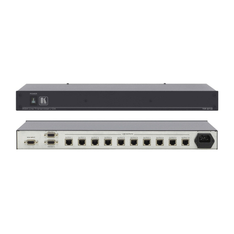
Kramer TP-410 User manual

KRAMER ELECTRONICS LTD.
USER MANUAL
MODEL:
TP-410
UXGA-Audio-RS-232 Line
Transmitter / DA
P/N: 2900
-000733 Rev 3


TP-410 – Contents i
Contents
1Introduction 1
2Getting Started 2
2.1 Achieving the Best Performance 2
3Overview 3
3.1 Shielded Twisted Pair (STP) / Unshielded Twisted Pair (UTP) 4
3.2 Defining EDID 4
3.3 Defining the TP-410 UXGA-Audio-RS-232 Line Transmitter / DA 4
4Installing in a Rack 8
5Connecting the TP-410 9
5.1 Connecting the TP-410 9
5.2 Connecting to the TP-410 via an RS-232 Connection 11
5.3 Connecting to the TP-410 via an RS-485 Connection 11
5.4 Connecting to the TP-410 via the ETHERNET 12
5.5 Connecting Several TP-410 Units 14
6Configuration and Distribution of Control Data 15
6.1 The Local Mode 15
7The SETUP DIP-switches 19
7.1 Setting the Machine Number 19
7.2 Setting the RS-232/RS-485 Baud Rate DIP-switches 20
7.3 Setting the RS-485 Bus Termination 21
8Wiring the CAT 5 LINE IN / LINE OUT RJ-45 Connectors 22
9Acquiring the EDID 23
10 Flash Memory Upgrade 24
11 Technical Specifications 25
11.1 Communication Parameters 26
12 Default EDID 27
13 Kramer Communication Protocol 2000 28
Figures
UFigure 1: TP-410 UXGA-Audio-RS-232 Line Transmitter / DA Front PanelU5
UFigure 2: TP-410 UXGA-Audio-RS-232 Line Transmitter / DA Rear PanelU6
UFigure 3: Connecting the TP-410, UXGA-Audio-RS-232 Line Transmitter / DAU10
UFigure 4: RS-232 PinoutU11
UFigure 5: Local Area Connection Properties WindowU13
UFigure 6: Internet Protocol (TCP/IP) Properties WindowU13
UFigure 7: Connecting Multiple TP-410 UnitsU14
UFigure 8: Local Control via RS-232U16
UFigure 9: Control via the EthernetU16
UFigure 10: RS-232 Remote ControlU17
UFigure 11: Connecting Multiple TP-410 Units via RS-485U18
UFigure 12: The Address # DIP-switchesU19
UFigure 13: TP-410 Baud Rate DIP-switchesU20
UFigure 14: TP-410 DIP-switch RS-485 TerminationU21
UFigure 15: CAT 5 PINOUTU22

TP-410 – Introduction 1
1 Introduction
Welcome to Kramer Electronics! Since 1981, Kramer Electronics has been
providing a world of unique, creative, and affordable solutions to the vast range of
problems that confront video, audio, presentation, and broadcasting professionals
on a daily basis. In recent years, we have redesigned and upgraded most of our
line, making the best even better!
Our 1,000-plus different models now appear in 11 groups that are clearly defined
by function: GROUP 1: Distribution Amplifiers; GROUP 2: Switchers and Routers;
GROUP 3: Control Systems; GROUP 4: Format/Standards Converters; GROUP 5:
Range Extenders and Repeaters; GROUP 6: Specialty AV Products; GROUP 7:
Scan Converters and Scalers; GROUP 8: Cables and Connectors; GROUP 9:
Room Connectivity; GROUP 10: Accessories and Rack Adapters and GROUP 11:
Sierra Video Products.
Congratulations on purchasing your Kramer TP-410 UXGA-Audio-RS-232 Line
Transmitter / DA. This product, which incorporates HDMI™ technology, is ideal for:
•Transmission of video, audio and RS-232 signals for extended distances
over standard STP/UTP cables
•Multimedia and presentation source and acceptor selection

2 TP-410 - Getting Started
2 Getting Started
We recommend that you:
•Unpack the equipment carefully and save the original box and packaging
materials for possible future shipment
•Review the contents of this user manual
•Use Kramer high performance high resolution cables
•Use only the power cord that is supplied with this machine
Go to http://www.kramerelectronics.com to check for up-to-date
user manuals, application programs, and to check if firmware
upgrades are available (where appropriate).
2.1 Achieving the Best Performance
To achieve the best performance:
•Use only good quality connection cables to avoid interference, deterioration
in signal quality due to poor matching, and elevated noise levels (often
associated with low quality cables)
•Do not secure the cables in tight bundles or roll the slack into tight coils
•Avoid interference from neighboring electrical appliances that may adversely
influence signal quality
•Position your Kramer TP-410 away from moisture, excessive sunlight and
dust
i

TP-410 – Overview 3
3 Overview
The TP-410 UXGA-Audio-RS-232 Line Transmitter / DA is a high performance,
10-channel VGA/UXGA, audio and data to CAT 5 transmitter for high resolution
video, unbalanced stereo audio (or S/PDIF digital audio) and full-duplex RS-232
signals. The CAT 5 input can also be connected to any Kramer compatible TP
transmitter (for example, the TP-125EDID) and the CAT 5 outputs can be
connected to any Kramer compatible TP receiver (for example, the TP-126).
The TP-410 can also route bidirectional data from the RS-232, RS-485 or the
Ethernet port to any or all of the CAT 5 outputs.
TP-410 features:
•VGA up to WUXGA (1920 x 1200) and 2k resolutions
•A selectable local input or twisted pair input (UXGA, audio and RS-232)
•Selectable unbalanced stereo or digital audio S/PDIF input signals
•One local output on a 15-pin HD computer graphics video connector
•One digital audio (S/PDIF) local output on an RCA connector, as well as one
analog audio local output on a 3.5mm mini jack
•10 RJ-45 STP/UTP outputs
•Compatibility with most Kramer twisted pair transmitters/receivers
•EDID (Extended Display Identification Data) that can be copied and stored
from the display device. The display can be disconnected and later
reconnected without rebooting the operating system
•A transmission range of up to 300ft (up to 100 meters) over STP cabling for
the input and outputs
•Control via front panel input select button, RS-232, RS-485 and the Ethernet
•A baud rate of up to 19,200 for sending distributed control data and
configuration commands
•Data - Extensive Bi-Directional RS-232 handling, including embedding and
de-embedding options

4 TP-410 - Overview
In addition, the TP-410:
•Can automatically differentiate between RS-232/RS-485 commands that
control the unit itself and commands that are destined for end-user
equipment (see Section 6
•Is housed in a 19” 1U rack mountable enclosure, with rack “ears” included,
and is fed from a 100-240 VAC universal switching power supply.
)
3.1 Shielded Twisted Pair (STP) / Unshielded Twisted Pair
(UTP)
We recommend that you use Shielded Twisted Pair (STP) cable, and stress that
the compliance to electromagnetic interference was tested using STP cable. There
are different levels of STP cable available, and we advise you to use the best
quality STP cable that you can afford. Our non-skew-free cable, Kramer BC-STP
is intended for analog signals where skewing is not an issue.
In cases where there is skewing, our Unshielded Twisted Pair (UTP) skew-free
cable, Kramer BC-XTP, may be advantageous, and UTP cable might also be
preferable for long range applications. In any event when using UTP cable, it is
advisable to ensure that the cable is installed far away from electric cables, motors
and so on, which are prone to create electrical interference.
3.2 Defining EDID
The Extended Display Identification Data (EDID) is a data-structure provided by a
display, to describe its capabilities to a graphics card (that is connected to the
display’s source). The EDID enables the TP-410 to “know” what kind of monitor is
connected to the output. The EDID includes the manufacturer’s name, the product
type, the timing data supported by the display, the display size, luminance data
and (for digital displays only) the pixel mapping data.
EDID is defined by a standard published by the Video Electronics Standards
Association (VESA).
3.3 Defining the TP-410 UXGA-Audio-RS-232 Line Transmitter
/ DA
This section defines the TP-410.

Figure 1: TP-410 UXGA-Audio-RS-232 Line Transmitter / DA Front Panel
#
Feature
Function
1 POWER LED Lights when the unit receives power
2 AUDIO LEDs S/PDIF Lights when a local digital audio input is selected
3 ANALOG Lights when a local analog audio input is selected
4 SOURCE LEDs TP Lights when a UXGA/Audio/RS-232 via twisted pair input is selected
5 LOCAL Lights when the local UXGA/Audio/RS-232 input is selected
6 INPUT SELECTOR
Buttons AUDIO Press to select the digital audio source or release to select the analog audio source
7 SOURCE Press to select the twisted pair source or release to select the local source
5TP-410 – Overview

TP-410 – Overview 6
Figure 2: TP-410 UXGA-Audio-RS-232 Line Transmitter / DA Rear Panel
# Feature Function
8 EDID STATUS LED Lights during normal operation; blinks when acquiring the EDID
9 CAPTURE Button Press to acquire the EDID information from the display (see Section 9
10 )
AUDIO
OUT ANALOG 3.5mm Mini
Connector Connect to an unbalanced stereo audio local acceptor to monitor any audio source
11 S/PDIF LOOP RCA Connector Connect to a digital audio local acceptor to monitor any audio source
12 AUDIO
INPUTS S/PDIF AUDIO RCA Connector Connect to the selectable digital audio source
13 ANALOG AUDIO 3.5mm Mini
Connector Connect to the selectable unbalanced stereo audio source
14 TP IN EQ. Trimmer Adjusts the cable compensation (equalization) level for the UXGA (RJ-45 TP input)
Degradation and VGA/XGA signal loss can result from using long cables (due to the effects of
stray capacitance, for example), sometimes leading to a loss of sharpness in high-resolution
signals
Use a screwdriver to carefully rotate the trimmer, adjusting the appropriate level
15 LEVEL Trimmer Adjusts the output signal level for the UXGA (RJ-45 TP input)
Use a screwdriver to carefully rotate the trimmer, adjusting the appropriate level
16 RJ-45 Connector Connect to the LINE OUT connector of a transmitter (the PINOUT is defined in Section 8
17
),
for example, the TP-125EDID
OUT 15-pin HD Connector Connect to a local display to monitor any computer graphics source
18 UXGA IN 15-pin HD Connector Connect to a computer graphics source
19 TP OUTPUTS RJ-45 Connectors Connect to the LINE IN RJ-45 connector on a receiver, for example, the TP-126 (from 1
to 10)
Using a UTP CAT 5 cable with RJ-45 connectors at both ends (the PINOUT is defined in
Section 8
20 )
RS-232 (Tx, Rx, G) Connect to the RS-232 controller (PINs 2, 3 and 5 of a standard 9-pin D-sub connector –
see Section 5.2)

#
Feature
Function
21 RS-485 (G,B,A) Connect to the RS-485 controller.
Pins B (-) and A (+) are for RS-485; connect pin G to the cable shield (if required)
22 ETHERNET Connector Connects to the PC or other Serial Controller through computer networking
23 FLASH N/A (for factory use only)
24 FACTORY RESET
Turn the machine OFF using the power switch and then turn it ON while pressing the
FACTORY RESET button. The unit will power up and load its memory with the following
factory default definitions: default Ethernet settings (IP address: 192.168.1.39; TCP port
#: 5000 and UDP port #: 50000); RS-232 data is distributed to all 10 outputs and is
received by output 1 and the default EDID is acquired
25 SETUP DIP-switches For setup of the unit (see Section 7
26 )
Power Connector with Fuse AC connector enabling power supply to the unit
27 Power Switch Switch for turning the unit ON or OFF
7TP-410 – Overview

8 TP-410 - Installing in a Rack
4 Installing in a Rack
This section provides instructions for rack mounting the unit.

TP-410 - Connecting the TP-410 9
9
5 Connecting the TP-410
This section describes how to connect:
•The TP-410 (see Section 5.1
•Several TP-410 units (see
)
Section 5.5
•To the TP-410 via RS-232 (see
)
Section 5.2
•To the TP-410 via RS-485 (see
)
Section 5.3
•To the TP-410 via the Ethernet (see
)
Section 5.4
5.1 Connecting the TP-410
)
Always switch off the power to each device before connecting it to your
TP-410. After connecting your TP-410, connect its power and then
switch on the power to each device.
To connect the TP-410, as illustrated in the example in Figure 3:
1. Connect a computer graphics source to the UXGA IN 15-pin HD connector.
2. Connect an unbalanced stereo audio source (for example, the audio source
of the computer) to the AUDIO INPUT 3.5mm mini jack connector.
You can also connect a digital audio source to the S/PDIF RCA connector and select
the desired input via the AUDIO INPUT SELECTOR (release the button to select the
analog audio and push to select the S/PDIF audio source)
3. Connect a transmitter (for example, the Kramer TP-125EDID or another
TP-410 unit) to the TP-IN CAT 5 connector.
You can connect one or both of the inputs (LOCAL and/or TP).
Press the SOURCE INPUT SELECT button to select LOCAL (UXGA
IN) or release the button to select TP.
4. Connect the OUT 15-pin HD connector to a UXGA accepter (for example, a
local display).
5. Connect the OUT unbalanced stereo audio and/or S/PDIF to unbalanced
audio and/or digital audio acceptors, respectively (not shown in Figure 3).
i
i

10 TP-410 - Connecting the TP-410
6. Connect the 10 TP OUTPUT STP/UTP connectors to up to 10 TP receivers
(for example, the TP-126 or additional TP-410 units).
7. If required, you can connect a PC and/or controller to the:
RS-232 terminal block (see Section 5.2
RS-485 terminal block (see
)
Section 5.3 and Section 6
Ethernet connector (see
)
Section 5.4
8. Set the DIP-switches (see
)
Section 7
9. Connect the power cord (not shown in
)
Figure 3).
We recommend that you use only the power cord that is supplied with this machine
Figure 3: Connecting the TP-410, UXGA-Audio-RS-232 Line Transmitter / DA
When using the TP as the source, adjust the EQ/LEVEL trimmers
immediately after turning the power ON. It is recommended to perform
this adjustment using the OUT local display.
i

TP-410 - Connecting the TP-410 11
11
5.2 Connecting to the TP-410 via an RS-232 Connection
You can operate the destination devices (for example, displays) or the TP-410 via
the RS-232 port from a distance of up to 25m (82ft) using a PC or other controller
with an RS-232 port.
To connect the RS-232 port on the TP-410 to an RS-232 device:
1. Connect the RS-232 Tx pin on the TP-410 to pin 2 (9-pin D-sub) on the
RS-232 device.
2. Connect the RS-232 Rx pin on the TP-410 to pin 3 (9-pin D-sub) on the RS-232
device.
3. Connect the RS-232 G pin on the TP-410 to pin 5 (9-pin D-sub) on the RS-232
device.
1
2
6
3
7
4
8
5GND
Tx
Rx
9
Figure 4: RS-232 Pinout
5.3 Connecting to the TP-410 via an RS-485 Connection
You can operate the destination devices (for example, displays) or the TP-410 via
the RS-485 port from a distance of up to 1000m (3000ft) using a PC or other
controller with an RS-485 port.
To connect a PC or controller to the RS-485 port on the unit:
1. Connect the pins on the following ports:
Connect the A(+) pin on the RS-485 port of the PC to the A pin on the
RS-485 port on the rear panel of the TP-410
Connect the B(–) pin on the RS-485 port of the PC to the B pin on the
RS-485 port on the rear panel of the TP-410

12 TP-410 - Connecting the TP-410
If required, connect the GND pin on the RS-485 port of the PC to the G
(ground) pin on the rear panel of the TP-410
For RS-485 communication, the ground is usually not connected between the
devices. When using a shielded cable, the shield may be grounded on one side
2. If this is the only TP-410 on the RS-485 bus, set the RS-485 termination
DIP-switch (see Section 7.3
If several units are connected via the RS-485 bus, set the termination switches on both
physical ends of the bus
) to ON (for RS-485 line termination with 120Ω).
5.4 Connecting to the TP-410 via the ETHERNET
You can connect the TP-410 via the Ethernet, using a crossover cable
(see Section 5.4.1) for direct connection to the PC or a straight through cable (see
5.4.2Section
5.4.1 Connecting the ETHERNET Port directly to a PC (Crossover Cable)
) for connection via a network hub or network router.
You can connect the Ethernet port of the TP-410 to the Ethernet port on your PC,
via a crossover cable with RJ-45 connectors.
This type of connection is recommended for identification of the
factory default IP Address of the TP-410 during the initial
configuration.
After connecting the Ethernet port, configure your PC as follows:
1. Right-click the My Network Places icon on your desktop.
2. Select Properties.
3. Right-click Local Area Connection Properties.
4. Select Properties.
The Local Area Connection Properties window appears.
5. Select the Internet Protocol (TCP/IP) and click the Properties Button (see
Figure 5).
i

TP-410 - Connecting the TP-410 13
13
Figure 5: Local Area Connection Properties Window
6. Select Use the following IP Address, and fill in the details as shown in
Figure 6.
7. Click OK.
Figure 6: Internet Protocol (TCP/IP) Properties Window
5.4.2 Connecting the ETHERNET Port via a Network Hub (Straight-Through
Cable)
You can connect the Ethernet port of the TP-410 to the Ethernet port on a network
hub or network router, via a straight-through cable with RJ-45 connectors.
5.4.3 Ethernet Port Configuration
To configure the Ethernet parameters, set DIP-switches 1 to 4 to ON (ON-ON-ON-
ON), turn the power off and then back on.

14 TP-410 - Connecting the TP-410
Use your PC initially to configure the Ethernet settings using K-UPLOAD software.
When configuration is complete, set the DIP-switches to their previous position and
then turn the power Off and On again.
The latest version of K-UPLOAD and installation instructions can be
downloaded from the Kramer Web site at www.kramerelectronics.com
5.5 Connecting Several TP-410 Units
You can daisy chain up to 15 TP-410 machines, as illustrated in Figure 7.
Figure 7: Connecting Multiple TP-410 Units
i

TP-410 - Configuration and Distribution of Control Data 15
15
6 Configuration and Distribution of Control
Data
The TP-410 distributes VGA, audio and control data signals:
•The VGA and audio signals always operate as a 1:10 distributor: the input
signal is distributed to all 10 outputs
•By default, the control data is distributed to all 10 outputs and the reply is
received from output 1
Using the TP-410 you can configure and distribute control data via the TP-410, in
the local or remote mode.
You can select the TP output/s to which the control data is distributed, as well as
the TP output for reply, using the Protocol 2000 configuration commands (see
Section 12
).
Note that Protocol 2000 commands are sent together with the
distributed control data. This applies to a single unit or multiple
cascaded units, supplying up to 150 destination control points.
6.1 The Local Mode
In the local mode, you can configure and distribute the control data via the
RS-232/RS-485 port or the Ethernet port on the TP-410 rear panel. Each
connected unit is identified by the machine number and the output to which it is
connected.
6.1.1 Connecting a PC via RS-232/RS-485
In this example, a local computer graphics source is connected to the UXGA IN
15-pin HD connector and the S/PDIF audio input of the TP-410 unit that is in the
local mode. Outputs 2 and 5 are connected to TP-126 units and output 10 is
connected to the TP IN RJ-45 connector of an additional TP-410 unit that is in the
remote mode (see Section 6.1.3). The system is controlled by a laptop via
RS-232. Each machine in this configuration is identified by its address number
and output location, as illustrated in Figure 8.
i

16 TP-410 - Configuration and Distribution of Control Data
Figure 8: Local Control via RS-232
6.1.2 Connecting a PC via the Ethernet
In this example, a computer graphics source is connected via a transmitter to the
TP IN RJ-45 connector. Outputs 1, 4 and 5 are connected to TP-126 units. The
system is controlled by a laptop via the Ethernet. The machines in this
configuration are identified by their address number and output location, as
illustrated in Figure 9.
Figure 9: Control via the Ethernet

TP-410 - Configuration and Distribution of Control Data 17
17
6.1.3 The Remote Mode
In the remote mode, the PC is connected to the RS-232 port on the transmitter (for
example, TP-125EDID). In this example, the PC controls machine # 1 and all its
outputs, as well as machine # 2 and its outputs.
Figure 10: RS-232 Remote Control
6.1.4 Connecting Multiple TP-410 Units via the RS-485 Bus
You can connect up to 15 TP-410 units via the RS-485 bus with control from a PC
or serial controller. To connect up to 15 TP-410 units via RS-485 (see Figure 11):
1. Connect the RS-485 terminal block of the first TP-410 to the RS-485
terminal block of the second TP-410, and so on (see Section 5.3
2. Set each TP-410 address number to be a unique number (see
),
connecting all the TP-410 units via the RS-485 terminal blocks.
Section 7.1
3. On the first and last TP-410 physical devices on the RS-485 bus, set the
RS-485 termination DIP-switch ON (terminating the RS-485 line at 120Ω,
see
).
Section 7.3
4. On all other TP-410 units, ensure that the RS-485 termination DIP-switch is
OFF.
).
Table of contents
Other Kramer Transmitter manuals

Kramer
Kramer WP-110 User manual

Kramer
Kramer PT-2UT/R-KIT User manual

Kramer
Kramer WP-110xl User manual

Kramer
Kramer TP-583T User manual

Kramer
Kramer SID-VGA User manual

Kramer
Kramer VP-200XLTHD User manual

Kramer
Kramer TP-551N User manual

Kramer
Kramer TOOLS TP-104 User manual

Kramer
Kramer TP-205A User manual

Kramer
Kramer WP-121 User manual

Kramer
Kramer TP-580TD User manual

Kramer
Kramer TP-15 User manual

Kramer
Kramer PT-572HDCP+ User manual

Kramer
Kramer TP-210A User manual

Kramer
Kramer 691 User manual

Kramer
Kramer PT-571 User manual

Kramer
Kramer DigiTOOLS KW-11T User manual

Kramer
Kramer WP-871xr User manual
Kramer
Kramer TP-780T User manual

Kramer
Kramer DIP-20 User manual