Allied 11K50 User manual

507369-03 Issue 1737 Page 1 of 4
Save these instructions for future reference
INSTALLATION INSTRUCTIONS
Gas Changeover Kit
Natural to Regulated LP/Propane (Kit #11K50)
For A80, 80G1, A93, A95, 92G1, 95G1 and 96G1 Units
Manufactured By
Allied Air Enterprises LLC
A Lennox International, Inc. Company
215 Metropolitan Drive
West Columbia, SC 29170
This manual must be left with the homeowner for future reference.
(P) 507369-03
*P507369-03*
WARNING
In the U.S., this conversion kit is to be installed by a licensed professional service technician (or equivalent) or other
qualied agency in accordance with the manufacturer’s instructions and all codes and requirements of the authority having
jurisdiction. If the information in these instructions is not followed exactly, a re, an explosion, or production of carbon
monoxide may result, causing property damage, personal injury or loss of life. The qualied agency is responsible for the
proper installation of the kit. The installation is not proper and complete until the operation of the converted furnace is
checked as specied in the furnace manufacturer’s instructions supplied with the kit.
Shipping and Packing List
Package 1 of 1 contains:
12 -Main burner orices (0.034)
1 - Gas converter sticker
1 - Nameplate conversion sticker
1 - Bag assembly containing:
1- Gas valve regulator spring
1- Low gas inlet pressure switch
1- Gas valve inlet brass tting
1- Wiring harness
Check the kit for shipping damage. If you nd any damage,
immediately contact the last carrier.
Application
Use natural to LP/Propane gas conversion kit 11K50 to
convert units from natural gas to LP/Propane.
Installation
CAUTION
As with any mechanical equipment, personal injury can
result from contact with sharp sheet metal edges. Be
careful when you handle this equipment.
CAUTION
Gas valve conversion kit MUST be installed BEFORE
the unit is red using LP/propane gas. Unit damage
WILL OCCUR if the unit is red using LP/propane gas
with the original natural gas orices.
1. Set the thermostat to the lowest setting. If the gas
supply line has been connected, shut off the gas
supply to the furnace, then disconnect the electrical
power.

507369-03Issue 1737Page 2 of 4
2. Remove the heating compartment access panel. Turn
the automatic gas valve switch to the OFF position.
See Figure 2 and Figure 3.
3. Disconnect the gas supply and the two wires at the
gas valve.
4. Remove the burner box cover (if equipped). Remove
the four manifold securing screws. Slide the manifold/
gas valve assembly out of the burner box.
5. Replace the burner orices with the provided gas
orices. Torque to approximately 35 in-lbs. Do not
use sealant on orices. Figure 4 and Figure 5 show
manifold/gas valve assembly.
IMPORTANT
DO NOT use pipe dope or any pipe sealant on gas orice
threads.
6. Replace the gas valve regulator spring with the
provided regulator spring. See Figure 6.
7. A80 and 80G1 units with Nox inserts being converted
from natural to LP /Propane.
a. Remove the burner box assembly from the
vestibule panel.
b. Remove the screws which secure each of the
NOx inserts to the clamshell. Remove the NOx
inserts and reinstall the screws. See Figure 1.
c. Re-install burner box assembly.
NOx Insert
Re-install Screws
Figure 1. NOx Inserts
8. Re-install the manifold/valve assembly.
9. Thread provided brass tting to gas valve inlet until
hand tight. Using properly sized wrench, tighten tting
2 to 3 full turns being careful to position the side port to
allow clearance for the pressure switch and harness.
See Figure 2.
NOTE: Never use channel lock pliers or a pipe wrench
on the brass tting.
NOTE: Some installations may require the pressure
switch and tting assembly to be positioned differently
than shown in Figure 2.
10. Thread the gas supply to the brass tting until hand
tight. Using properly sized wrench to support brass
tting, tighten supply line into tting 2 to 3 full turns to
achieve leak free joint.
NOTE: Do not over tighten. (Maximum 3 full turns past
hand tight for ½” NPT per ASME B1.20.1-2013)
11. Thread pressure switch to brass tting 2 to 3 turns
past hand tight, then wire as shown in Figure 7.
12. Restore the electrical power to the unit.
13. Inspect all sides of assembly. Turn on gas supply.
Immediately check the entire tting surface and
assembly joints for gas leaks.
14. Afx nameplate conversion sticker next to unit
nameplate.
15. Complete the information required on the gas converter
sticker: date, name, and address. Afx sticker to the
exterior of the unit in a visible area.
16. Follow the steps given in the start-up and adjustment
section.
IMPORTANT
Carefully check all piping connection for gas leaks. DO
NOT use matches, candles, open ames or other means
of ignition to check for gas leaks. Use a soap solution or
other preferred means.
CAUTION
Some soaps used for leak detection are corrosive to
certain metals. Carefully rinse piping thoroughly after
leak test has been completed. Do not use matches,
candles, ame or other sources of ignition to check for
gas leaks.
Brass Fitting
Low Inlet Pressure Switch
Figure 2. Gas Valve with Low Inlet Pressure Switch
Location

507369-03 Issue 1737 Page 3 of 4
NEGATIVE BARBED FITTING
(remove for manifold adjustment)SURE OUTLET
GAS VALVE SHOWN IN ON POSITION
MANIFOLD PRES-
Figure 3. Gas Valve
Gas Valve
Sensor
Manifold
and Orifices
Burners
Figure 4. Manifold Gas Valve Assembly
(A93, A95, 92G1, 95G1 & 96G1)
Gas Valve
Ignitor
Manifold and
Orifices
Sensor
Figure 5. Manifold Gas Valve Assembly
(A80 & 80G1)
tor adjusting screw.
2. Remove the existing spring.
3. Insert the replacement spring.
4. Install the new plastic pressure regulator adjustment screw so
that
tor. Turn the pressure regulator adjusting screw clockwise six
sure
tor.
5. Check the regulator setting
ing the gas meter.
6. Re-install the barbed fiting.
Inlet Pressure
Tap
Pressure Regulator
Adjusting Screw
Spring
(LP Spring will be red)
Gas Inlet
Barbed Fitting
(if equipped)
Figure 6. Conversion of Gas Valve
GAS VALVE
NO
C
WHITE
ORANGE
LOW INLET
PRESSURE
SWITCH
YELLOW
ORANGE
PROVIDED HARNESS WIRES
MV
MV
Figure 7. Low Inlet Pressure Switch Wiring
Point-to-Point Wiring Diagram
Start-Up & Adjustment
BEFORE LIGHTING - Smell all around the appliance area
for gas. Be sure to smell next to the oor because LP/
Propane gas is heavier than air and will settle on the oor.
Use only your hand to move the gas control switch. Never
use tools. If the switch will not move by hand, do not try to
repair it. Force or attempted repair may result in a re or
explosion.

507369-03Issue 1737Page 4 of 4
Placing the Unit into Operation
IMPORTANT
Follow the lighting instructions provided on the unit.
If lighting instructions are not available, refer to the
following section.
Units are equipped with a hot surface ignition system. The
ignition system automatically lights the burners each time
the thermostat calls for heat.
1. STOP! Read the safety information at the beginning
of this section.
2. Set the thermostat to its lowest setting.
3. Turn off all electrical power to the furnace.
4. Do not try to light the burners by hand.
5. Remove the unit access panel.
6. Move gas valve switch to OFF. See Figure 3.
7. Wait ve (5) minutes for any gas to clear out. If you
then smell gas, STOP! Immediately call your gas
supplier from a neighbor’s phone. Follow the gas
supplier’s instructions. If you do not smell gas, go to
the next step.
8. Move gas valve switch to ON. See Figure 3.
9. Replace the unit access panel.
10. Turn on all electrical power to the unit.
11. Set the thermostat to desired setting.
12. If the furnace will not operate, see the section “Turning
Gas Off to the Unit” and call your the gas supplier.
Gas Pressure Measurement
Gas Flow (Approximate)
Capacity
Seconds for One Revolution
Natural LP
1 cu ft
Dial
2 cu ft
Dial
1 cu ft
Dial
2 cu ft
Dial
-045 80 160 200 400
-070 55 110 136 272
-090 41 82 102 204
-110 33 66 82 164
-135 27 54 68 136
Natural - 1000 btu/cu ft LP - 2500 btu/cu ft
Table 1. Gas Meter Clocking Chart
Furnace should operate at least 5 minutes before checking
gas ow. Determine time in seconds for two revolutions of
gas through the meter. (Two revolutions assures a more
accurate time.) Divide by two and compare to time in
Table 1. If manifold pressure matches Table 2 and rate is
incorrect, check gas orices for proper size and restriction.
Remove temporary gas meter if installed.
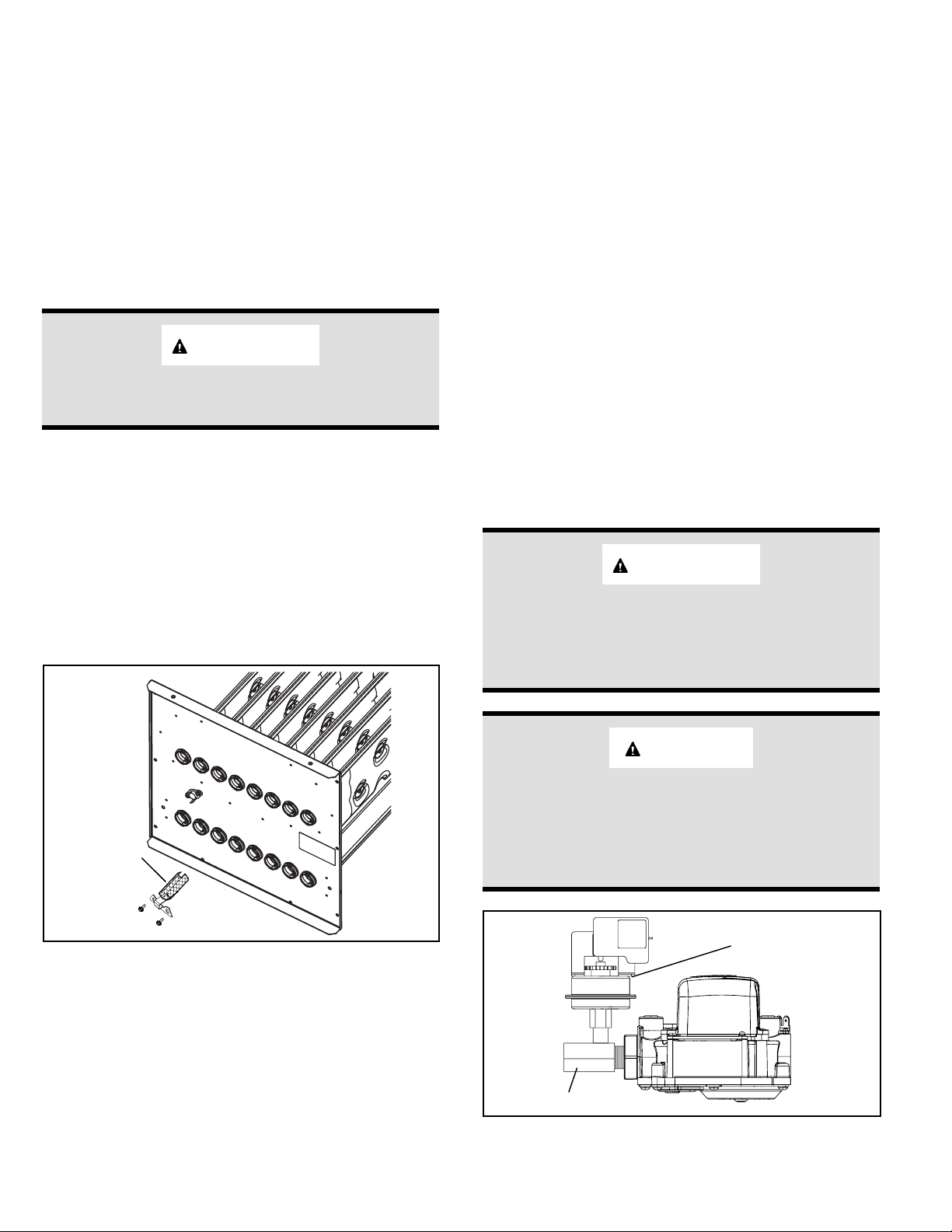
Supply Pressure Measurement
When testing supply gas pressure, use the 1/8” N.P.T.
supply line tap located on the gas valve to facilitate test
gauge connection. See Figure 2. Check gas line pressure
with unit ring at maximum rate. Low pressure may result
in erratic operation or underre. High pressure can result in
permanent damage to gas valve or overre.
On multiple unit installations, each unit should be checked
separately, with and without units operating. Supply
pressure must fall within range listed in Table 2.
NOTE: To obtain accurate reading, shut off all other gas
appliances connected to meter.
Manifold Pressure Measurement
1. Connect test gauge to manifold pressure tap (Figure
2) on gas valve.
2. Start unit and allow 5 minutes for unit to reach steady
state.
3. After allowing unit to stabilize for 5 minutes, record
manifold pressure and compare to value given in
Table 2.
4. If necessary, make adjustments. Figure 2 shows
location of adjustment screw.
Capacity
Manifold
Pressure in. w.g.
0 - 7500 ft.
Supply Line Pressure
in. w.g.
Min Max
All Models 10.0 11.0 13.0
Table 2.
Proper Combustion
Furnace should operate minimum 15 minutes with correct
manifold pressure and gas ow rate before checking
combustion. Take combustion sample beyond the ue
outlet and compare to Table 3.
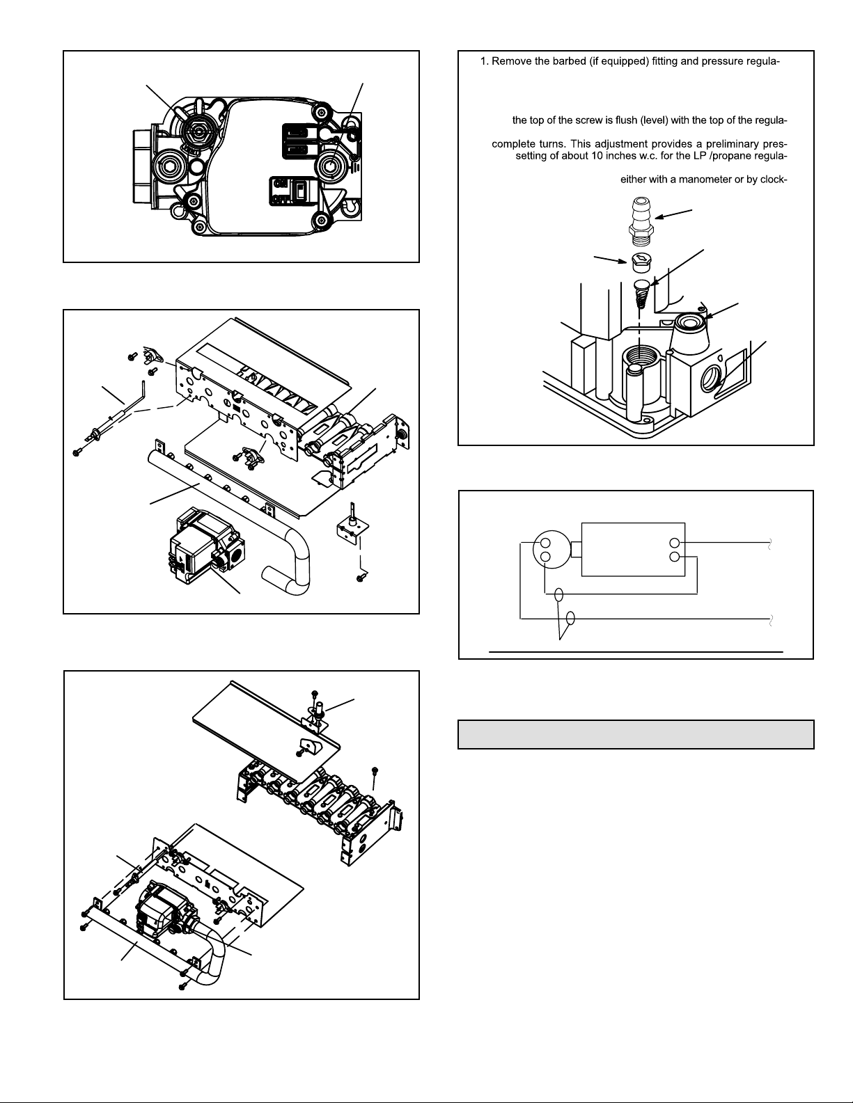
NOTE: Shut unit off and remove manometer as soon as
the supply pressure, manifold pressure and combustion
sample have been obtained. Take care to remove barbed
tting and replace threaded plug.
Model CO2% for LP
All A93, A95, 92G1, 95G1 &
96G1 Units 8.4 - 9.6
All A80 & 80G1 Units 7.5 - 9.0
The carbon monoxide reading should not exceed 100 ppm.
Table 3.
Turning Off Gas to the Unit
1. Set the thermostat to its lowest setting.
2. Turn off all the electrical power to the unit.
3. Remove the access panel.
4. Move the switch on the gas valve to OFF. Do not force
the switch.