ALLNIC AUDIO D-10000 User manual

D-10000
DIGITAL TO ANALOG CONVERTER
OUTPUT TRANSFORMER-LESS / OUTPUT CAPACITOR-LESS
OWNERS MANUAL

Allnic Audio
D-10000 OTL/OCL
Digital to Analog Converter
Thank you for purchasing this Allnic Audio D-10000 OTL/OCL Digital to
Analog Converter (DAC). We are certain your trust in Allnic Audio and
Audiomentors, as well as your appreciation for the sound of this
innovative and ground-breaking device, will be rewarded by its excellent
operation for many years to come.
Please read this entire manual before you connect the D-10000 OTL/OCL
to the other components of your system and the electrical receptacle.
Audiomentors (Allnic Audio marketing company)
415, Daeduck Plaza
19-4 Sunae-dong, Bundang-gu,
Seongnam-si, Gyeonggi-do,
13595 S.Korea
Direct Telephone: 0082-31-716-3311
email: audiomentors@naver.com
Website: www.audiomentors.co.kr
** Information and specifications for the Allnic Audio product
described in this manual are subject to change without notice

TABLE OF CONTENTS:
INTRODUCING THE D-10000 OTL/OCL
DIGITAL TO ANALOG CONVERTER
1
WHAT’S IN THE BOX?
3
SAFETY
4
CLEANING
Chassis
Connectors
4
INITIAL SET-UP
Location, Location, Location
Power Connection
Inputs
Outputs
External Clock Connection
4
4
5
5
5
6
INITIAL POWER ON
6
OPERATION
DSD Playback and “CONV” (Conversion to DSD)
PCM Playback and UPSAMPLE
The Remote Control
The Balance Meters
Tubes
6
7
7
8
9
9
SPECIFICATIONS
10
WARRANTY
11
FIGURES
12
Please read about SAFETY before you attempt to use the D-10000
OTL/OCL DAC - we care about our customers and the equipment, and
we want you to enjoy this product for a long time!

1
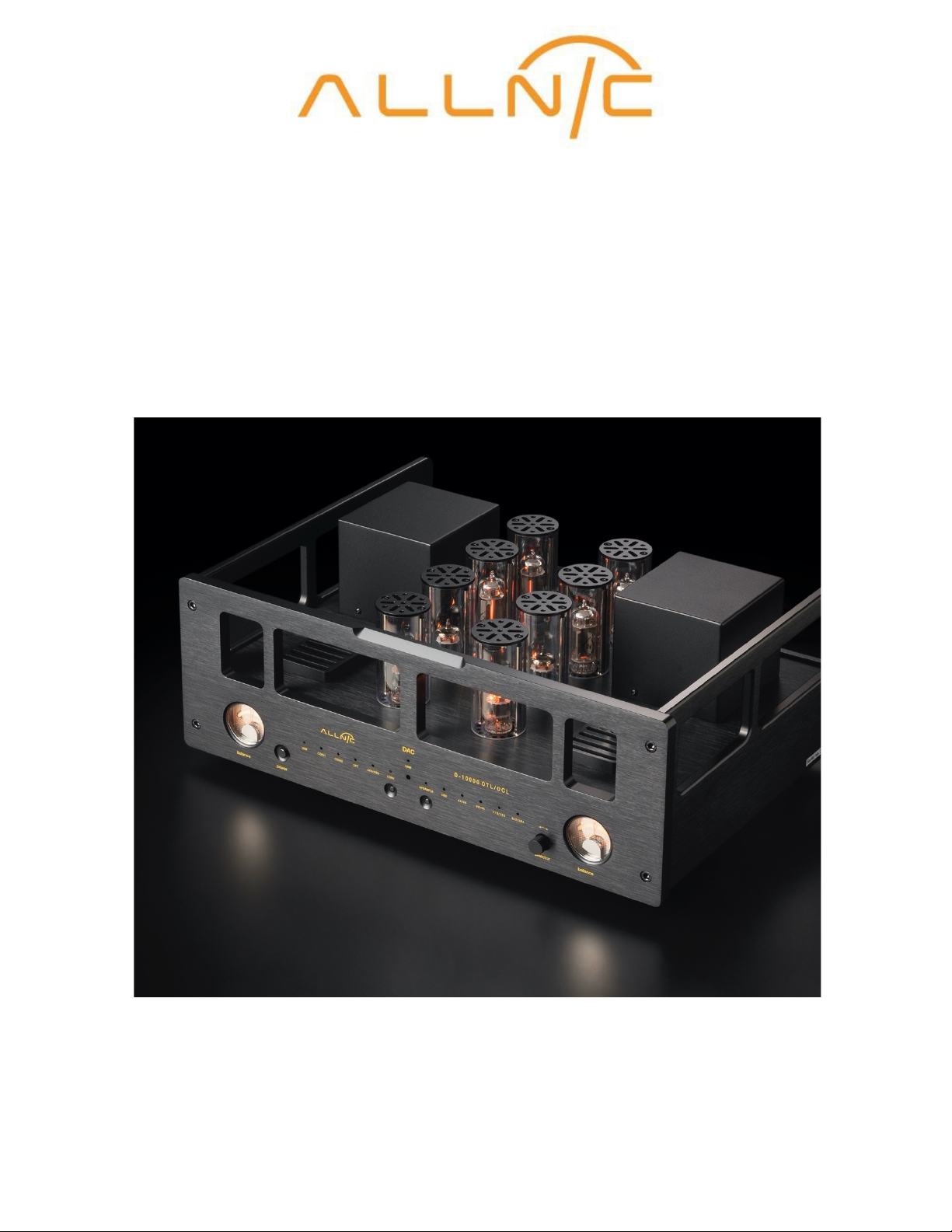
ALLNIC AUDIO D-10000 OTL/OCL DAC, ANALOG OUTPUT SIGNAL PATH
_________________________________________________________________________________
The D-10000 OTL/OCL (Output Transformer-Less/Output Capacitor-Less) DAC has a pure triple gain
stage analog signal path. It uses the 6C19P low internal resistance tube to pass the analog signal
directly to line-stage or integrated amplifiers.
In common circuits, output capacitors or output transformers are required to separate the AC music
signal from the DC operating potential. If this is not done, the latter will destroy the power amplifier,
the loudspeakers, or both. However, these two coupling devices also introduce their own influences
on the transmission of the musical signal, adding their own character (colouration), increasing
distortion, and consuming small signals, all as predicted by physical efficiency theory. In addition, they
also limit signal dynamics. For these reasons, the elimination of output transformers and capacitors
has been considered the best solution for the design of the most accurate amplifiers. Removal of these
two coupling devices from the signal path achieves the best results possible:
• No colouration of the musical signal
• Extremely detailed expression, natural harmonics and subtle musical decay
• The lowest possible distortion
• The widest musical dynamics and frequency range
In the D-10000, there is no coupling device between the DAC and the preamplifier; that is, the final
gain/output tubes are directly connected to the preamplifier. Thus, the benefits listed above are fully
present in the Allnic D-10000 OTL/OCL.
Some circuit experts might be concerned about DC potential in the music signal in an OTL/OCL design.
However, the chance of this problem occurring can be essentially and reliably 100% mitigated. To do
this, Allnic uses a “floating power supply circuit”, a design that deals with the issue by not creating any
DC potential in the first place, or such a small potential that it is harmless.
The D-10000’s OTL/OCL circuit is basically SEPP, “Single-Ended, Push-Pull”, so a “cancellation circuit” is
required to adjust the balance of signal between the upper and lower power output tubes’ input grids.
Allnic uses an extremely sophisticated “Active Balanced Positive and Negative Feedback Circuit”, in
which the 7258 pentode perfectly controls the circuit’s operation with extremely low distortion and
incredible speed.
The D-10000 OTL/OCL is a world-class, reference level, DAC. It offers unbelievably realistic, holographic
sound-staging combined with incredible resolution, clarity, micro-dynamics, and drive. Instrument and
vocal tones and timbres are breathtakingly lifelike, and the placement of instruments and bodies in
three dimensions startling, life-size, and addictive. The D-10000 OTL/OCL has no voice of its own, none.
It is silent, except for the music emanating from the blackest of backgrounds. In addition, the
stunningly realistic sonic quality is matched by the simple elegance, flexibility, and ergonomic
functionality of the D-10000 OTL/OCL’s casework and connection options. The D-10000 OTL/OCL is
truly a masterpiece and is Allnic Audio’s top DAC.

2
_______________________________
WAVERSA SYSTEMS CUSTOM DIGITAL PROCESSING
With a digital section designed by Dr. C. Shin, principal of WAVERSA SYSTEMS and an expert in high-
resolution digital and digital to analog design for both military and commercial applications, the D-
10000 OTL/OCL DAC is unique in the marketplace. Except for the DAC chip it employs, the ES9018K2M
SABRE 32 Reference DAC (“Sabre DAC”), none of the D-10000 OTL/OCL DAC’s digital components are
sourced from the audio supply market. In addition, the USB interface and SPDIF receiver are
specifically customized for use in the D-10000 OTL/OCL, and custom-built high end up-samplers are
utilized for user selectable DSD conversion and PCM up-sampling.
The D-10000 OTL/OCL offers the listener the flexibility to select listening directly to:
• the source drive’s audio signal at its native sampling rate, or down-sampled if that signal is
above the limits of the D-10000 OTL/OCL’s digital inputs, 384 KHz (so long as the source is
of sufficiently high quality – see “Operation”);
• a PCM signal from the source drive converted to DSD 128 in “real time”; or
• a PCM signal up-sampled from the source drive’s native rate by a custom up-sampling chip.
The ES9018K2M SABRE 32 Reference DAC is a high performance 32-bit, 2-channel audio D/A converter
with sampling to 32/384 KHz, DSD 128 and a 1.5 MHz up-sampler using a field programmable gate
array (“FPGA”) USB interface. In the D-10000 OTL/OCL, however, the Sabre DAC chip is used for digital
to analog conversion only; all audio signal processing is performed by a Waversa Systems custom
designed processing chip set.
The D-10000 OTL/OCL converts PCM to DSD in real-time when CONV (“Conversion”) is selected using
the D-10000 OTL/OCL’s chassis face or remote control. When conversion to DSD is selected, all PCM
input samples are converted to 128 DSD via a custom built internal 5.6 MHz up-sampler and FPGA
DSD converter.
The D-10000 OTL/OCL up-samples PCM when UPSAMPLE is selected using the D-10000 OTL/OCL’s
chassis face or remote control. When up-sampling is selected, all PCM input samples are up-sampled
using Waversa Systems’ custom built 1.5 MHz audio signal processing chip, which also then down-
samples to the selected sampling rate prior to sending to the Sabre DAC for digital to analog
conversion.
The USB interface is implemented through network player hardware by Waversa Systems and is UAC2
standard compliant. This provides an extremely clean digital audio signal through complete galvanic
isolation, which strips the digital signal of any PC noise commonly created by a server’s internal power
supply. Firmware updates and music data are also communicated through the single provided USB
input. This is accomplished by a special interface, again unique to Waversa Systems.

3
Data under-run or over-run and, therefore, distortion can occur when a source’s word clock and a
DAC’s internal word clock are not synchronized absolutely. When an external clock is used, potential
errors caused by data under-run or over-run inside a DAC can be eliminated. The D-10000 OTL/OCL
provides connections for an external word clock. In addition, it is planned to update the D-10000
OTL/OCL’s current high-end internal word clock implementation to an even more highly advanced
mode in the next update phase, currently planned for within a few months of initial release of the D-
10000 OTL/OCL DAC.
It is also intended to provide an I2S input in the near future. This separate system will be connected
to the D-10000 OTL/OCL DAC by a proprietary method through the AES port. The I2S system will
provide not only PCM but also DSD and have the capability to support extreme up-sampling and cross
conversion between DSD and PCM. Details will be published at a future date.
_______________________________
WHAT IS IN THE BOX?
Please check that the shipping box contains the following:
• One (1) Allnic D-10000 OTL/OCL DAC – in natural aluminum or black, depending on your
order specification
• One (1) Apple remote control
• One (1) Owner’s Manual
Note:
1) The D-10000 OTL/OCL DAC ships with the tubes installed.
2) The D-10000 OTL/OCL will work with most IEC type aftermarket power cords. Of course, only
you can determine the power cord that works most synergistically with the D-10000 OTL/OCL
in your system.
3) Be sure the D-10000 OTL/OCL DAC is labeled for the AC voltage of your location. If it is not,
please contact Audiomentors.
We advise that you keep the box and other packing materials that your D-10000 OTL/OCL DAC
came in. They will be useful if you sell your D-10000 OTL/OCL, or in the unlikely event you need to
ship the unit for service.
!!
!

4
SAFETY!!
• Disconnect power cords by pulling the plug, not the cable.
• Do not attempt any repairs. Do not remove the unit’s chassis cover without specific authorization
from Audiomentors.
• Keep all cables away from heat sources.
• Ensure there is plenty of free space around and above the unit.
• Keep the unit away from liquids – do not allow any liquid to enter the interior of the unit.
• When the unit is moved from a cold to a warm environment, allow sufficient time for any
condensation to evaporate before plugging the D-10000 OTL/OCL into an AC connection.
• See the notes on “Location, Location, Location”.
CLEANING
A. Chassis
Use only a soft, lint-free cloth dampened slightly with water only (NO cleaning fluids!) to clean the
faceplate and chassis of the D-10000 OTL/OCL DAC.
B. Connectors
You may use any good quality contact cleaner recommended for such applications to clean the
contacts from time to time, as you deem appropriate.
INITIAL SET-UP
A. LOCATION, LOCATION, LOCATION
Like all audio products using tubes, the Allnic Audio D-10000 OTL/OCL needs to be placed on a solid
base that is not subject to vibration or sudden shock, and that provides good air circulation around,
above and below the unit.
• DO NOT cover the top of the D-10000 OTL/OCL tube chimneys.
• DO NOT drop the unit! For those who may want to place the D-10000 OTL/OCL on some kind
of aftermarket isolation feet or similar devices, dropping one side of D-10000 OTL/OCL, or the
whole unit may result in damage to the unit or tubes that will not be covered by warranty.
• DO NOT place the unit near a strong light or heat.
• DO NOT place anything heavy on the unit.
• DO NOT allow rubber or vinyl materials to rest on the unit’s chassis for long periods of time.
This could discolour the metal.
• DO place the unit on a shelf or stand that is stable and not subject to vibration or sudden shock.

5
• DO consider using a high-quality power cord, as well as inter-connects for both inputs and
outputs. The D-10000 OTL/OCL is a highly sensitive piece of electronic designed for neutrality
and will output what you put into it.
• DO try to place the D-10000 OTL/OCL well away from major sources of RFI and EMI; though
well shielded, the D-10000 OTL/OCL will function best away from large power transformers
and other sources of such interference.
B. POWER CONNECTION
The D-10000 OTL/OCL DAC uses a standard three prong male IEC connection for AC input on the
right hand of the rear of the unit’s chassis. You need a power cord with a female three prong IEC
connector at one end (See Figure 1).
The D-10000 OTL/OCL will be set internally for your location’s electrical system characteristics.
Please check the setting for electrical input on the label on the rear of the unit to confirm that
your D-10000 OTL/OCL matches your location’s electrical system. For North American customers,
the D-10000 OTL/OCL is set internally for AC 110/120 volt – 50/60 Hz. For customers in other
regions, the unit is set for 230/240V – 50/60 Hz operation. There is no way to change to another
AC setting.
C. INPUTS
The D-10000 OTL/OCL DAC has the following inputs (See Figure 1):
• One optical (“Toslink”) digital
• One USB (Type B)
• One AES/EBU digital
• Two (2) coaxial digital (RCA)
The inputs may all be connected at the same time. To select the input you want to play, rotate the
knob on the right of the D-10000 OTL/OCL’s front panel clockwise and counter-clockwise (See Figure
2), or use the appropriate part of the remote control (See the section “The Remote Control” below).
The D-10000 OTL/OCL utilizes a non-PLL digital receiver for lower noise. To avoid introduction of noise
and/or connectivity issues, the user should be sure to use high quality digital sources and cables that
meet applicable standards for the selected input (e.g., AES/EBU, S/PDIF).
D. OUTPUTS
The D-10000 OTL/OCL is equipped with one pair of unbalanced or “single-ended” (RCA) outputs and
one pair of true balanced (XLR) output connections. Each output pair is oriented horizontally. WHEN
FACING THE REAR OF THE DAC (See Figure 1), the:
• XLR and RCA output connections are to the left of the IEC power connection;

6
• each RCA (unbalanced) connector is to the left of the XLR (balanced) connector for that
channel; and
• the left channel output connectors are to the right of the right channel connectors.
The left channel output connectors are labeled “L”, and the right channel output connectors are
labeled “R”.
You may have both balanced and unbalanced outputs connected at the same time without introducing
hum.
E. EXTERNAL CLOCK CONNECTION
The D-10000 OTL/OCL is equipped with BNC type in and out reference word clock connectors for use
with an external clock (See Figure 1).
INITIAL POWER-ON
Once you have your D-10000 OTL/OCL DAC in place, connected it to the electrical source, and all
connections have been made to your digital sources and preamplifier, you are ready to turn on
the power for your D-10000 OTL/OCL.
Before you power up the D-10000 OTL/OCL, though, be sure you have:
• checked that all your connections are snug
• selected the output connections that you want to use, single ended (RCA) or balanced (XLR), on
the switch on the back of the DAC
• turned the volume down or muted your preamplifier
To turn on the D-10000 OTL/OCL, press in the rocker switch on the left side panel near the front of
the unit and marked with on and off icons. To turn on the D-10000 OTL/OCL, press the top of the
rocker switch in. Of course, the “Off” position is the reverse, pressing the bottom of the rocker switch
in.
OPERATION
When the D-10000 OTL/OCL DAC is powered on, the balance meters on the left and right of the
front panel will illuminate (See Figure 2). When the D-10000 OTL/OCL is connected to a powered-
on source and the appropriate input for that source is selected, the LED in the top centre of the
front panel, labeled “Link”, will illuminate. Note: In some cases, the “Link” LED might not
illuminate until signal is passing from the source.

7
The USB input accommodates:
• DSD 64, DSD 128
• PCM 44.1 KHz, 48 KHz, 88.2 KHz, 96 KHz, 176.4 KHz, 192 KHz, 352.8 and 384 KHz.
Please note that the digital inputs and the customized S/PDIF receiver accommodate rates up to
192 KHz (so long as the source is of sufficiently high quality). However, because it utilizes a non-
PLL digital receiver for lower noise, users may find occasionally that some signals over 96 KHz
may be problematic, particularly with the optical/Toslink input. Users may mitigate this problem
with appropriate down-sampling at the source.
From this point on, operation is straight-forward. All functions can be accessed from the front panel.
The button “in” position makes the selected function “active”, and the associated LED/LEDs will
illuminate. The button “out” position means the function is inactive; the associated LEDs will not be
illuminated. The desired input is selected by rotating the knob on the right of the D-10000 OTL/OCL’s
front panel clockwise and counter-clockwise, or by using the appropriate part of the remote control
(See the section “The Remote Control” below).
DSD Playback and “CONV” (Conversion to DSD)
In the case of playback of a native DSD signal from the source, the D-10000 OTL/OCL employs DSD
over PCM (“DOP”). The user should set up the source software to output for the DOP standard.
Whenever the D-10000 OTL/OCL is used to playback DSD files, the DSD LED indicator will illuminate,
as well as the LED indicator for one or the other of the 176/192 or 352/384 sample rates, indicating
the DSD rate. The 176/192 indicator means the input signal is DSD 64, and the 352/384 indicator
means the input signal is DSD 128. During playback of a native DSD signal from the source, the "CONV"
and "UPSAMPLE" buttons are not used.
The button labelled “CONV” is used to implement real-time conversion to DSD. The LED indicator for
CONV illuminates when CONV is selected (this will occur even when playing a DSD file and CONV is
selected; however, in that case, no conversion is occurring). You may notice that gain in the DSD
conversion mode is slightly lower than that in the source input sample rate and upsampling modes.
This is normal and is compensated for by adjusting your volume control.
Please note that the DSD indicator light has two meanings; it indicates either that the D-10000
OTL/OCL is playing a native DSD signal from the source, OR that conversion to DSD has been selected
by the user.
PCM Playback and UPSAMPLE
When the D-10000 OTL/OCL is playing a PCM signal from source, the appropriate LED indicator for the
source sample rate will illuminate.
Please note that some high sample rate PCM signals may carry background white noise in addition to
the audio; this is because many freely distributed high resolution PCM files are generated using either

8
a software or hardware up-sampler that is not of sufficiently high quality. It is recommended that, if
possible, the source software or device is used to down-sample such signals to improve the sound
quality.
Please also note that while the D-10000 OTL/OCL filters incoming low quality SPDIF interface signals,
some source devices in the market do not meet S/PDIF standard or are otherwise of insufficient
quality and can be noisy.
The button labelled “UPSAMPLE” is used to select the desired up-sampling rate. Repeated presses of
the UPSAMPLE button move the unit through the available up-sampling rates as indicated on the front
panel.
NOTE: The user cannot control the up-sample rate for conversion to DSD; the D-10000 OTL/OCL’s
conversion to DSD and PCM “UPSAMPLE” functions are discrete processes.
Drivers are not required for Mac/Linux operating systems. The Thesycon driver is compatible for
Windows applications and is available on-line. It is currently planned to have a Windows compatible
driver that will specifically recognize the D-10000 OTL/OCL DAC available for download from the
Audiomentors and Allnic Audio websites.
Of course, BE CAREFUL about differences in gain between your sources. Generally, DACs and digital
disc players (and tuners) will have greater gain than phono-stages. That means the volume setting for
listening to your turntable might be too high for listening to a digital source through the D-10000.
When you are finished listening, turn off your power amplifier(s); then turn off your preamplifier and
then turn off your sources last, including the D-10000 OTL/OCL by pressing in the bottom of the on/off
rocker switch, located on the left side panel near the front of the unit.
NOTE: While the D-10000 OTL/OCL DAC is run in and tested at the factory, users have reported that
the sound improves steadily through the first two to three hundred hours of use.
In the case of any failure, please contact your Allnic dealer for assistance.
THE REMOTE CONTROL
The remote control allows remote operation of all the functions on the front panel of the D-10000
OTL/OCL. It does not support the on/off function, however. The remote control provided is a standard
Apple product. All functions controllable by the remote are manipulated by using the large button at
the top of the remote control, which is surrounded by a black ring with a white dot at its top and
bottom and left and right sides.
The DAC functions are selected as follows (See Figure 3, below):
• Pressing the upper part of the black main button ring selects the various inputs from right to
left on the face of the unit

9
• Pressing the lower part of the black main button ring selects the various inputs from left to
right on the face of the unit
• Pressing the right side of the black main button ring toggles CONV, conversion to DSD, on and
off, i.e., between conversion to DSD and a source’s incoming sample rate, or one of the up-
sampling rates (the latter only if you were previously in up-sampling)
• Pressing the silver central “enter” button toggles UPSAMPLE on and off and when on, cycles
through the various up-sampling rates
The remote control’s “left” side of the black main button ring, the “Menu” and the “Play/Pause”
buttons have no functions for the D-10000 OTL/OCL DAC.
If you are using an Apple device as a source or controller, or have any other Apple device nearby, it
may also respond to the D-10000 remote control. If you need to use an Apple device at the same time
as you are using the D-10000 OTL/OCL and cannot move your Apple device out of range of the D-
10000 remote control, you should be able to disable the remote control sensor of the Apple device in
the device’s System Preferences. Instructions for doing this are available on-line.
THE BALANCE METERS
The illuminated meters on the D-10000 OTL/OCL’s front panel indicate the DC balance status of the
6C19P output tubes for each channel. The needle of each meter should be at the center of the meter.
If one needle is, or both needles are, off-centered, please adjust the potentiometers located on the
top panel between two of the 6C19P output tubes. If a meter will not balance, please contact your
Allnic dealer for assistance.
TUBES
There is a set of four (4) tubes for each channel, with the right and left channels each arranged in a
row from front to rear. The D-10000 OTL/OCL uses the following tubes:
• Two (2) x 7258 (the tubes closest to the front of the DAC)
• Two (2) x 12AU7 (the tubes second from the front, i.e., between the 7258 and 6C19P tubes)
• Four (4) x 6C19P (the four tubes closest to the rear of the DAC)
All consequences of changing or attempting to change tubes are borne by the user unless by express
agreement between the owner and the Allnic dealer. The Allnic dealer, Allnic Audio and Audiomentors
are not liable in any way whatsoever for any injury or loss incurred by the user or for damage to the
D-10000 OTL/OCL, any of its parts, or tubes or replacement tubes resulting from the user changing or
attempting to change tubes.

10
SPECIFICATIONS FOR THE ALLNIC AUDIO D-10000 OTL/OCL DAC!
!
Inputs:
• One (1) X optical (“Toslink”) digital
• One (1) X USB
• One (1) X AES/EBU digital (XLR)
• Two (2) X coaxial digital (RCA)
Outputs:
• One (1) pair X unbalanced (RCA)
• One (1) pair X balanced (XLR)
Output Frequency Range:
• 20Hz - 20KHz flat
Output RMS Voltage:
• 4 volts
Output Impedance:
• 50 Ω (Constant)
Total Harmonic Distortion (THD):
• Less than 0.1%
Signal to Noise (S/N) Ratio:
• - 86db (CCIR, 1KHz)
Power Consumption:
• 70W at 230 V / 110/120 V / 50 / 60 Hz
Fuse:
• AC 3A, 250V for 110/120 volt regions
• AC 2A, 250V for 230/240 volt regions
Dimensions:
• 430mm (16.93 inches) x 320mm (12.5 inches) x 170mm (6.7 inches) (W x D x H)
Weight:
• 13.06 Kg (28 lbs.) unpacked
• 17 Kg (37.4 lbs.) in original packing

11
WARRANTY!
!
All Allnic Audio amplifier products are warranted against materials and manufacturing defects for
parts, excluding tubes, and labour for two (2) years from date of purchase. Tubes are warranted
against materials and manufacturing defects for one (1) year from date of purchase. The warranty is
transferable for the balance of the original purchaser’s warranty period, provided, as stated below, no
unauthorized repairs or modifications have been performed on the product. Date of purchase is the
date indicated on the invoice for the product issued by your authorized Allnic Audio dealer.
For the warranty to be valid, a defective product must be returned to your authorized Allnic Audio
dealer for service prior to any unauthorized attempt to repair. Any repair work on an Allnic Audio
product not expressly and specifically authorized by your authorized Allnic Audio dealer will void the
warranty on the product.!
! !

12
FIGURES
Figure 1: Rear View
Figure 2: Front View

13
Figure 3: Remote Control
!
!
S
elect
s
the various inputs from right to left
on the face of the unit
Selects the various inputs from left to right
on the face of the unit
Toggles CONV, convers ion to DSD, on a nd
off, i.e., between conversion to DSD and a
source’s incoming sample rate, or one of
the up-sampling rates (the latter only if you
were previously in up-sampling)
Toggles UPSAMPLE on and off and when on,
cycles through the various up-sampling
rates
Table of contents
Other ALLNIC AUDIO Media Converter manuals