ALLOYLED AL-60-03-0001 User manual

page 1 of 2
®
®
www.AlloyLED.com / support@AlloyLED.com / 800.910.LEDS (5337)
Specifications subject to change without notice.
RF wireless LED remote controller
Four zones/areas
Press-button RGB+W controller
Model:SR-2819S with SR-1009Fxx
Parameter
Wiring diagram
Product Size
Brief introduction of buttons
Product introduction
SR-2819S RGBW remote controller has 4 different zones. It can get Red/ Green/ Blue/ White color directly. The
remote controller can save up to 3 colors or 3 modes into corresponding buttons (S1,S2,S3) for each zone.
You can choose any color through color wheel. you can set the system as RGB 3-channeloutput, or RGBW 4-
channel output.
Receivers work with WIFI-RF converter to be controlled by smart phone
Part No. Iuput Voltage Remarks
Current
SR-1009FA 12-36VDC Constant voltage
4x(60-180)W
4x5A
Output
SR-1009EA 12-36VDC Constant voltage
4x(96-288)W4x8A
Remote
Part No. Operation Voltage DIMENSIONS
ø/h (mm)
Operation
Frequency
SR-2819S 4.5VDC 48x140x16
434MHz/868MHz
Receiver
SR-1009FA3 12-36VDC Constant current
4x(4.2-12.6)W
4x350mA
SR-1009FA7 12-36VDC Constant current
4x(8.4-25.2)W4x700mA
Remarks
load 3pcs 7 AAA (1.5V)
batteries
Note:
One receiver can work with 1-8pcs SR-2819S
One SR-2819S control multiple receivers
The power supply chosen must be 20% higher than the actual load
Indicator: indicate the state of
remote control
White channel: the 4th channel
ON/OFF of all zones
4 zones: each zone can save
3 color or modes
Brightness: dim up
Brightness: dim down
S1
S2
S3
W
W+
Running button/Speed button ww nw and cw mixed by RGB
Save button
1)Receiver Connection Diagram for Single Unit
2) Connection Diagram for Multiple UnitsReceiver
Power Supply
12-36VDC
LN
110V-230VAC
whi te
SR-1009FA
LED CONTROLLER
1234
Lea rni ng Key
white
SR-1009FA
LED CONTROLLER
1234
Lea rni ng Key
white
SR-1009FA
LED CONTROLLER
1234
Lea rni ng Key
Power Supply
12-36VDC
LN
110V-230VAC
white
SR-1009FA
LED CONTROLLER
1234
Learning Key
Color wheel
55.0
17.
120.0
ISO 90 01:20 08
5
• Operation Voltage: 4.5V DC
• Zones: 4
• Signal: WiFi / RF
• Location: Dry (IP20)
• Compatible Receiver: Wireless Receiver (AL-60-03-0004)
Remote Control Dimmer Switch
AL-60-03-0001
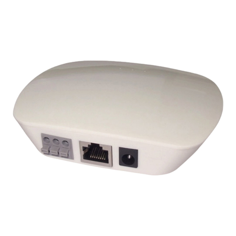
This Wireless Remote Control and Wireless Receiver (AL-60-03-0004
– sold separately) work together to provide mode, color, brightness,
and zone control for both Radialux®RGB and RGB-W tape lights.
The controller can operate up to four independent zones, so you can
have different color-changing effects in different rooms or parts of a
space. The remote can save up to three custom colors or modes. A
touch wheel allows for direct visual selection of colors.
Keypad Layout
Brightness Wheel
Choose a Zone number(s), for example 1 and 3, then touch the Brightness wheel to choose the desired brightness.
Brightness Up & Down Button
Short or long press the Brightness buttons to increase or decrease the brightness. The dimming direction will change each time the switch
is pressed. For example, the first long press increases the brightness, and the next long press dims down.
Brightness Button
Select a Zone (1, 2, 3, or 4). Press the 25%, 50%, 75% or 100% Brightness button for the corresponding brightness amount.
Save/Recall Button
1. Save brightness level: select a Zone (1, 2, 3, or 4), then adjust the brightness. Long press a Save button (1, 2, 3, or 4) for 2-3 seconds.
The LED lights will flash to indicate the level has been successfully saved.
2. To recall: select the zone to recall by pressing a Zone button (1, 2, 3, or 4), then short press one of the Save buttons (S1, S2, S3).
Operation
RF wireless LED remote controller
Four zones/areas
Press-button RGB+W controller
Model:SR-2819S with SR-1009Fxx
Parameter
Wiring diagram
Product Size
Brief introduction of buttons
Product introduction
SR-2819S RGBW remote controller has 4 different zones. It can get Red/ Green/ Blue/ White color directly. The
remote controller can save up to 3 colors or 3 modes into corresponding buttons (S1,S2,S3) for each zone.
You can choose any color through color wheel. you can set the system as RGB 3-channeloutput, or RGBW 4-
channel output.
Receivers work with WIFI-RF converter to be controlled by smart phone
Part No. Iuput Voltage Remarks
Current
SR-1009FA 12-36VDC Constant voltage
4x(60-180)W
4x5A
Output
SR-1009EA 12-36VDC Constant voltage
4x(96-288)W4x8A
Remote
Part No. Operation Voltage DIMENSIONS
ø/h (mm)
Operation
Frequency
SR-2819S 4.5VDC 48x140x16
434MHz/868MHz
Receiver
SR-1009FA3 12-36VDC Constant current
4x(4.2-12.6)W
4x350mA
SR-1009FA7 12-36VDC Constant current
4x(8.4-25.2)W4x700mA
Remarks
load 3pcs 7 AAA (1.5V)
batteries
Note:
One receiver can work with 1-8pcs SR-2819S
One SR-2819S control multiple receivers
The power supply chosen must be 20% higher than the actual load
Indicator: indicate the state of
remote control
White channel: the 4th channel
ON/OFF of all zones
4 zones: each zone can save
3 color or modes
Brightness: dim up
Brightness: dim down
S1
S2
S3
W
W+
Running button/Speed button ww nw and cw mixed by RGB
Save button
1)Receiver Connection Diagram for Single Unit
2) Connection Diagram for Multiple UnitsReceiver
Power Supply
12-36VDC
LN
110V-230VAC
whi te
SR-1009FA
LED CONTROLLER
1234
Lea rni ng Key
white
SR-1009FA
LED CONTROLLER
1234
Lea rni ng Key
white
SR-1009FA
LED CONTROLLER
1234
Lea rni ng Key
Power Supply
12-36VDC
LN
110V-230VAC
white
SR-1009FA
LED CONTROLLER
1234
Learning Key
Color wheel
55.0
17.
120.0
ISO 90 01:20 08
5
4.72 in.
0.67 in.
2.17 in.
Dimensions
v2.2

page 2 of 2
www.AlloyLED.com / support@AlloyLED.com / 800.910.LEDS (5337)
Specifications subject to change without notice.
Setup
How to Pair the Wireless Receiver (AL-60-03-0004) and Remote Control
1. Connect the components according to the diagram on the other side of this sheet.
2. Wake up the remote control by touching the ON/OFF button. The red power indicator will light up.
3. Short press the "Learning Key" button on the receiver.
4. Touch any of the 4 zone buttons on the remote control. If only setting up one zone, simply press the "1" button.
5. Then touch the color wheel.
6. The connected LED lights will blink to confirm the zone designation.
How to Unpair the Wireless Receiver and Remote Control
1. Hold down the "Learning Key" button on the receiver for about 5 seconds. When the LED lights flash, the remote has been unpaired.
Multiple Zones and Multiple Remote Controls
Note: Only one master controller can be assigned to each zone. After a period of time, the master will do a synchronization operation to keep the
same color or mode of all receivers in one zone.
1. To Set Up Multiple Zones: Each remote controller can control up to 4 zones via the Wireless Receivers, and multiple Wireless Receivers
can be set to a single zone. To set up multiple zones, repeat the steps above in "How to Pair", assigning each zone its own number from
1-4.
2. To Set Up Multiple Remotes to Control the Same Wireless Receiver: Each Wireless Receiver can be controlled by a maximum of 8
different remote controllers. To set up, repeat the steps above in "How to Pair" for each remote.
Wiring Diagram
Other ALLOYLED Switch manuals
Popular Switch manuals by other brands
Secureye
Secureye S-16GE-2UG-LD-AI-VLAN user manual

Provib Tech
Provib Tech VS102 user manual
H3C
H3C S9500 Series Operation manual
Omnitron Systems Technology
Omnitron Systems Technology iConverter GX/X user manual

Ocean Matrix
Ocean Matrix OMX-9003 instruction manual

schmersal
schmersal TQ200 operating instructions
Ovislink
Ovislink 16-Port Fast Ethernet 10/100Mbps N-Way... user guide
Intellisystem
Intellisystem IT-ES7110-IM-2GS Series user manual
Intermatic
Intermatic ET1100 Series Installation and user instructions
Bühler technologies
Bühler technologies Nivotemp NT MD Brief instructions

DirekTronik
DirekTronik 25-0577 Operation manual
H3C
H3C Aolynk ET204 quick start
