AllSolus LiveBase User manual

AllSolus LiveBase™ Quick Installation Guide
SAFETY WARNING: AllSolus products should be installed by a qualified electrician.
AllSolus LiveBase is a data-logging, monitoring and net-
working device for energy management applications.
Check you have each AllSolus LiveBase component prior
to installation:
♦ 1 x LiveBase unit plus whip antenna
♦ 1 x 12v Power Supply (AC power point required)
♦ 1 x Ethernet Cable for LAN or wireless modem connection
♦ 1 x USB Cable for PC Configuration
♦ 1 x SD card for long-term data storage
♦ 8 x 2 pin connectors for pulse and analog signal inputs
♦ 2 x 4 pin connectors for RS485 data inputs
♦ 1 x CD ROM with user manuals, USB drivers and configura-
tion software
Use the marking template at the bottom of this
page to mark drill holes for mounting the Live-
Base unit using the keyholes on the underside of
the device.
AllSolus recommends using pan-head screws
with a thread no wider than 4mm (0.157”) and a
head no wider than 3mm (0.118”).
IMPORTANT: Always mount LiveBase at least 1
metre (3.3 feet) from an Inverter to avoid electri-
cal interference.
Carefully screw the whip antenna onto the
unit. Ensure the antenna is positioned verti-
cally to maximize RF reception.
IMPORTANT: If the LiveBase unit is sur-
rounded by metal obstacles like metal cubi-
cles, an external antenna will be required to
replace the whip antenna.
Connect devices to the LiveBase inputs using the connectors supplied. Connect an Ethernet cable to LiveBase
from either a LAN or Sierra Wireless Airlink Raven XE modem. Check LiveBase LEDs to confirm Ethernet and
input connections. Note: Contact your electricity provider to obtain a power meter pulse signal output.
LiveBaseSMAAuroraCarlo
Gavazzi
Signal+B2+T/R15
Signal‐ A7 ‐T/R14
GroundO5RTN13
LiveBase Drill Template
Drill Here
Drill Here
Insert the SD card into the SD Card slot and en-
sure it clicks into place. Next, attach the 12v power
supply to the unit using the input labeled
When power is first attached the Power LED flash-
es and the other LEDs illuminate solid green while
the device initializes and performs a self test. After
approximately 30 seconds only the Power LED
flashes until other inputs are detected.
Successful operation can be confirmed using the Config Software Utility (see over),
or check the green LED status indicators on the unit.
Note: Connect one input
only, then replace with
each single input in turn to
detect a data problem for
LEDs using multiple inputs
LiveBase Status Indications

Quick Install Part 2: AllSolus Device Configuration
After installing your device, check and program input configuration using AllSolus Energy Management software supplied
on CD ROM with LiveBase. Important: Reboot your AllSolus device after changing Communication and Ethernet Settings.
Insert the AllSolus CD
ROM in your PC and copy
the USB device drivers and
AllSolus “Configuration
Utility” folder onto your PC.
Open the “Configuration
Utility” folder and double-
click the “setup.msi” file
to launch the AllSolus
Config Utility Setup
Wizard, then click Next
to proceed.
Select “I Agree” in the li-
cense agreement dialog
and click Next. Then select
an installation folder on
your PC and click Next.
Finally, click Next again to
confirm installation.
Attach a USB cable between
your PC and the AllSolus de-
vice you are configuring.
When configuring AllSolus
MeterLink™ units loosen the
4 screws on the MeterLink
cover to access the mini-USB
connector within the unit. MeterLink USB Connection
From the Start menu
on your PC select All
Programs > AllSolus
> AllSolus Configu-
ration Utility to
launch the Configura-
tion program.
Click Connect
to open the
Connection
Dialog.
Click the USB button, then click the drop-down
arrow below to select the COM port being used
by the PC for USB configuration. Then click Ok
to proceed. Note: if several COM ports are
listed, remove the USB cable, check the ports
in the drop-down list, then plug the device USB
cable into the PC. Check the list again and se-
lect the new port populated in the list.
After connecting
successfully
click to select
the Calculation Map tab. This
tab is used to map AllSolus
calculation engines to various
analog and digital inputs at-
tached to a connected AllSolus
device. Devices can then be
monitored using the AllSolus
Public online web display or
Local Network Portal.
Start at Calculation Engine
1 and click the drop-down
arrow for Calculate from
Input,then select an input
source, in this example
RS485—SMA Inverter.
Then select how this will be
represented in AllSolus
management software.
If pulse inputs are connected (e.g. SO1,
SO2, SO3), pulse periods and values
must be configured within the AllSolus
Calculation Map tab to match each
specific device’s pulse output. Check
with the manufacturer of each input de-
vice for more information.
Additional AllSolus Support: For additional configuration information view
AllSolus user manuals online at www.allsolus.com.au.
For product support contact your nearest AllSolus distributor.
For Technical Support email support@allsolus.com.au
The Channel and Encryption Passkey is
preset by default. All devices on the same
network must have the same setting for
both. This only needs to be changed if multi-
ple systems are operating within a close
range. To adjust this setting click the Gen-
eral Device Setting tab and enter a differ-
ent Channel and Encryption Passkey.
AllSolus recommends using the site name
when programming multiple passkeys.
In this example, Green Power. Program a Calculation Engine for
each input. Important: Click Write after completing any changes
and click Read to confirm settings have been programmed.
Table of contents
Popular Data Logger manuals by other brands

Co2meter
Co2meter CM-0001 user manual

Intempco
Intempco CX402-VFC205 manual

Delta
Delta PPM DC1 100 Series Operation and installation manual
FRONIUS
FRONIUS Datalogger Web operating instructions
CanadianSolar
CanadianSolar CSI-GL-WIFI-STICK Installation & commissioning manual
Co2meter
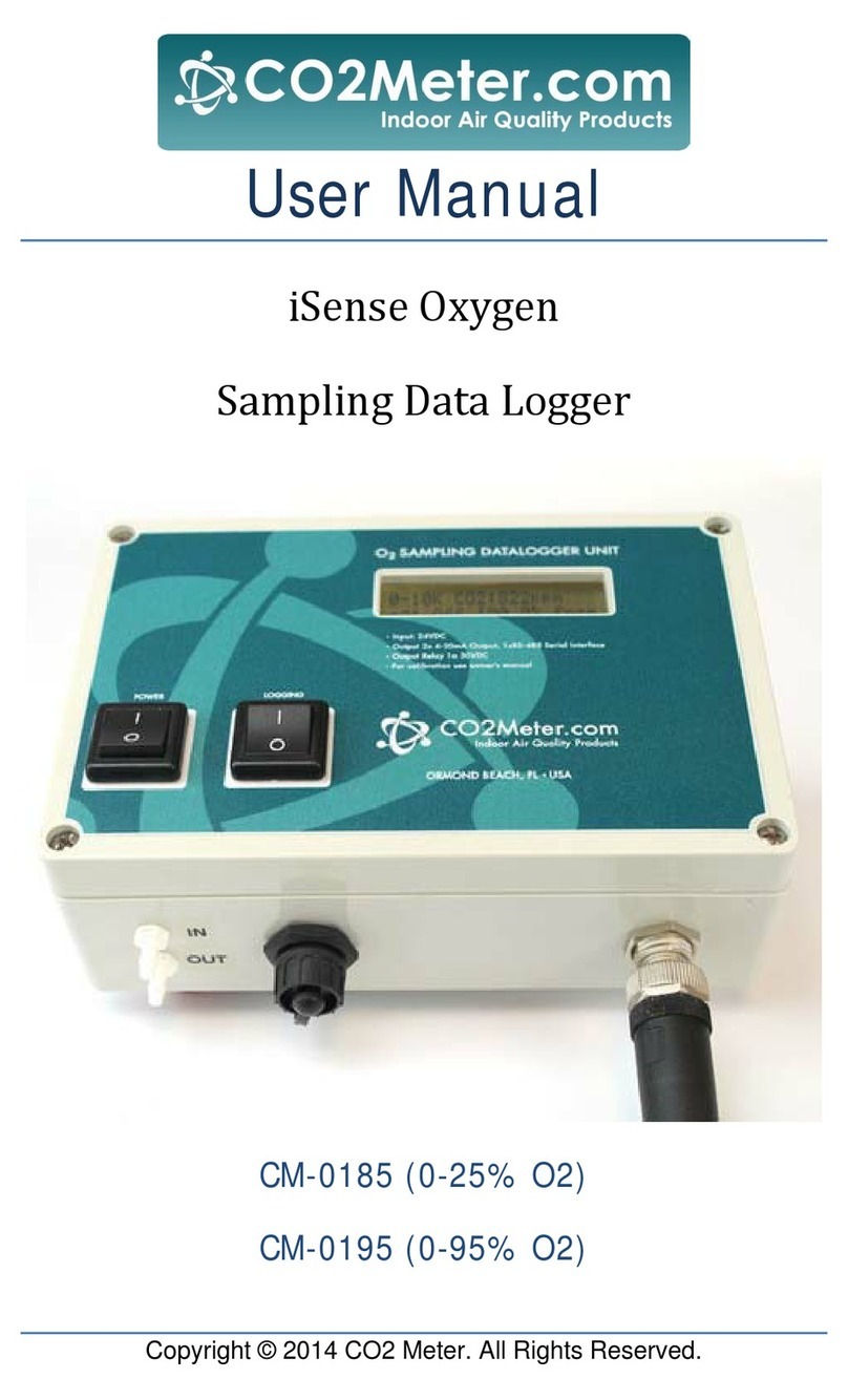
Co2meter iSense Oxygen user manual
