6 7
Safety
Safety edge
The Safety Edge is tted to the bottom of the
door and is activated when the door starts to
close. If it comes into contact with an object while
the door is closing, it transmits a signal to the wall
mounted control unit, the door will then stop and
reopen a short distance.
The safety edge also works as a weather seal,
designed to be pressed against the ground. The
bottom slat transmitter\cable has an IP rating
of IP54 and is protected against dust and water
splashing.
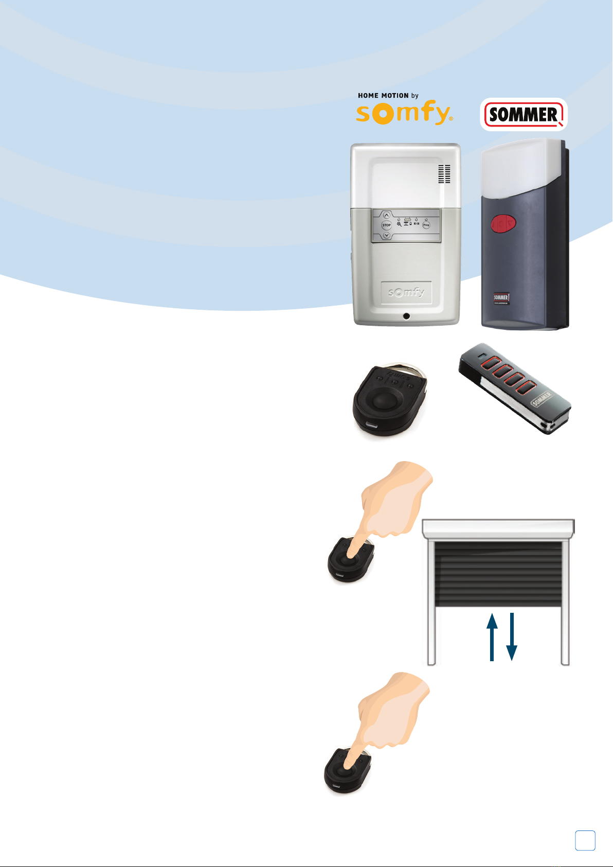
Safety Devices
The standard remote control receiver unit is
supplied with either an electrical wireless safety
edge or optical wired safety edge.
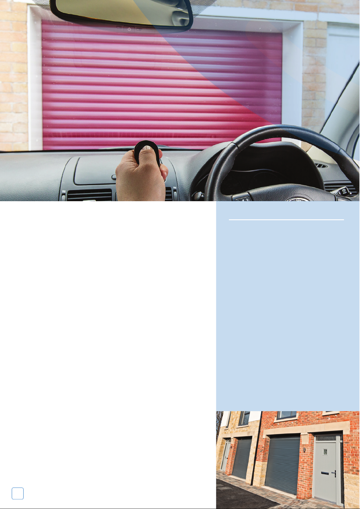
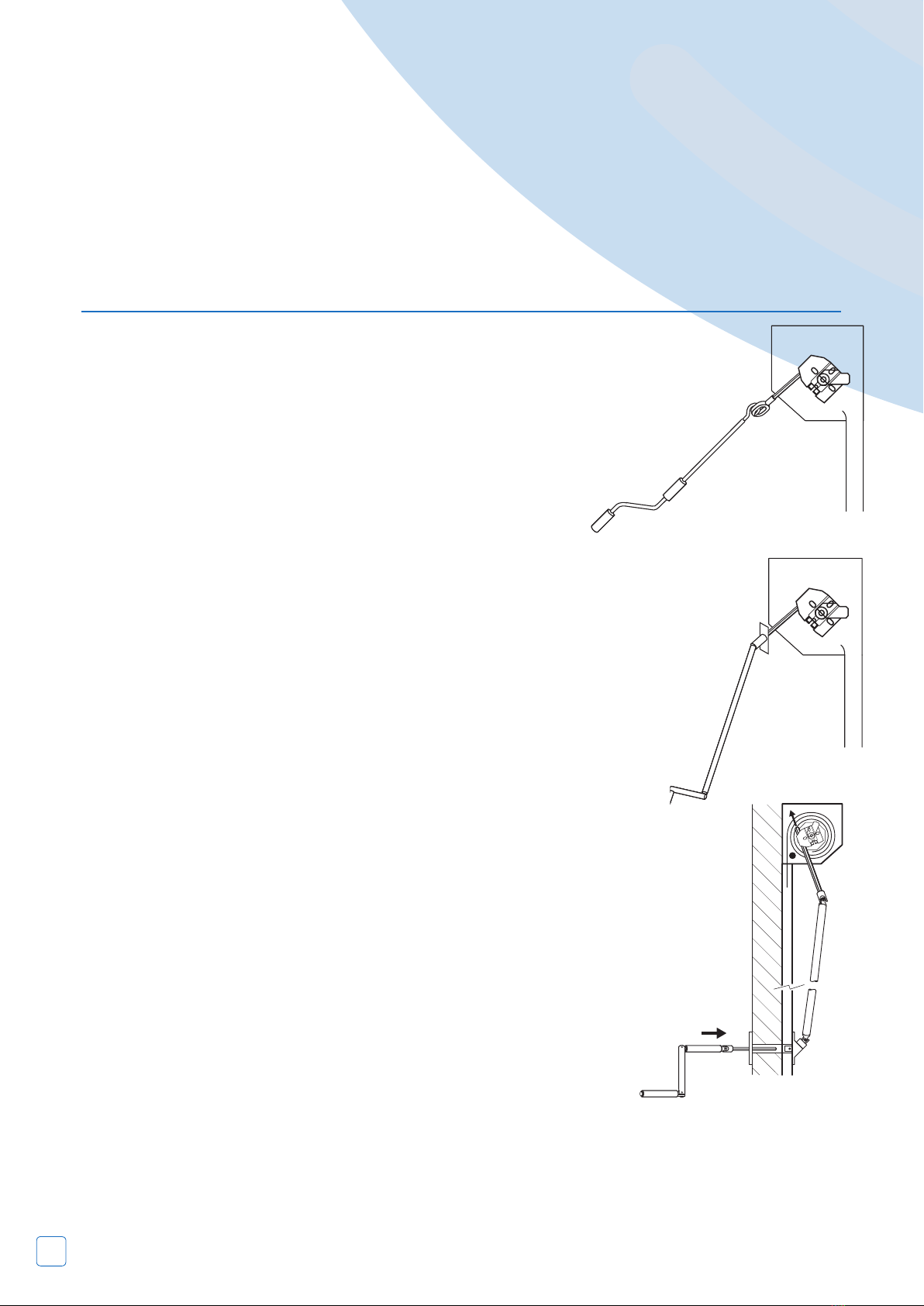
To operate:
Hold crank handle in
line with eye and rotate
handle until the door
reaches the
open/closed
position.
To operate:
Externally tted doors will need
the cover cap or
override lock removing
and the crank handle inserting.
Rotate
handle until the
door reaches
the open/closed
position.
To operate:
Remove lock and insert crank
handle and rotate until door
reaches the open/close position.
DO NOT OVERWIND
When the main power is reinstalled, ensure
that the power isolator is switched back on.
If applicable secure the handle back onto the
wall. Remember to keep the crank handle in a
convenient place.
Power Failure
Electrically Operated Products
If your roller garage door is not working
correctly please contact your installer for
assistance. N.B: Always isolate the power before
attempting to make an adjustment or repair.
Untrained operators are advised to contact an
approved installer.
Power failure
In the event of disruption to the power supply,
or the motor temporarily over heating (the
motor is protected by a thermal cut out), the
door can be operated manually. Isolate power
supply before using the manual override.
To operate: Hold crank handle in line with eye
and rotate handle until the door reaches the
open/closed position.
If the door is not used during the power
failure then no action has to be taken as
the unit will reset itself when the power is
restored.
Important
If the garage has no service door then an
exterior release kit should have been tted
to allow emergency opening from outside.
Follow instructions supplied with that kit.
Note
When closing the door manually ensure that the
locking joints are set in the fully closed position to
ensure security.
Insert the hooked end of the winding handle into
the override eye; this is projecting downwards from
the drive motor at one end of the curtain roll, rotate
the handle to operate the door to open or close.