manuals.online logo
Brands
  1. Home
  2. •
  3. Brands
  4. •
  5. Allweiler
  6. •
  7. Water Pump
  8. •
  9. Allweiler AE1L Series Manual

Allweiler AE1L Series Manual

1
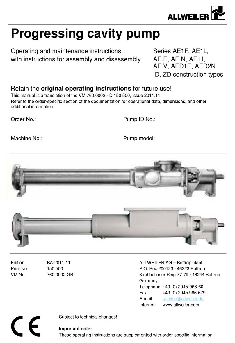
Operating and Maintenance Instructions VM No.: 760.0002 GB
with Dismounting and Edition: 02.04
Mounting Instructions Ident No.: 150 500
Eccentric Screw Pumps
Series AE1L, AE.E, AE.N, AE.H, AE.V,
AED1E, AED2N
Design ID, ZD
Order No.: Ident No. of Pump:
Machine No.: Pump Type:
Operating data, dimensions and other additional information can be found in the order-specific part of the documentation.
Contents
1. General
2. Safety
3. Transport and Intermediate
Storage
4. Description
5. Installation/Mounting
6. Start-up/Shutdown
7. Maintenance/Repair
8. Operating Faults, Causes
and Remedial Action
Important note:
This operating manual is to be supplemented
by the order-related information.
Retain
for future
use!
These Operating and Maintenance In-
structions contain information from the
pump manufacturer. They may need to
be supplemented by instructions of the
operator company for its personnel.
These instructions do not take account
of specific information relating to opera-
tion and maintenance of the process
plant into which the pump is integrated.
Such information can only be given by
the persons responsible for construction
and planning of the plant (plant manu-
facturer).
Such specific instructions relating to
operation and maintenance of the
process plant into which the pump is
integrated have priority over the in-
structions of the pump manufacturer.
The plant manufacturer must on princi
-
ple observe the limits of use!
Refer to the operating instructions of th
e
plant manufacturer!
2
Baureihen AE1L, AE.E, AE.N, AE.H, AE.V, AED1E, AED2N
Bauform ID, ZD
Table of Contents
1. General
1.1 Application and range of utilization
1.2 Performance data
1.3 Abbreviation
1.4 Warranty
1.5 Testing
2 . Safety
2.1 Marking of hints in the operating instructions
2.2 Personnel qualification and personnel training
2.3 Dangers in case of non-compliance with the safety hints
2.4 Responsible working
2.5 Safety hints for the user/operator
2.6 Safety hints for maintenance, inspection and mounting
operations
2.7 Independent reconstruction and spare parts production
2.8 Inadmissible modes of operation
2.9 Operation in potentially explosive environments
3. Transportation and intermediate storage
3.1 Packing
3.2 Transportation
3.3 Preservation and storage of eccentric screw pumps
4. Description
4.1 Structural design
4.1.1 Bearing ans lubrication
4.1.2 Shaft seal
4.1.3 Dimensions/branch position/flanges
4.2 Sound pressure level
4.3 Mode of operation
4.4 Aggregate construction
4.4.1 Drive
4.4.2
Shaft coupling and protection against accidental
contact
4.4.3 Base plate
5. Installation/Mounting
5.1 Installation
5.2 Foundation
5.2.1 Arrangement of a steel foundation plate
5.2.2 Arrangement of concrete foundations
5.2.3
Fastening of the pump aggregate on the concrete
foundations
5.2.4
Arrangement of concrete foundations for poured
base plates
5.2.5 Pouring of base plate
5.3 Base plate
5.4 Coupling
5.5 Assembling of pump and drive
5.6 Drive by V-belt drive
5.7 Space required for maintenance and servicing
5.8 Installing of pipelines
5.8.1 Nominal widths
5.8.2 Supports and flange connections
5.8.3 Cleaning of pipelines prior to attachment
5.9 Installing of auxiliary pipelines for additional facilities
5.10 Safety and control facilities
5.10.1 Manometer and vacuumeter
5.10.2 Safety installation in the pressure pipeline
5.11 Electrical connections
6. Start-up/Shutdown
6.1 Preparations for start-up
6.1.1 Filling the pump with liquid
6.1.2
Turning on the additional facilities for shaft seals (if
provided)
6.1.3
Quality and properties of the flushing/sealing and
quenching liquid
6.1.4
Turning on the additional facilities for heating or
cooling the stuffing box casing and/or the suction
casing (double-jacket casing)
6.1.5 Breaking away of the pump
6.1.6 Control of the sence of rotation
6.2 Start-up
6.2.1 Start-up
6.2.2 Drive
6.2.3 Checking the delivery values
6.2.4 Protection against running dry
6.3 Shutdown
6.3.1 Shutoff
6.3.2 Measures in case of longer periods of standstill
7. Maintenance/Repair
7.1 Maintenance
7.1.1 General monitoring
7.1.2 Maintenance of components
7.1.2.1 Joints of the joint shaft
7.1.2.2
Bearing of the drive shaft and lubrication of the bear-
ings
7.1.2.3 Shaft sealing
7.1.2.4 V-belt drive
7.1.2.5 Drive engines and (variable speed gear) drive
7.1.2.6
Packing ring dimensions (for Chapter 7.1.2.3), lubri-
cant quantities for joints (for Chapter 7.1.2.1), bear-
ings (for Chapter 7.1.2.2) and flushing liquid flows
(for Chapter 6.1.2)
7.2 Repair (dismounting and mounting instructions)
7.2.1 Dismounting of the eccentric screw pump
7.2.1.1 Dismounting the stator
7.2.1.2 Dismounting the rotor and the rotor-side joint
7.2.1.3 Dismounting the joint shaft and the drive-side joint
7.2.1.4 Dismounting the shaft seal and the drive shaft
7.2.1.5
Dismounting the angular contact and groove ball
bearings
7.2.2 Mounting of the eccentric screw pump
7.2.2.1
Installing the angular contact and groove ball bear-
ings
7.2.2.2 Installing the shaft seal with dismounted drive shaft
7.2.2.3 Installing the drive shaft with shaft seal
7.2.2.4 Installing the rotor and rotor-side joint
7.2.2.5 Installing the joint shaft and the drive-side joint
7.2.2.6 Installing the stator
7.3 Replacement parts/spare parts
7.4
List of individual parts and recommended replacement
parts/spare parts
7.5
Sectional drawing for series AE1L, AE1E, AE2E, AE1N, AE2N,
AE4N, AED1E, AED2N; Design ID
7.6
Sectional drawing for series AE1+1H, AE2+2H, AE2+2V,
AE4+4V; Design ID
7.7 Sectional drawing for series AE2H, AE4H; Design ID
7.8 Sectional drawing for series AE1N, AE2N; Design ZD
7.9 Sectional drawing for series AE1+1H, AE2+2H; Design ZD
7.10 Sectional drawing for series AE2H, AE4H; Design ZD
8. Operating faults, causes and remedial action
3
Series AE1L, AE.E, AE.N, AE.H, AE.V, AED1E, AED2N
Design ID, ZD
1. General
1.1 Application and range of utilization
The eccentric screw pumps are self-priming, rotary
positive-displacement pumps for handling and dosing
low to high-viscosity, neutral or aggressive, pure or
abrasive, gaseous liquids or liquids which tend to
froth, even with fibre and solids contents.
The range of utilization is to be
taken from the order data sheet.
1.2 Performance data
The exact performance data applying to the pump
are to be taken from the order data sheet and are
engraved on the name plate.
1.3 Abbreviation
The abbreviation of the eccentric screw pumps is set
up according to the following scheme:
Example:
This abbreviation is embossed on the type plate.
1.4 Warranty
Our liability for shortcomings in the supply is laid down
in our delivery conditions. No liability will be under-
taken for any damages caused by non-compliance
with the operating instructions and service conditions.
If at any later date the operating conditions happen to
change (e.g. different liquid pumped, speed, viscosity,
temperature or pressure conditions), it must be
checked by us from case to case and confirmed, if
necessary, whether the pump is suited for these pur-
poses. In case no special agreements were made,
pumps supplied by us may, during the warranty pe-
riod, be opened or varied only by us or our authorized
contractual service stations; otherwise, our liability for
any defects will cease.
1.5 Testing
Prior to leaving our factory, all pumps are subjected to
a leakage and performance test. Only properly oper-
ating pumps leave the factory achieving the perform-
ances assured by us. Thus, compliance with the fol-
lowing operating instructions ensures proper opera-
tion.
2. Safety
These operating instructions contain basic hints to be
observed in case of installation, operation and main-
tenance. Therefore, prior to mounting and commis-
sioning, these operating instructions must by all
means be read by the fitter as well as the pertinent
expert personnel/customer and must always be avail-
able at the place of installation of the machine/ plant.
Not only are the general safety hints listed under this
main item „Safety“ to be observed, but also the spe-
cial safety hints such as for private use added to the
other main items.
2.1 Marking of hints in the operating instructions
The safety hints contained in these operating instruc-
tions which, in case of non-compliance, may cause
danger to personnel, are particularly marked with the
general danger symbol
in case of warning against electric voltage with
For safety hints, non-compliance with which may
cause dangers to the machine and its functions, the
word
is inserted.
Hints directly attached to the machine such as
! directional marker
! signs for fluid connections
must by all means be observed and maintained in
completely legible condition.
2.2 Personnel qualification and personnel training
The personnel for operation, maintenance, inspection
and mounting must have the corresponding qualifica-
tion for these operations. Range of liability, compe-
tence and the supervision of the personnel must be
exactly controlled by the customer. If the personnel do
not have the required knowledge, same must be
trained and instructed. If required, this may be ef-
fected by the manufacturer/ supplier on behalf of the
machine customer. In addition, it must be ensured by
the customer that the contents of the operating in-
structions are fully understood by the personnel.
2.3 Dangers in case of non-compliance with the safe-
ty hints
Non-compliance with the safety hints may result in
danger not only to persons, but also to environment
and machine. Non-compliance with the safety hints
may lead to the loss of any claims for damages. In
detail, non-compliance may, for example, entail the
following dangers:
4
Series AE1L, AE.E, AE.N, AE.H, AE.V, AED1E, AED2N
Design ID, ZD
! failure of important functions of the machine/plant
! failure of specified methods for maintenance and
servicing
! danger to persons by electrical, mechanical and
chemical influences
! danger to the environment by leakage of danger-
ous substances
2.4 Responsible working
The safety hints mentioned in these operating instruc-
tions, the current national rules for the prevention of
accidents as well as any internal working, operating
and safety regulations of the owner must be ob-
served.
2.5 Safety hints for the user/operator
! If hot or cold machine parts lead to dangers, these
parts must be protected against accidental contact
at the site.
! Protection against accidental contact for moving
parts must not be removed when the machine is
in operation.
! When operating pump aggregates in a dust-laden
environment (e.g. milling, chipboard manufacture,
bakeries), the surface of the pumps and motors
must be cleaned at regular intervals, depending
on local conditions, in order to maintain the cool-
ing effect and eliminate the possibility of sponta-
neous combustion. Please also see explosion pro-
tection regulations (BGR 104).
! Leakages (e.g. of the shaft seal) of dangerous
materials to be handled (e.g. explosive, toxic, hot)
must be discharged so as not to result in danger
to persons and the environment. Legal stipula-
tions are to be observed.
! Dangers by electrical energy are to be excluded
(for details with regard hereto, please refer e.g. to
the regulations of the VDE and the local energy
supply associations).
2.6 Safety hints for maintenance, inspection and mo-
unting operations
The customer shall see to it that all maintenance, in-
spection and mounting operations are performed by
authorized and qualified expert personnel who have
sufficiently informed themselves by thoroughly study-
ing the operating instructions.
Basically, operations at the machine must be per-
formed during standstill only. The mode of operation
for stopping the machine described in the operating
instructions must by all means be observed.
Pumps or aggregates handling noxious liquids must
be decontaminated.
Immediately upon completion of the operations, all
safety and protective devices must be mounted and
made operational again.
Prior to restarting, the items listed in Chapter “Prepa-
ration for start-up” are to be observed.
2.7 Independent reconstruction and spare parts pro-
duction
Reconstruction of or changes to the machine are only
admissible after consultation with the manufacturer.
Original spare parts and accessories authorized by
the manufacturer serve safety purposes. The use of
other parts may cancel the liability for the conse-
quences resulting therefrom.
2.8 Inadmissible modes of operation
The operating safety of the machine supplied is only
ensured with due application according to Chapter 1
“General” of the operating instructions. The limit val-
ues given in the data sheet must by no means be ex-
ceeded.
2.9 Operation in potentially explosive environments
Observe the instructions of the ATEX additional oper-
ating manual when operating the pump respectively
aggregate in potentially explosive environments.
3. Transport and intermediate storage
3.1 Packing
The symbols applied to the packing must be ob-
served.
During transportation and storage, suction and outlet
side and auxiliary connections of the pump must be
closed with plugs. During installation of the pump ag-
gregate, the plugs must be removed.
3.2 Transportation
The pump or pump aggregate is to be safely trans-
ported to the place of installation, if required by
means of lifting gear.
The regulation for lifting loads in accordance with
VBG 9a must be observed. Crane and sling
equipment must be adequately dimensioned.
Sling equipment must not be secured to the lifting
eyes of the motor, except as additional protection
against overturning in the event of nose-
heaviness.
When transporting the pump by crane, place the
stopper ropes safely around the suction casing. With
complete pump aggregates, an additional rope must
be slung around the drive engine.
The stopper ropes have to be slung around the pump
respectively pump aggregate so that these are ex-
actly balanced when lifted.
Transportation to and at the installation site
Make sure, that the unit is transported safely and in a
stable position. Overturning due to nose-heaviness
must be prevented.
Transport damages
Check the pump for damage on
receipt. Any damage detected must
be notified immediately.
3.3 Preservation and storage of eccentric screw
pumps
Please refer to our document VM 2102/ …
5
Series AE1L, AE.E, AE.N, AE.H, AE.V, AED1E, AED2N
Design ID, ZD
4. Description
4.1 Structural design
Self-priming, one or two-stage eccentric screw pump.
The conveyor elements are rotor and stator. The input
torque is transmitted via the drive shaft and the joint
shaft to the rotor.
Pressure casing, stator and suction casing are held
together by external casing connection screws (clamp
bolts).
The stuffing box or mechanical seal housing is lo-
cated between the suction casing and the bearing
bracket.
4.1.1 Bearing and lubrication
Joint shaft with liquid-proof clad bolt joints. Greasing
with joint oil.
Bearing of the drive shaft in the bearing bracket
through greased angular contact and groove ball
bearings. Bearings protected against water jets.
4.1.2 Shaft seal
Through uncooled or cooled stuffing box or cooled or
uncooled, maintenance-free, non-released, singular
or double-acting mechanical seal.
4.1.3 Dimensions/branch position/flanges
The dimensions of the pump respectively the pump
aggregate, the branch position and flange dimensions
are to be taken from the tables of dimensions.
4.2 Sound pressure level
The sound pressure level of the pump is below 70 dB
(A).
4.3 Mode of operation
Self-priming, rotating positive-displacement pump.
Conveyor elements are the rotating helical rotor and
the static stator. Both touch in transection with series
AE.E, AE.N, AE.H, AE.V in two points each and with
series AE1L, AED1E, AED2N in three points each,
which form two sealing lines seen across the length of
the conveyor elements with series AE.E, AE.N, AE.H,
AE.V and three sealing lines with series AE1L,
AED1E, AED2N. The content of the sealed chambers
that form with the rotation of the rotor is shifted axially
and totally continuously from the suction to the outlet
side of the pump. No turbulence occurs despite the
rotation of the rotor. The unvarying chamber volume
rules out crushing forces and thus guarantees very
gentle, low-pulsation conveyance.
4.4 Aggregate construction
4.4.1 Drive
By means of non-explosion-protected or explosion-
protected electric motors, geared motors or variable
speed gear motors. Other drive variants (e.g. via V-
belts) are possible.
4.4.2 Shaft coupling and protection against accidental
contact
Shaft coupling according to DIN 740.
A protection against accidental contact according to
DIN EN 809 is attached as soon as the scope of sup-
ply comprises pump, base plate, shaft coupling and
drive.
According to the rules for the prevention of acci-
dents, the pump must be started only with a pro-
tection against accidental contact according to
DIN EN 809.
If a protection against accidental contact is not sup-
plied, same is to be installed by the operator.
4.4.3 Base plate
The pumps of horizontal installation are, as a rule,
mounted with the drive on a common base plate.
Base plates are provided of the steel type of construc-
tion.
5. Installation/Mounting
5.1 Installation
The pumps can be installed horizontally or vertically
with bearing upwards.
5.2 Foundation
The foundation design depends on the size of the
pump and/or the pump aggregate and the local instal-
lation conditions.
For exact data on the pump and aggregate dimen-
sions, please refer to our tables of dimensions.
The foundation may be designed as concrete founda-
tion or load-carrying foundation frame, for example of
the steel type.
All foundation designs are subject to the following:
The foundation must be designed so that it can take
the weight of the pump aggregate on the entire sur-
face.
5.2.1 Arrangement of a steel foundation plate
A steel foundation plate must be designed in such a
way that the base plate makes full contact and can be
secured with bolts or by welding.
If only some of the areas of the
base plate are supported, the plate
sags in the center or the pump aggregate can be
twisted. This influences the alignment of the pump
aggregate can cause high noise emission and dam-
age.
5.2.2 Arrangement of concrete foundations
Concrete foundations must be horizontal, straight and
clean and must fully absorb the load exerted on the
foundations. Concrete foundations must be designed
in such a way that the base plate makes full contact
and can be secured with suitable bolts (see our ag-
gregate drawing).
If only some of the areas of the
base plate are supported, the plate
sags in the center or the pump aggregate can be
twisted. This influences the alignment of the pump
aggregate and can cause high noise emission and
damage.
5.2.3 Fastening of the pump aggregate on the concrete
foundations
After aligning the pump aggregate on the concrete
foundations the securing bolts are diagonally and
evenly tightened.
5.2.4 Arrangement of concrete foundations for poured
base plates
When shuttering the concrete foundations it must be
observed that a gap for aligning the pump aggregate
and applying the mortar compound remains between
the top of the finished foundation block and the bot-
tom of the base plate.
6
Series AE1L, AE.E, AE.N, AE.H, AE.V, AED1E, AED2N
Design ID, ZD
The set concrete foundations must be straight, even
and clean. Any traces of oil must be removed from
the foundations. The recessed anchor holes for the
foundation bolts must be cleaned and removed and
cleaned out with air. Prior to the installation of the
pump aggregate the surface of the concrete founda-
tions must be roughened and cleaned to ensure a
good bonding between the foundation block and the
mortar compound.
5.2.5 Pouring of base plate
After alignment on the concrete foundations , a low-
shrinkage mortar compound must be poured over the
entire length of the base plate, covering also the an-
chor holes with the connected foundation bolts.
Once the mortar compound has set on the base plate
and in the anchor holes, the foundation bolts must be
diagonally and evenly tightened.
Note: When pouring or adding the mortar compound
it must be observed that the base plate makes full
contact. Tap the plate to ensure that no cavities have
formed underneath.
5.3 Base plate
The base plate must be fixed on the foundation, ten-
sion-free.
5.4 Coupling
A pump aggregate supplied complete was carefully
mounted at the factory. As the pump and the drive are
fixed on the base plate, re-alignment of the coupling is
not required.
5.5 Assembling of pump and drive
If the aggregate is first completed on site, you need to
assemble the clutch as follows:
1. Thinly coat the pump and drive shafts with molyb-
denum sulfite (e.g. Molykote) and insert the
feather keys.
2. Wind up the pump and the motor-side clutch half
with the aid of a windup device so far until the
shaft end is aligned with the clutch hub. If no
windup device is available, heating the clutch
halves to approx. 100°C (without rubber buffers)
eases sliding on.
3. Fixate the clutch halves axially with a grub screw
(DIN 916).
4. When assembling the pump and the motor, the
drive motor respectively variable speed gear,
make sure that the clutch halves are exactly
aligned and that the distance between the cou-
pling halves is observed (see our aggregate draw-
ings and the details by the clutch manufacturers).
5. Install a contact protection in acc. with DIN EN
809.
5.6 Drive by V-belt drive
In case of a V-belt reduction from drive to pump,
make sure that two V-belt pulleys are aligned in paral-
lel.
The V-belt pulleys must be pushed onto the shaft
ends as far as possible. It must be possible to regu-
late the tension of the V-belts by means of a motor
rocker or by means of tensioning rails. They must be
slightly retightened after a short running-in period.
Excessive tensioning will destroy
the rolling bearings of the pump.
Our separate instructions “V-belt drive” (VM 706.0001
GB, Ident No. 133586) must be complied with.
5.7 Space required for maintenance and servicing
The pump must be accessible from
all sides in order to be able to per-
form the required sight inspections.
There must be enough room for maintenance and
service work, especially for the exchange of the con-
veyor elements. The stator and rotor dismounting di-
mensions are listed in the pump respectively pump
aggregate dimension sheet. Also make sure that all
pipelines can be attached/detached without obsta-
cles.
5.8 Installing of pipelines
5.8.1 Nominal widths
The nominal widths of the suction and pressure pipes
should be designed according to the nominal widths
of the pipe connections. Gross deviations, especially
on the suction side, require consultation with the fac-
tory.
5.8.2 Supports and flange connections
The pipelines must be connected tension-free to the
pump via the flange connectors. They have to be
supported near the pipe and should be easy to screw
on in order to avoid strains. After loosening the
screws, the flanges may neither be slanted nor
springy and also not rest on each other under pres-
sure. Possible thermal stress on the pipelines has to
be kept away from the pump by means of suitable
measures, e.g. the installation of compensators.
5.8.3 Cleaning of pipelines prior to attachment
The pipelines, sliders and valves on the suction side
must be rinsed respectively cleaned under all circum-
stances before installing the pump.
Leftover assembly parts like screws, nuts, welding
beads, pieces of steel, etc. destroy the inside parts of
the pump. Any warranty claim is void when damages
are caused by such leftover materials. Flange seals
may not protrude to the inside. Blind flanges, stoppers
protective foils and/or lacquers on flanges and sealing
strips have to be completely removed.
5.9 Installing of auxiliary pipelines for additional fa-
cilities
All auxiliary pipelines for supplying the shaft seal and
the possible double jacket casing for heating and
cooling the pump have to be connected tension-free
and sealing.
The pipes for the quenching liquid with single-acting
mechanical seals with quench (design: G0Q and
G1Q) and the sealing liquid with double-acting me-
chanical seal (design: G0D/G1D) should be installed
with a large flowtrough profile. The quenching respec-
tively sealing liquid discharge takes place at the high-
est connection of the mechanical seal housing.
The flow direction of the flushing, sealing and quench-
ing liquid is indicated with arrows in the section draw-
ings.
In order to ensure self-deairing, the pipes must be in-
stalled continuously rising, short and favorable for the
flow.
The formation of air pockets and gas bubbles has to
be prevented, install deairing connections if required.
The heating/cooling liquid discharge must be con-
nected to the highest connection of the possible dou-
ble-jacket casing.
7
Series AE1L, AE.E, AE.N, AE.H, AE.V, AED1E, AED2N
Design ID, ZD
5.10 Safety and control facilities
5.10.1 Manometer and vacuumeter
A manometer and vacuumeter have to be connected
to the pressure and suction pipe.
5.10.2 Safety installation in the pressure pipeline
As soon as a stop valve is arranged in the pressure
pipeline or if it is possible that the pressure pipeline
will be clogged, a safety element must be provided,
e.g.: by-pass line with installed excess pressure
valve, bursting diaphragm, protective motor switch
etc.
Eccentric screw pumps are positive-displace-
ment pumps and can theoretically generate an
infinitely high pressure.
In case of a closed pressure pipe, e.g. because of
clogging or accidental closing of the valve, the
pressure generated by the pump may reach a
multiple of the admissible plant pressure. This
may cause pipes to burst, which must be espe-
cially prevented when handling dangerous con-
veyor substances. Therefore, the corresponding
safety equipment (e.g. pressure switches) also
has be installed in the plant.
5.11 Electrical connections
Only an expert may attach the power cables of the
coupled drive engine in accordance with the circuit
diagram of the engine manufacturer. The valid guide-
lines of the Electrician's Association and the public
power companies have to be observed.
Danger by electrical energy must be excluded.
6. Start-up/Shutdown
6.1 Preparations for start-up
6.1.1 Filling the pump with liquid
The pump may not run dry! For
initial start-up and after longer peri-
ods of standstill, the pump must be filled with liquid.
Even a few rotations without liquid may damage the
stator. For that reason, the suction casing must be
filled with water or conveyor liquid prior to start-up for
lubricating the stator and rotor. After long periods of
standstill, meaning when it must be assumed that the
residual liquid in the pump has evaporated or after re-
pairs, you have to repeat the filling process.
After filling, the pump works in self-priming mode.
Deairing is not necessary, as the pump can convey a
liquid-gas mixture.
6.1.2 Turning on the additional facilities for shaft seals
(if provided)
If the pumps are charged with a flushing/sealing or
quenching liquid, the provided shut-off slides must be
opened before putting the pump into operation for the
first time and set to the following pressure values:
! Supply of the stuffing box with flushing or
sealing liquid (Design P02, P12, P03, P13, P04
and P14).
Note: Stuffing box with flushing or sealing cham-
ber ring require a flushing respectively sealing liq-
uid for maintaining the function.
The required flushing respectively sealing liquid
pressure for pumps with stuffing box is
P02/P12 = 0.1 to 0.5 bar
(above inner pressure of the suction casing)
P03/P13 = 0.5 bar
(above inner pressure of the suction casing)
P04/P14 = 0 to 0.5 bar
(Flushing and sealing liquid see Chapter 6.1.3.).
! Supply of single-acting, non-relieving me-
chanical seal with throttle ring (Design G0S/
G1S and G0T/G1T)
Note: These mechanical seals require a flushing
liquid in order to maintain their function, which car-
ries off the emerging friction heat and limits the
penetration of the conveyor liquid into the sealing
chamber.
The required flushing liquid pressure is 0.1 to 0.5
bar above the inner pressure of the suction cas-
ing. The required flushing liquid flow for carrying
off the dissipation of the mechanical seal is listed
in the table in Chapter 7.1.2.6 (flushing liquid see
Chapter 6.1.3).
! Supply of double-acting, non-relieving me-
chanical seal (Design G0D/G1D)
Note: These mechanical seals require a sealing
liquid in order to maintain their function, which car-
ries off the emerging friction heat and limits the
penetration of the conveyor liquid into the sealing
gap.
The circulation of the sealing
liquid must be secured prior to
each start-up.
The sealing liquid pressure must be approx. 1.5 to
2 bar above the pressure on the inside of the suc-
tion casing. The flowthrough quantity must be
regulated in such a way that the exit temperature
does not exceed approx. 60°C and is at least 30 K
below the boiling temperature at operating pres-
sure. The temperature difference between input
and output may amount to at most 15 K. (Sealing
liquid see Chapter 6.1.3).
! Supply of the single-acting mechanical seal
with quench (Design G0Q and G1Q)
The space between the mechanical seal counter-
ring and the shaft seal ring must be charged with
quenching liquid. The max. admissible pressure
difference between the quenching liquid pressure
and the pressure in the suction casing is p = 0,5
bar. The max. quenching liquid pressure is 3 bar.
(Quenching liquid see Chapter 6.1.3).
6.1.3 Quality and properties of flushing/sealing and
quenching liquid
Any liquid may be used as
sealing/flushing or quenching liquid
under consideration of the corrosion resistance of all
touching parts and the compatibility with the medium
to be sealed. The liquid must be free from solid sub-
stances, may not be prone to deposits, should have a
high boiling point as well as a good heat conductivity
and low viscosity. Clean and soft water fulfils these
requirements to a high degree.
8
Series AE1L, AE.E, AE.N, AE.H, AE.V, AED1E, AED2N
Design ID, ZD
6.1.4 Turning on the additional facility for heating or
cooling the stuffing box casing and/or the suction
casing (double-jacket casing)
If the pumps are equipped with these additional fea-
tures, all shut-off devices for heating or cooling sys-
tems must be opened. The following pressure and
temperature limits must be observed.
! Supply of the cooled or heated stuffing box
and/or suction casing (double-jacket casing)
with suitable liquid media
Only liquid media may be used as heating or
cooling liquid under consideration of the corrosion
resistance of all touching parts.
The maximum heating or cooling liquid pressure
is 6 bar. The maximum heating temperature may
not exceed 150°C and the cooling temperature
may not be below -40°C.
Note: The design temperature is listed in the or-
der data sheet.
6.1.5 Breaking away of the pump
When initially starting the pump or after longer periods
of standstill, you have to make sure that the drive en-
gine turns the pump effortlessly. Should this not be
easily possible due to the high adhesion between the
rotor and the stator in new state, use suitable tools on
the feather key section of the drive shaft to free the
pump.
The drive shaft may not be
damaged here!
6.1.6 Control of the sence of rotation
The normal rotation direction of the pump seen from
the drive against the drive shaft is to the left. Here the
suction connection is located on the side of the shaft
seal so that the shaft seal is relieved. In special
cases, e.g. when sucking from a vacuum or convey-
ing media that do not tolerate gas cavities, the pump
rotates to the right. This switches the suction and the
outlet side around.
The rotation direction of the pump
must correspond to the rotation
direction arrow "n" on the pump's type plate. A wrong
rotation direction may cause damages to the pump. In
order to control the rotation direction, briefly press the
on/off switch of the engine.
6.2 Start-up
6.2.1 Start-up
Prior to starting the pump, all shut-off devices on the
suction and outlet side have to be opened.
6.2.2 Drive
Turn the motor on.
Observe the product-specific peculi-
arities of the drive. See operating
instructions of the drive manufacturer.
6.2.3 Checking the delivery values
Once the drive has reached its operating speed,
check the intake pressure and the pump end pres-
sure via the vacuometer and the manometer.
The motor may not be overloaded. The power intake
can be monitored with an ammeter. Check the tem-
perature and the viscosity of the conveyor liquid in this
context. The resulting values must be compared with
the order data sheet respectively acceptance proto-
col.
6.2.4 Protection against running dry
When no more conveyor media is sucked in by the
pump, the thermal energy emerging in the conveyor
elements of the eccentric screw pump through dry
friction and milling work is no longer carried off in a
sufficient quantity, which thermally destroys the stator
elastomer after a short time already. There are differ-
ent protectors against running dry for protecting the
conveyor elements that are adapted to the respective
operating conditions (consultation with the factory).
6.3 Shutdown
6.3.1 Shutoff
Turn the motor off.
6.3.2 Measures in case of longer periods of standstill
If longer operational breaks are intended and if there
is danger of frost, the pump must be emptied. To do
so, unscrew the screw plug (502) from the suction
casing (505) and afterwards conserve the pump (see
Chapter 3.3).
7. Maintenance/Repair
7.1 Maintenance
! For service and maintenance work, observe the
details in Chapter 2 “Safety”.
! Regular monitoring and maintenance work on the
pump and the drive extends the service life.
7.1.1 General monitoring
1. The pump may not run dry.
2. The drive engine may not be overloaded.
3. Check the suction and pressure pipes for tight-
ness.
4. An installed stuffing boxmust drip slightly during
operation. An installed mechanical seal may not
have any strong leaks.
5. Monitor pressure and temperature monitoring de-
vices and compare them with the order data sheet
respectively acceptance protocol.
6. Additional installations like flushing, sealing and
quenching of the shaft seal must be monitored if
provided.
7. Additional equipment for heating or cooling the
stuffing box casing and/or suction casing must be
monitored, if provided.
7.1.2 Maintenance of components
7.1.2.1 Joints of the joint shaft
The joints of the joint shaft are lubricated with
ALLWEILER special joint oil type B or oil ET1510 ISO
460 by Tribol Lubricants GmbH, Mönchengladbach, if
the pumps are deployed in the food industry, with
ALLWEILER special joint oil type BL or oil 1810/460
by Tribol Lubricants GmbH, Mönchengladbach.
Other lubricants were not tested by
us and can therefore not be recom-
mended!
The joints are lubricated for life. We do however rec-
ommend checking the joint collar for tightness when
opening the pump for other reasons and exchanging
the joint oil after 8,000 operating hours. The table in
Chapter 7.1.2.6 shows the allocation of the pump size
to the oil quantity in cubic centimeters. For changing
9
Series AE1L, AE.E, AE.N, AE.H, AE.V, AED1E, AED2N
Design ID, ZD
the joint oil, refer to the disassembly and assembly in-
structions.
7.1.2.2 Bearing of the drive shaft and lubrication of the
bearings
Bearing of the drive shaft in the bearing bracket
through re-greasable angular contact and groove ball
bearings.
Note: The groove ball bearing is greased for life with
vertical pump installation.
Roller bearing lubricants
We recommend the following roller bearing lubricants
or others of a proven similar quality for lubricating the
ball bearings. The sequence of manufacturers is no
quality rating.
Manu-
facturer
Brand Name in acc.
with DIN 51825
Agip Agip GR MU3 K3K-20
ARAL Aralub HL3 K3K-20
BP BP Energrease LS3 K3K-20
ESSO BEACON 3 K3N-30
Fuchs RENOLIT FWA 220 K3N-20
Klüber MICROLUBE GL 263 K3N-20
Mobil-Oil Mobilux 3 K3K-20
Shell Shell Alvania Grease R3 K3N-30
SKF SKF Grease LGMT3 K3K-30
If none of the above roller bearing lubricants are
available, we recommend using a multi-purpose lubri-
cant on lithium basis in any case, which corresponds
to one of the above DIN names.
The mixing of greases with different basic oils and
thickeners leads to reduced lubricating properties and
should therefore be avoided.
The table in Chapter 7.1.2.6 shows the allocation of
the pump sizes to the amount in grease per gram.
Relubrication period
The bearings must be relubricated each 4,000 operat-
ing hours.
Relubrication
Relubrication takes place via the lubricating nipple
(119) screwed into the bearing bracket (110). Con-
tinue regreasing until the old grease emerges from
the bearing cover (131). Scrape the old grease off.
7.1.2.3 Shaft sealing
Shaft sealing either takes place via a stuffing box or a
mechanical seal.
• Stuffing box
Possibly increased leaks on the stuffing box during
the first operating hours normally decrease on their
own during the warm-up time.
If necessary, slightly tighten the hexagon nuts (202)
on the gland (203).
Please observe that there has to be a slight leak on
the stuffing box. This dissipates the friction heat that
forms on the sealing surface.
If the leaking losses increase disproportionately and if
this cannot be reduced by slightly tightening the
hexagon nuts (202) several times, the packing rings
have lost their shape elasticity and must be replaced.
! Dismounting the old packing rings and clean-
ing the stuffing box casing
After relieving the pump from pressure and re-
moving the gland, you can take out the old pack-
ing rings. Use a packing puller with elastic shaft.
Afterwards, carefully clean the stuffing boxspace
and the drive shaft in the area of the packing
rings. Used-up drive shafts respectively shaft pro-
tection casings must be renewed (see disassem-
bly and assembly instructions).
! Installing the packing rings
As a rule, you may only install
packing rings that correspond to
the required operating conditions of the pump.
The dimensions and required number of pre-
pressed packing rings and ring cuts respectively
cut lengths are listed in the table in Chapter
7.1.2.6.
With cuts we recommend the straight vertical cut
to the shaft. In order to achieve a gap-free, paral-
lel position of the cutting ends when closing the
packing ring, the cutting angle should be approx.
20° to both cut ends (see figure 1).
Figure 1: Cutting packing rings
Pre-pressed packing rings or ring cuts have to be
carefully turned open axial and radial so that they can
just about be slid across the shaft. Bending the rings
may lead to damages.
When installing in the packing space, carefully rebend
the packing rings to ring shape. The cutting joints
have to be shifted by 90° here. Each ring has to be
slid into the Stuffing boxspace individually with the
cutting ends facing forward by means of the gland.
The sealing chamber ring or flushing ring have to be
installed sequentially.
You may never use pointed objects
for this work. Danger of damaging
the shaft and deforming the packing material!
! Start-up the stuffing box after re-packaging
The stuffing box may only be tightened slightly
prior to start-up. When starting the pump, 50 to
200 drops per minute are an admissible leakage
quantity.
During the warm-up process of approx. 30 min-
utes, adjust a minimum leakage of 2 to 20 drops
per minute by evenly tightening the gland (203)
step by step via the hexagon nuts (202).
The stuffing box temperature
may not rise abnormally during
this process. Approx. 20° to 60°C above the con-
veyor liquid temperature are admissible. In case
10
Series AE1L, AE.E, AE.N, AE.H, AE.V, AED1E, AED2N
Design ID, ZD
of a rapid rise in temperature, the gland must be
loosened immediately and the warm-up process
repeated. The leakage can be carried off via the
threaded boring located in the strip tank in the
bearing bracket.
Rule out damages to persons and the environment
through leakage of dangerous substances!
• Mechanical seal
Non-relieved mechanical seals in all material pairings
and designs are applied. The mechanical seal is
maintenance-free.
In case of heavy leaks due to wear and tear, you
have to exchange the mechanical seal (see disas-
sembly and assembly instructions).
As the running dry of the mechanical
seals must be avoided, the pump
may only be operated in filled state and, if provided,
with activated additional installations (see Chapter
6.1.2).
7.1.2.4 V- belt drive
See our maintenance instructions for V-belt operation
with tensioning device VM 706.0001, Identity No. 133
586.
7.1.2.5 Drive engines and (variable speed gear) drive
See the operating and maintenance instructions by
the manufacturers.
11
Series AE1L, AE.E, AE.N, AE.H, AE.V, AED1E, AED2N
Design ID, ZD
7.1.2.6 Packing ring dimensions (for Chapter 7.1.2.3), lubricant quantities for joints (for Chapter 7.1.2.1), bearings (for Chap-
ter 7.1.2.2) and flushing liquid flows (for Chapter 6.1.2)
Pump size
AE1L 51
101 201 381 551
751
1001
1451 2701 5001 – –
AE1E 50 100 200 380
550
750
1000 1450 2700 5000 9500
AED1E 75 150 300 560 1200 2300 4250 7800 15500
AE2E 50 100 200 380 750 1450 2700 – –
AE1N 25 50 100 200 380 750 1450 2700 5000
AE2N
AE4N
25
25
50
50
100
100
200
200
380
380
750
750
1450
1450
2700
–
5000
–
AED2N 38 75 150 300 560 1200 2300 4250 7800
AE1+1H – – – – – – – – 2700
AE2H – – – 100 200 380 750 1450 –
AE2+2H – – – 100 200 380 750 1450 2700
Pump series
AE4H 12 25 50 100 200 380 750 1450 –
AE4+4V – – 25 50 100 200 380 750 1450
AE2+2V – – – – 100 200 380 750 1450
Number of packing rings
for design P01/P11 ①6 6 6 6 6 6 6 6 6
Dimensions of the packing
rings with cut rings
Ø37 /
25 x 6
Ø42 /
30 x 6
Ø51 /
35 x 8
Ø59 /
43 x 8
Ø73 /
53 x 10
Ø80 /
60 x 10
Ø99 /
75 x 12
Ø118 /
90 x 14
Ø142 /
110 x 16
Dimensions of the packing
rings as blank LMx S
104,2
x 6
121
x 6
144,5
x 8
171,4
x 8
211,8
x 10
235,3
x 10
292,5
x 12
349,6
x 14
423,6
x 16
Oil quantity in cm3
per joint 10 18 37 52 87 169 290 565 885
Grease quantity in grams
per bearing 70 135 225 280 530 680 1270 2050 4070
Flushing liquid flow
water l/min 0,05 0,07 0,09 0,11 0,11 0,15 0,21 0,27 0,78
cWith shaft seal designs P02/P12, P03/P13 and P04/P14, the quantity is reduced by 1 unit.
12
Series AE1L, AE.E, AE.N, AE.H, AE.V, AED1E, AED2N
Design ID, ZD
7.2 Repair (dismounting and mounting instructions)
General
Qualified customer service fitters are available for as-
sembly and repair work upon request.
Prior to repairs performed by your own personnel or
our expert fitters, make sure that the pump is com-
pletely empty and clean.
This especially applies to pumps, which are sent to
our factory or one of our authorized repair shops for
repair.
We will not accept repair orders for pumps filled with
conveyor media for reasons of protecting our employ-
ees and the environment. Otherwise we will charge
the customer/operator the costs for environmentally-
conform disposal.
In case of pumps operated with dangerous sub-
stances ①and/or conveyor media that are dangerous
to the environment, the customer/operator has to in-
form his own respectively our fitters on-site in case of
repairs or our factory respectively authorized work-
shop in case of returning the pump about this circum-
stance. In these cases, you need to submit a con-
veyor media certificate, e.g. in the shape of a DIN
safety data sheet together with your request for a fit-
ter.
①Dangerous substances are:
! toxic substances
! substances detrimental to health
! caustic substances
! irritating substances
! explosive materials
! fire-promoting, highly, easily and normally in-
flamable materials
! carcinogenic substances
! embryo-damaging substances
! substances that damage the genetic material
! substances which are dangerous for human be-
ings in any other way
With all work on-site, the owner's own respectively our
fitters have to be informed about dangers that may
arise in connection with repairs.
These instructions contain the most important disas-
sembly and assembly work. The assembly steps de-
scribed in the individual chapters have to be observed
under all circumstances.
7.2.1 Dismounting of the eccentric screw pump
The following work steps have to be performed prior
to disassembly:
! Detach the power supply cables to the motor. It
must not be possible to turn the motor on.
! All shut-off devices in the feed and pressure pipes
have to be closed.
! Drain the conveyor liquid from the suction casing.
Unscrew the screw plug for that purpose (502).
Note: Use a receiver.
! Dismantle the contact protection.
! Deinstall all feed and pressure pipes as well as all
auxiliary pipelines.
! Loosen the screws on the pump feet and take
them off.
7.2.1.1 Dismounting the stator
! Remove the hexagon nuts (609) and disks (610)
from the clamp bolts (611).
! Pull off the pressure casing (504).
! Remove the clamp bolts (611) and supports
(612), if provided.
! Pull the stator (402) off the rotor (401).
Note: In case of difficulties with dismounting, turn
the stator (402) with pliers at the same time. To do
so, arrest the drive shaft (118).
! In case of stators made of plastic or metal, take off
the stator seals (403) and (404).
! Remove the reducing flange (512) and O-ring
(513), if provided.
7.2.1.2 Dismounting the rotor and rotor-side joint
Dismounting the rotor and the rotor-side joint takes
place after dismounting the stator (402). See Chapter
7.2.1.1.
! Remove the hexagon nuts (607) and serrated lock
washers (608) as well as the hexagon screws
(606).
! Pull the suction casing (505) across the rotor
(401). Make sure that the finely crafted rotor is not
damaged.
! Take off the gasket for suction casing (501).
! Saw open the lock on the joint clamp (306) with a
metal saw and press it out on both sides with a
screwdriver. Take the joint clamp (306) off the
joint collar (308) (see figure 2).
Figure 2: Removing the joint clamp
! Lift the joint collar (308) with a screwdriver and
pull it off axially towards the joint shaft (307).
! Catch the oil filling in a container.
! Drive the joint collar (304) across the collar of the
joint shaft (307). Do not deflect the joint shaft
(307) (see figure 3).
Figure 3: Dismounting the joint collar
13
Series AE1L, AE.E, AE.N, AE.H, AE.V, AED1E, AED2N
Design ID, ZD
! Push out the joint bolt (301).
! With a brass driver, drive out the two sleeves for
the joint bolts halfway (303). Slant the joint shaft
(307) for that purpose (see figure 4).
Figure 4: Dismounting the sleeves for joint bolts
! Pull the rotor (401) off the joint shaft (307).
! Press out the joint bush (302) from the joint shaft
(307) (n/a with AE1L 51 / AE1L 101
AE1E 50 / AE2E 50
AE1N 25 / AE2N 25 / AE4N 25
AED1E 75
AED2N 38
AE4H 12).
! Drive out the sleeve for the joint bolt (303) all the
way out of the rotor (401) with the brass spike.
7.2.1.3 Dismounting the joint shaft and the drive side
joint
Disassembly of the joint shaft and the joint of the drive
side takes place after dismounting the stator (402)
and the rotor (401). See Chapter 7.2.1.1 and 7.2.1.2.
! Dismantle the joint on the drive side as described
in Chapter 7.2.1.2.
! Pull the joint shaft (307) off the drive shaft (118).
! Press the joint bush (302) out of the joint shaft
(307).
! Completely drive the sleeve for the joint bolt (303)
out of the drive shaft (118) with the brass spike.
7.2.1.4 Dismounting the shaft seal and the drive shaft
Note: In case of pumps with shaft sealing by means
of stuffing box, you can change the packing rings as
described in Chapter 7.1.2.3 without dismounting the
drive shaft. Dismounting the drive shaft is required
when the pump is equipped with a mechanical seal.
In case of damages to the drive shaft or shaft protec-
tion sleeve in the area of the shaft seal, the pump
must also be dismounted as described in the follow-
ing.
! Dismantle the stator (402) (see Chapter 7.2.1.1).
! Remove the hexagon nuts (607) and serrated lock
washers (608) as well as the hexagon screws
(606).
! Pull the suction casing (505) across the rotor
(401). Make sure that the finely crafted rotor is not
damaged.
! Take off the gasket for suction casing (501).
! Pull of the clutch half respectively pulley and re-
move the feather key (101).
! Unscrew the hexagon nuts (139) and remove the
bearing cover (131) with the seal (132).
! Unscrew the bearing nut (116) from the drive shaft
(118).
! Press the drive shaft (118) with the attached rotor
(401), the attached joint shaft (307) and the
mounted shaft seal out of the bearing bracket
(110).
! To do so, apply the press-on device to the bearing
bracket (110) (see figure 5).
Note: Guide sleeve and press-off cover serve as
assembly aids and can be purchased from us.
Figure 5: Pressing out the drive shaft
! Pull off the thrower (114) from the drive shaft
(118).
• Dismounting the stuffing box
! Remove the self-locking hexagon nut (202) and
take off the gland halves (203).
! Pull the stuffing box casing (204) off the drive
shaft (118).
! Take off the stuffing box packing (207) with de-
signs P02 and P12 including the flushing ring
(208) and with designs P03, P13 and P04, P14
including the sealing chamber ring (209) from the
stuffing box casing (204).
! For the design with shaft protection sleeve, pull off
the shaft protection sleeve (206) and the O seal
ring (115) from the drive shaft (118).
• Dismounting the single-acting mechanical
seal
! Pull off the mechanical seal housing (214) with the
counter-ring of the mechanical seal (219) (atmos-
phere side) off the drive shaft.
Note: Make sure that you pull off the casing with
the mechanical seal counter-ring concentric and
that it doesn't get jammed in order to prevent
damage to the counter-ring.
! Press the mechanical seal counter-ring and the
O-ring out of the mechanical seal housing (214).
Exert pressure evenly.
! Drive out the locking pin (220).
! Loosen the grub screws in the rotating part of the
mechanical seal if provided (219) and pull the me-
chanical seal off the drive shaft (118).
14
Series AE1L, AE.E, AE.N, AE.H, AE.V, AED1E, AED2N
Design ID, ZD
Prior to loosening the grub
screws, mark respectively meas-
ure the position of the mechanical seal on the
shaft protection sleeve or the drive shaft. Do not
slide the O-ring across the pressure spot of the
screw!
! With designs with shaft protection sleeve, pull the
shaft protection sleeve (206) and the O-ring (115)
off the drive shaft (118).
• Dismounting the mechanical seal, single-
acting with quench
! Pull the mechanical seal housing (214) with the
counter-ring of the mechanical seal (atmosphere
side) (219) off the drive shaft (118).
Note: Make sure that you pull off the casing with
the mechanical seal counter-ring concentric and
that it doesn't get jammed in order to prevent
damage to the counter-ring.
! Press the mechanical seal counter-ring and the
O-ring out of the mechanical seal housing (214).
Exert pressure evenly.
! Drive out the locking pin (220).
! Loosen the grub screws in the rotating part of the
mechanical seal if provided (219) and pull the me-
chanical seal off the drive shaft (118).
Prior to loosening the grub
screws, mark respectively
measure the position of the mechanical seal on
the shaft protection sleeve or the drive shaft. Do
not slide the O-ring across the pressure spot of
the screw!
! With designs with shaft protection sleeve, pull the
shaft protection sleeve (206) and the O-ring (115)
off the drive shaft (118).
! Press the shaft seal ring (232) out.
• Dismounting the mechanical seal, single-
acting with throttle ring
! Remove the hexagon screws (245).
! Pull the mechanical seal housing (214) with the
counter-ring of the mechanical seal (atmosphere
side) (219) off the drive shaft (118).
Note: Make sure that you pull off the casing with
the mechanical seal counter-ring concentric and
that it doesn't get jammed in order to prevent
damage to the counter-ring.
! Pull off the O-ring (218).
! Press the mechanical seal counter-ring and the
O-ring out of the mechanical seal housing (214).
Exert pressure evenly.
! Drive out the locking pin (220).
! Loosen the grub screws in the rotating part of the
mechanical seal (219) and pull the mechanical
seal off the drive shaft (118).
Prior to loosening the grub
screws, mark respectively
measure the position of the mechanical seal on
the shaft protection sleeve or the drive shaft. Do
not slide the O-ring across the pressure spot of
the screw!
! Pull the mechanical seal cover (215) with the
throttle ring (234) off the drive shaft (118).
! Open the throttle ring (234) and remove it with the
O-ring (235).
! Pull the locking pins (236) out of the mechanical
seal cover (215).
! With designs with shaft protection sleeve, pull the
shaft protection sleeve (206) and the O-ring (115)
from the drive shaft (118).
• Dismounting the mechanical seal, double-
acting
! Remove the hexagon screws (245).
! Pull the mechanical seal housing (214) with the
counter-ring of the mechanical seal (atmosphere
side) (219) off the drive shaft (118).
Note: Make sure that you pull off the casing with
the mechanical seal counter-ring concentric and
that it doesn't get jammed in order to prevent
damage to the counter-ring.
! Pull off the O-ring (218).
! Loosen the grub screws in the rotating part of the
mechanical seal (219) and pull the mechanical
seal off the drive shaft (118).
Prior to loosening the grub
screws, mark respectively meas-
ure the position of the mechanical seal on the
shaft protection sleeve or the drive shaft. Do not
slide the O-ring across the pressure spot of the
screw!
! Pull the mechanical seal cover (215) with the
counter-ring of the mechanical seal (product side)
(219) from the drive shaft (118).
Note: Make sure that you pull off the casing with
the mechanical seal counter-ring concentric and
that it doesn't get jammed in order to prevent
damage to the counter-ring.
! Press the mechanical seal counter-rings and O-
rings out of the mechanical seal housing (214)
and the mechanical seal cover (215). Exert pres-
sure evenly.
! Remove the locking pins (220) and (236).
! With designs with shaft protection sleeve, pull the
shaft protection sleeve (206) and the O-ring (115)
from the drive shaft (118).
7.2.1.5 Dismounting the angular contact and the groove
ball bearings
Dismounting the bearings takes place after dismount-
ing the drive shaft. See Chapter 7.2.1.4.
! Move the spacer sleeve (102) radial and drive off
the groove ball bearing (103) with a suitable tool
(driver) out of the bearing bracket (110) (see fig-
ure 6).
15
Series AE1L, AE.E, AE.N, AE.H, AE.V, AED1E, AED2N
Design ID, ZD
Figure 6: Dismounting the bearings
! Remove spacer sleeve (102) and bearing grease
(107).
! Remove the circlip (127) from the bearing bracket
(110).
! Remove the shim rings (129).
Note: Only valid for sizes
AE1L 2701 / 5001
AE1E 1450 / 2700 / 5000 / 9500
AED1E 2300 / 4250 / 7800 / 15500
AE2E 1450
AE1N 750 / 1450 / 2700 / 5000
AE2N / AE4N 750 / 1450
AED2N 1200 / 2300 / 4250 / 7800
AE.H 380 / 750 / 1450 / 2700
AE.V 200 / 380 / 750 / 1450
! Drive the angular contact ball bearing (104) out of
the bearing bracket (110) with a suitable tool
(driver).
! Remove the spacer ring (113) from the bearing
bracket (110).
! Press the shaft seal ring (112) out of the bearing
bracket (110).
7.2.2 Mounting the eccentric screw pump
General
Assembly of the individual pump components after
careful cleaning takes place in reverse direction.
7.2.2.1 Installing the angular contact and groove ball
bearings
Note: The pumps are equipped with re-greasable ball
bearings. For re-assembly, the ball bearings must be
greased sufficiently.
The groove ball bearing with vertical pump design is
greased for life.
! If required, clean ball bearings carefully with diesel
fuel. If the bearing surfaces are shiny and undam-
aged, you can reuse the ball bearings (103) and
(104). If this is not the case, replace the ball bear-
ings.
! Fill the ball bearings (103) and (104) with roller
bearing grease. Apply the grease filling as de-
scribed in the following.
1. Fill the cavities between the roller bearings
approx. 30 to 50% with grease.
2. Strip off excess grease (best with your fingers,
do not use any metal objects). For recom-
mended roller bearing greases, see Chapter
7.1.2.2.
! Press the double-row angular contact ball bearing
(104) from the drive side with a matching piece of
pipe over the outer ball bearing position ring into
the bearing bracket (110). Oil bearing position
slightly beforehand.
Note: The ball filling notch of the angular contact
ball bearing must point towards the drive side.
The following pump sizes are
equipped with two single-row
angular contact ball bearings (104):
AE1L 2701 / 5001
AE1E 1450 / 2700 / 5000 / 9500
AED1E 2300 / 4250 / 7800 / 15500
AE2E 1450
AE1N 750 / 1450 / 2700 / 5000
AE2N / AE4N 750 / 1450
AED2N 1200 / 2300 / 4250 / 7800
AE.H 380 / 750 / 1450 / 2700
AE.V 200 / 380 / 750 / 1450
Both bearings have to be pressed into the bearing
bracket (110) in O-type arrangement and ad-
justed without play via the shim rings (129) (see
figure 7).
Figure 7: Two single-row angular contact ball bear-
ings with shim rings
! Insert the circlip (127) in front of the ball bearing
(104) respectively the shim rings (129) into the
bearing bracket (110).
! Insert the spacer sleeve (102) into the bearing
bracket (110).
! Fill the space between the bearing bracket (110)
and the spacer sleeve (102) approx. 90% with
roller bearing grease.
For recommended roller bearing greases, see
Chapter 7.1.2.2.
For filling quantities, see table in Chapter 7.1.2.6.
16
Series AE1L, AE.E, AE.N, AE.H, AE.V, AED1E, AED2N
Design ID, ZD
! Press the greased groove roller bearing (103)
from the drive side with a matching piece of pipe
over the outer bearing ring into the bearing
bracket (110). Oil bearing position slightly before-
hand.
With pumps in horizontal design,
the sealing washer inserted in the
groove ball bearing must point towards the drive
side. Pumps in vertical design with bearing to the
top have groove ball bearings with two sealing
washers.
! Insert the spacer ring (113) from the pump side
into the bearing bracket (110).
Please note that the installation
has to take place prior to
pressing in the shaft seal ring.
! Fill the space of the shaft seal ring (112) with roller
bearing grease and smear the sealing lips.
! Press the shaft seal ring (112) into the cleaned
seat of the bearing bracket (110).
Note: The sealing lip with the hose spring of the
shaft seal ring must always point towards the side
to be sealed (inwards).
Press the ring in with a suitable pressing stamp.
Make sure that the pressure force is exerted as
close as possible on the outer diameter of the
shaft seal ring.
7.2.2.2 Installing the shaft seal with dismounted drive
shaft
! For designs with shaft protector sleeve, mount the
O-ring (115) into the groove of the drive shaft
(118) and smear with lubricant (e.g. silicone oil,
polydiol, soft soap).
Do not use any normal oil.
! Slide the shaft protector sleeve (206) with the in-
ner chamfer pointing towards the drive shaft head
onto the drive shaft (118).
• Installing the stuffing box
! Slide the stuffing boxcasing (204) onto the shaft
protector sleeve (206) respectively the drive shaft
(118).
! Install the stuffing box (207) with designs P02,
P12 including flushing ring (208) and with designs
P03, P13 and P04, P14 including sealing cham-
ber ring (209) into the stuffing box casing (204).
Also see Chapter 7.1.2.3 “Installing new packing
rings”.
• Installation of the mechanical seal, general
Mechanical seals are high-quality precision parts. The
assembly instructions of the mechanical seal manu-
facturers must be observed. During installation, gentle
treatment and utmost cleanliness are prerequisites for
trouble-free functioning. To ease assembly, you may
lubricate the surfaces across which the O-rings glide
with lubricants like for example silicon oil, polydiol or
soft soap.
Do not use any normal oil.
Note: Make sure that parts that glide on top of each
other are always exchanged in pairs. When using
double PTFE-coated O-rings, make sure that the
seam of the outer coating points away from the as-
sembly direction. Otherwise the coating may open re-
spectively strip off (see figure 8).
Figure 8: Seam of the outer coating points away from
the assembly direction
• Installing the single-acting mechanical seal
! Drive the locking pin (220) into the mechanical
seal housing (214).
! Press the mechanical seal counter-ring (219) with
the O-ring into the cleaned mechanical seal hous-
ing (214) concentrically.
Note: Ensure even distribution of pressure and
observe the locking pin. The locking pin (220) may
not protrude on the inside.
! Slide the rotating part of the mechanical seal (219)
onto the drive shaft (118).
Note: Observe the fitting dimension respectively
position of the mechanical seal exactly as marked
during disassembly.
! Insert grub screws, if provided, into the rotating
part of the mechanical seal (219) with the screw
fitting agent Loctite No. 241 or similar and tighten.
! Slide the mechanical seal housing (214) with the
mechanical seal counter-ring (219) across the
drive shaft (118).
Note: When sliding the mechanical seal housing
onto the drive shaft, make sure that the mechani-
cal seal housing is not jammed in order to avoid
damage to the mechanical seal counter-ring.
• Installation of the mechanical seal, single-
acting with quench
! Installation of the mechanical seal takes place as
described in the Chapter “Installing the single-
acting mechanical seal”.
! Drive in the locking pin (220) with sealing agent
(251) Loctite No. 640 or similar.
! Press the shaft seal ring (232) into the cleaned
mechanical seal housing (214). Do not grease the
sealing lip.
Note: The sealing lip of the shaft seal ring must
always point towards the side to be sealed (in-
wards).
Press the ring in with a suitable pressing stamp.
Make sure that the pressure force is exerted as
close as possible on the outer diameter of the
shaft seal ring ring.
In order to widen the sealing lip
of the shaft seal ring, the
mechanical seal housing (214) with the integrated
shaft seal ring (232)must initially be slid onto the
drive shaft (118) in reverse direction with the shaft
seal ring forward.
After widening, pull off the mechanical seal hous-
ing (214) from the drive shaft (118) and reinsert it
quickly with the flange side pointing forward onto
the drive shaft in the correct position.
17
Series AE1L, AE.E, AE.N, AE.H, AE.V, AED1E, AED2N
Design ID, ZD
• Installation of the mechanical seal, single-
acting with throttle ring
! Press the throttle ring (234) with the O-ring (235)
concentrically into the mechanical seal cover
(215).
Note: Observe even pressure distribution.
! Drive in the locking pin (236) with a spike into the
mechanical seal cover (215). The locking pin may
not protrude on the inside.
! Slide the mechanical seal cover (215) across the
drive shaft (118).
! The subsequent installation of the mechanical
seal takes place as described in Chapter “Installa-
tion of the single-acting mechanical seal”.
! Pull the O-ring (218) onto the mechanical seal
housing (214).
! Slide the mechanical seal housing (214) with the
mechanical seal counter-ring (219) across the
drive shaft (118) and attach with the hexagon
screws (245) on the mechanical seal cover (215).
• Installing the double-acting mechanical seal
! Drive the locking pin (236) into the mechanical
seal cover (215).
! Press the mechanical seal counter-ring (219) with
the O-ring concentrically into the mechanical seal
cover (215).
Note: Observe even pressure distribution and the
locking pin. The locking pin may not protrude on
the inside.
! Slide the mechanical seal cover (215) across the
drive shaft (118).
! The subsequent installation of the mechanical
seal takes place as described in the Chapter “In-
stallation of the single-acting mechanical seal”.
! Pull the O-ring (218) onto the mechanical seal
housing (214).
! Slide the mechanical seal housing (214) with the
mechanical seal counter-ring (219) across the
drive shaft (118) and attach with the hexagon
screws (245) on the mechanical seal cover (215).
7.2.2.3 Installing the drive shaft with shaft seal
! Slide the thrower (114) onto the drive shaft (118).
! Press the drive shaft (118) with the mounted stuff-
ing box casing (204) or mechanical seal housing
(214) and installed stuffing box packing (207) re-
spectively mechanical seal (219) through the
bearings (104) and (103) into the bearing bracket
(110).
Note: Observe the installation position of the
spacer ring (113) and the spacer sleeve (102).
When pressing in the inner bearing ring of the
groove ball bearing (193), support this with a suit-
able tool respectively press against.
Note: With the pump sizes AE1N 380, AE2N 380,
AE4N 380, AE1E 750, AE2E 750, AED2N 560,
AED1E 1200, AE.H 200 and with all larger
pumps, the drive shaft (118) can also be pulled
through the bearings (104) and (103) into the
bearing bracket (110) with a suitable assembly
tool consisting of a guide sleeve, drawing-in
sleeve and thread bar with washer and nut. You
can purchase the assembly tool from us.
Figure 9: Drawing in the drive shaft
! Turn the self-locking bearing nut (116) with a hook
spanner onto the drive shaft (118) and tighten.
Once the bearing nut is place without fitting toler-
ance, tighten it with about 1/16 of a turn.
Note: In order to ensure the self-locking of the
bearing nut, replace this after loosening and tight-
ening it approx. 5 times.
! With pumps with horizontal alignment, turn the
bearing cover (131) with the seal (132) prior to in-
stallation in such a way that the grease emer-
gence boring in the bearing bracket is closed
(110).
With pumps with vertical alignment and bearing to
the top, turn the bearing cover (131) with the seal
(132) prior to installation in such a way that the
grease emergence boring in the bearing bracket
(110) is aligned with the spare in the bearing
cover (131) and the seal (132).
! Attach the bearing cover (131) with the seal (132)
with the hexagon screws (139) on the bearing
bracket (110).
! Insert the feather key (101) in the drive shaft (118)
and secure it at the end with two puncher blows.
7.2.2.4 Installing the rotor and the rotor-side joint
! Drive the sleeve for the joint bolt (303) halfway
into the rotor (401) with the brass spike.
! Press the joint bush (302) into the joint shaft (307)
in such a way that the longitudinal axis of the oval
boring (marked by 2 notches) aligns with the
longitudinal axis of the joint shaft and that the joint
collar protrudes evenly on both sides of the joint
shaft (see figure 10). Joint bush (302) not avail-
able with:
AE1L 51 / AE1L 101
AE1E 50 / AE2E 50
AE1N 25 / AE2N 25 / AE4N 25
AED1E 75
AED2N 38
AE4H 12
18
Series AE1L, AE.E, AE.N, AE.H, AE.V, AED1E, AED2N
Design ID, ZD
Figure 10: Pressing in the joint collar
! Slide the joint clamps (306), the joint collar (308)
and the joint collar (304) onto the shaft of the joint
shaft (307).
! Slide the joint shaft (307) into the head of the rotor
(401).
! Slide the joint bolt (301) into the joint bush (302)
and completely drive in the sleeves for the joint
bolts (303).
! Emerize the joint collar (304) until smooth at the
outer diameter if required and pull onto the head
of the rotor (401).
! After pulling on the joint collar (304), secure this
against axial shifting on the head of the rotor
(401).
To do so, drive the end of the
joint collar (304) with a puncher
blow into the grove at the head of the rotor (401)
(see figure 11).
Figure 11: Securing the joint collar
! Pull on the joint collar (308) with a screwdriver, lift
on top with a screwdriver, guide the spray pipe of
the oil bottle underneath the collar and fill the joint
cavity with ALLWEILER special joint oil type B or
oil ET 1510 ISO 460 by Tribol Lubricants GmbH,
Mönchengladbach. For application in the food in-
dustry with ALLWEILER special joint oil type BL or
oil 1810/460 by Tribol Lubricants GmbH,
Mönchengladbach. For the filling quantity, see the
table in Chapter 7.1.2.6.
! Check, whether the bent loop of the joint clamp
(306) is attached to the joint clamp lock. If not,
press down with a common pair of flat-nosed pli-
ers (see figure 12).
Figure 12: Press down joint clamp loop onto joint
clamp lock
! Insert the joint clamps (306) into the circumferen-
tial grooves of the joint collar (308) and tighten.
Note: Use the following clamping tools for this
purpose:
For pump sizes smaller/equal
AE1L 751, AE1N 200, AE2N 200, AE4N 200,
AED2N 300, AE1E 380, AE2E 380, AED1E 560
AE.H 100, AE.V 50 the clamping tool with the
name PoK-It II.
For pump sizes larger/equal
AE1L 1001, AE1N 380, AE2N 380, AE4N 380,
AED2N 560, AE1E 750, AE2E 750, AED1E 1200,
AE.H 200, AE.V 100 the clamping tool with the
name Band-It together with the adapter J050.
You can purchase the above named tools from
us.
When clamping the joint clamps, proceed as fol-
lows:
• Clamping with clamping tool Band-It and
adapter J050.
! Insert the band end of the joint clamp (306) into
the clamping tool with adapter up to the joint
clamp lock.
! Hold down the clamp end with the eccentric lever
of the clamping tool and tighten the joint clamp
(306) by turning the crank (figure 13).
Figure 13: Tighten the joint clamp with the clamping
tool Band-It and adapter J050
Note: The right tightening of the joint clamps (306) is
portrayed in figure 14.
19
Series AE1L, AE.E, AE.N, AE.H, AE.V, AED1E, AED2N
Design ID, ZD
Right Wrong Wrong
Joint clamp (306)
has slightly
drawn in the
outer collar form
and has a tight
fit.
Joint clamp (306)
is too loose and
may slide off.
Joint clamp (306)
too tight. Collar is
damaged
(stripped off).
Figure 14: Tightening the joint clamps
! Check that the joint clamp (306) is positioned in
the joint collar (308) across the entire circumfer-
ence in the collar groove.
! Slowly turn the clamping tool by approx. 60° up-
wards until the shear hook reaches behind the
joint clamp lock (see figure 15).
! Tighten the pressure screws by hand until the joint
clamp has a tight fit.
Figure 15: Shearing the joint clamp
! Turn the pressure screw with a spanner or ratchet
clockwise until the joint clamp is sheared off.
If the joint clamp is lifted up
slightly on the sheared off side,
adjust this by careful realignment. Do not hammer
or hit on the joint clamp lock, otherwise you may
damage the collar.
Note: Joint clamps made of hastelloy cannot be
sheared off with the clamping tool. After canting at
the joint clamp lock, shear off the joint clamp with
a pair of metal shears and deburr the cutting
edges (see figure 16).
• Clamping with the clamping tool PoK-It II
! When using the clamping tool PoK-It II, cant the
joint clamp (306) after tightening on the joint
clamp lock by swiveling the clamping tool in such
a way that the clamp cannot slide back through
the lock. After canting at the joint clamp lock,
shear off the joint clamp with a pair of metal
shears and deburr the cutting edges (see figure
16).
Figure 16: Canting and shearing the joint clamp
Check whether the joint clamp is bent
in such a way that it cannot slide
back through the joint clamp lock (see figure 16). If
this is not the case, remove the joint clamp and re-
place it with a new one.
7.2.2.5 Installing the joint shaft and the drive-side joint
! Attach the drive-side joint to the drive shaft (118)
as described in Chapter 7.2.2.4.
! Slide the joint shaft into the joint cup of the drive
shaft (118).
! Secure the joint collar (304) as illustrated with a
puncher blow.
! Pull on the joint collar (308), fill the joint cavity with
joint oil and attach the joint clamps as described.
! Insert the gasket for suction casing (501).
! Slide the suction casing (505) across the rotor
(401). Make sure that the finely crafted rotor is not
damaged here.
! Attach the suction casing (505) with the hexagon
screws (606), the serrated lock washers (608) and
the hexagon nuts (607) on the bearing bracket
(110).
Note: Prior to tightening hexagon nuts (607), align
the connection flange of the suction casing (505).
Observe the proper position of the connections in
the stuffing box (204) respectively mechanical
seal housings (214). See our fitting dimension
sheets.
7.2.2.6 Installing the stator
! Slide the O-ring (513) and reducer flange (512), if
provided, into the suction casing (505).
! Prior to pulling on, grease the stator (402) and ro-
tor (401) with lubricant (silicone oil, polydiol, soft
soap or similar).
Do not use any normal oil.
! With stators made of plastic or metal, insert stator
seals (403) and (404).
Note: With stators made of plastic, the stator seal
(403) with the O-ring must always lie on the outlet
side.
! With multi-part stators (402) pull on the stator
(402) with the center hole or center groove point-
ing towards the support (612) onto the rotor (401).
Note: In case of difficulty, turn the stator (402)
with pliers at the same time. To do so, arrest the
drive shaft (118).
! With multi-part stators, turn the stators (402) in
such a way that the fixing pieces (631) reach into
the groove respectively boring of the stators (402).
! Slide the support (612) (if provided) onto the
clamp bolts (611).
! Screw the pressure casing (504), support (612), if
provided, stator (402) and suction casing (505)
together with the clamp bolts (611) and the hexa-
20
Series AE1L, AE.E, AE.N, AE.H, AE.V, AED1E, AED2N
Design ID, ZD
gon nuts (609). Tighten the hexagon screws
evenly.
! Tighten the hexagon nuts (613).
7.3 Replacement parts/spare parts
All stated pumps with the different shaft seal and
bearing designs are portrayed in the following sec-
tional drawings with parts list. The replacement
parts/spare parts are listed in the parts list.
Recommended replacement parts/spare parts:
R = large repair set
r = small repair set
For reasons of operational safety, you may only stock
and install original replacement parts supplied by us.
In this context, we refer to the statements in Chapter
2.7.
When ordering replacement parts/spare parts, state
the following:
Machine number
Abbreviation of the pump
Part number
Denomination and part quantity
or Ident No. and quantity
Note: The machine number and abbreviation of the
pump is embossed on the type plate.
The identity number and quantity are indicated in the
enclosed separate replacement parts list.

This manual suits for next models

13

Other Allweiler Water Pump manuals

Allweiler NT Series Installation instructions

Allweiler

Allweiler NT Series Installation instructions

Allweiler CMA Series Installation instructions

Allweiler

Allweiler CMA Series Installation instructions

Allweiler CNH-M Series User manual

Allweiler

Allweiler CNH-M Series User manual

Allweiler Emtec Series Manual

Allweiler

Allweiler Emtec Series Manual

Allweiler SPF series User manual

Allweiler

Allweiler SPF series User manual

Allweiler NAM-F Series User manual

Allweiler

Allweiler NAM-F Series User manual

Allweiler AE1F Series Manual

Allweiler

Allweiler AE1F Series Manual

Allweiler CNH-ML Series User manual

Allweiler

Allweiler CNH-ML Series User manual

Allweiler SLTP Series Manual

Allweiler

Allweiler SLTP Series Manual

Allweiler AEB.E Series User manual

Allweiler

Allweiler AEB.E Series User manual

Allweiler CNH-B series Installation instructions

Allweiler

Allweiler CNH-B series Installation instructions

Allweiler CIRCOR ALLFUEL Series Installation instructions

Allweiler

Allweiler CIRCOR ALLFUEL Series Installation instructions

Allweiler NIT Series Installation instructions

Allweiler

Allweiler NIT Series Installation instructions

Allweiler AE Series User manual

Allweiler

Allweiler AE Series User manual

Popular Water Pump manuals by other brands

Sulzer S10 - PE125 Installation, operating and maintenance instructions

Sulzer

Sulzer S10 - PE125 Installation, operating and maintenance instructions

Fieldmann FVC 3002 ED user manual

Fieldmann

Fieldmann FVC 3002 ED user manual

Hozelock 7825 manual

Hozelock

Hozelock 7825 manual

Tsurumi Pump KTD Series Starting and operating instruction

Tsurumi Pump

Tsurumi Pump KTD Series Starting and operating instruction

Grundfos Multilift MSS Installation and operating instructions

Grundfos

Grundfos Multilift MSS Installation and operating instructions

E-one Sewers 1000 Series Installation instructions & warranty information

E-one

E-one Sewers 1000 Series Installation instructions & warranty information

Wilo Drain LP 40 Installation and operating instructions

Wilo

Wilo Drain LP 40 Installation and operating instructions

Power Fist 8879991 instructions

Power Fist

Power Fist 8879991 instructions

SKF ZPU 01 Assembly instructions

SKF

SKF ZPU 01 Assembly instructions

SFA Sanipit manual

SFA

SFA Sanipit manual

Graco QEN AutoPump AP4+ Operation manual

Graco

Graco QEN AutoPump AP4+ Operation manual

Pentair AURORA 3310 INSTRUCTION, INSTALLATION, MAINTENANCE AND REPAIR MANUAL

Pentair

Pentair AURORA 3310 INSTRUCTION, INSTALLATION, MAINTENANCE AND REPAIR MANUAL

Makita EW1OOR instruction manual

Makita

Makita EW1OOR instruction manual

Lutz-Jesco MAGDOS LK operating instructions

Lutz-Jesco

Lutz-Jesco MAGDOS LK operating instructions

PVR EU650 Operating and maintenance instructions

PVR

PVR EU650 Operating and maintenance instructions

Ingersoll-Rand ARO PF20R B Series Operator's manual

Ingersoll-Rand

Ingersoll-Rand ARO PF20R B Series Operator's manual

Grundfos LC 231 instructions

Grundfos

Grundfos LC 231 instructions

Graco 203872 Instructions-parts list

Graco

Graco 203872 Instructions-parts list

manuals.online logo
manuals.online logoBrands
  • About & Mission
  • Contact us
  • Privacy Policy
  • Terms and Conditions

Copyright 2025 Manuals.Online. All Rights Reserved.