6
VM 623.0004 GB/07.00 –Ident–Nr. 550 298
4 Description
4.1 Structural design
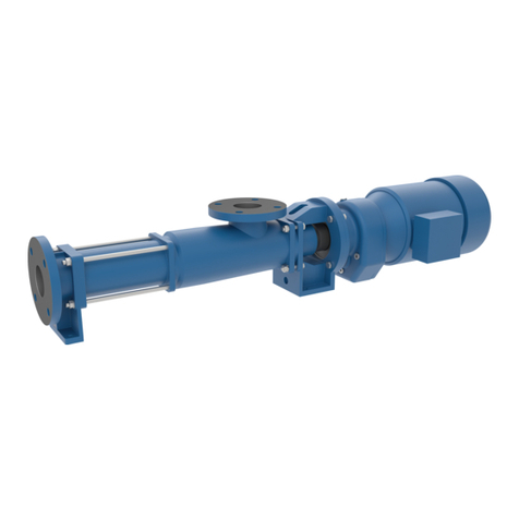
Three–screw pumps in flange design form, with a
double–threaded driving spindle and two double–
threaded idler spindles, enclosed in a rotor housing
with narrow running clearance.
4.1.1 Bearing and lubrication
By a pre–mounted, greased groove ball bearing to
DIN 625, not regreasable, with sealing washers on
both sides and lifetime grease filling.
4.1.2 Shaft seal
SMechanical seal, design 8.6
(Standard for dry installation):
Uncooled, maintenance–free mechanical seal of
the unbalanced type.
Materials of the mechanical seal:
Rotating seal ring: Silicon carbide
Stationary seal ring: Silicon carbide
Auxiliary gaskets: Viton
Spring: CrNiMo steel
Metal parts: CrNiMo steel
Swithout shaft seal, design Q
(Standard for wet installation)
4.1.3 Pipeline and auxiliary connections
For execution, branch positions and dimensions of all
connections, see order–specific installation drawing.
4.1.4 Pressure relief valve
For safety reasons, screw pumps must generally be
equipped with a pressure relief valve.
Mostpumpsarealreadyequippedwithapressurerelief
valvewhen theyleave the factory. The standardtrigger
pressure of this valve is approximately 10% above the
operating pressure.
Pumpsthataresuppliedwithoutapressurereliefvalve
must be provided with a suitable safety valve by the
customer. The safety valve must be fitted in the dis-
chargepipelinebetweenthepumpandthefirstshut–off
device.
4.2 Mode of operation
Through the suction connection, the fluid is conveyed
into the suction chamber of the pump. From there the
fluid flows into the spindle chambers, which are
constantly formed by the rotary motion at the spindle
end on the suction side. By the translatory rotary
motion,thechambersfilledwiththe fluidmovefromthe
suction side to the outlet side. During this process the
closed chamber volume does not change. At the
spindle end on the outlet side the chamber opens
towards the delivery chamber. The fluid is steadily
pushed out into the delivery chamber from where it is
transported, through the pressure connection, into the
pressure pipeline.
The axial thrust acting on the faces of the profile flanks
on the outlet side is hydraulically balanced by an
appropriate dimensioning of the compensating piston
of the driving spindles and the compensating journals
of the idler spindles. Thus the bearing is relieved of the
hydraulic axial thrust.
The idler spindles are hydraulically driven by means of
appropriate dimensioning of the spindles. The torque
resulting from the friction is transmitted via the profile
flanks.
Asaresultoftheconstantchambervolumethemedium
inside the pump is transported, almost entirely free of
turbulence and squeezing, from the suction side to the
outlet side.
The structural design and mode of operation of the
screw pump ensure a very low noise level and an
almost pulsation–free delivery.
4.3 Construction of the pump aggregate
4.3.1 Drive
Thepumpscanbe directlycoupledwith electricmotors
of the most varied designs, or any other prime movers.
In most cases, surface–cooled three–phase squirrel
cageinduction motorsare usedas drivingmotors, type
IMV1,classofprotectionIP54toIECstandard,classB
insulation, outputs and speeds to DIN 42 677.
The exact motor data are to be found on the order data
sheet.
4.3.2 Shaft coupling and contact protection
Powertransmissioniseffectedviaaflexiblecouplingto
DIN 740. Additional radial forces must not act on the
driving spindle.
Protection against accidental protection to EN 809 is
provided where a pump bracket or fitting lantern is
supplied as part of the product package.
According to accident prevention regulations, the
pump must only be operated with a protection
against accidental contact as per EN 809.
Ifnocontactprotectionisprovided,itmust be attached
by the operator.
4.3.3 Pump bracket/Foot angle
Pump brackets and foot angles are available for
horizontal or vertical mounting with V1 motors.
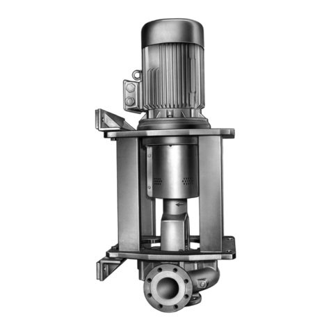
4.3.4 Fitting lantern
Fitting in the fluid tank is enabled by using fitting
lanterns.
Note: A fitting lantern attached by the operator must
have bore holes to drain off the fluid medium.
4.3.5 Base plate/Foot angle
Suitable foot angles are available for mounting of the
flange pump for horizontal assembly with B3 motors.
Base plates can be provided in cast or steel design.
