manuals.online logo
Brands
  1. Home
  2. •
  3. Brands
  4. •
  5. Allweiler
  6. •
  7. Water Pump
  8. •
  9. Allweiler SLTP Series Manual

Allweiler SLTP Series Manual

ALLWEILER a
1. General
1.1 Application and range of utilization
The eccentric screw pumps are self-priming, rotary
positive-displacement pumps for handling and dosing
low to high-viscosity, neutral or aggressive, pure or
abrasive, gaseous liquids or liquids which tend to froth,
even with fibre and solids contents.
BThe range of utilization is to be taken
from the order data sheet.
1.2 Performance data
The exact performance data applying to the pump are
to be taken from the order data sheet and are engra-
ed on the name plate.
1.3 Warranty
Our liability for shortcomings in the supply is laid down
in our delivery conditions. No liability will be undertaken
for any damages caused by non-compliance with the
operating instructions and service conditions.
If at any later date the operating conditions happen to
change e.g. different liquid pumped, speed, viscosity,
temperature or pressure conditions), it must be checked
by us from case to case and confirmed, if necessary,
whether the pump is suited for these purposes. In case
no special agreements were made, pumps supplied by
us may, during the warranty period, be opened or varied
only by us or our authorized contractual service stati-
ons; otherwise, our liability for any defects will cease.
1.4 Testing
Prior to leaving our factory, all pumps are subjected to a
leakage and performance test. Only properly operating
pumps leave the factory achieving the performances
assured by us. Thus, compliance with the following ope-
rating instructions ensures proper operation.
2. Safety
These operating instructions contain basic hints to be
observed in case of installation, operation and mainte-
nance. Therefore, prior to mounting and commissioning,
these operating instructions must by all means be read
by the fitter as well as the pertinent expert person-
nel/customer and must always be available at the place
of installation of the machine/plant.
Not only are the general safety hints listed under this
main item „Safety“ to be observed, but also the special
safety hints such as for private use added to the other
main items.
1
2.1 Marking of hints in the operating instructions
The safety hints contained in these operating instruc-
tions which, in case of non-compliance, may cause dan-
ger to personnel, are particularly marked with the gene-
ral danger symbol
!
Safety sign
according to DIN 4844–W9
in case of warning against electric voltage with
$
Safety sign
according to DIN 4844–W8
For safety hints, non-compliance with which may cause
dangers to the machine and its functions, the word
B
is added.
Hints directly attached to the machine such as
– Directional marker
– Sign for fluid connections
must by all means be observed and maintained in com-
pletely legible condition.
2.2 Personnel qualification and personnel training
The personnel for operation, maintenance, inspection
and mounting must have the corresponding qualifica-
tion for these operations. Range of liability, competence
and the supervision of the personnel must be exactly
controlled by the customer. If the personnel do not have
the required knowledge, same must be trained and
instructed. If required, this may be effected by the
manufacturer/supplier on behalf of the machine cus-
tomer. In addition, it must be ensured by the customer
that the contents of the operating instructions are fully
understood by the personnel.
Operating and Maintenance Instructions
with Dismounting and Mounting Instructions
Eccentric Screw Pumps
Series SLTP, SETP, SNTP, SLTBP, SETBP, SNTBP
Operating data of pump according to order data sheet
Job No.: Pump Ident No.:
Machine No.: Pump Type:
2
2.3 Dangers in case of non-compliance with the safety
hints
Non-compliance with the safety hints may result in dan-
ger not only to persons, but also to environment and
machine. Non-compliance with the safety hints may
lead to the loss of any claims for damages.
In detail, non-compliance may, for example, entail the
following dangers:
– Failure of important functions of the machine/plant
– Failure of specified methods for maintenance and
servicing
– Danger to persons by electrical, mechanical and
chemical influences
– Danger to the environment by leakage of dangerous
substances
2.4 Responsible working
The safety hints mentioned in these operating instruc-
tions, the current national rules for the prevention of
accidents as well as any internal working, operating and
safety regulations of the owner must be observed.
2.5 Safety hints for the user/operator
– If hot or cold machine parts lead to dangers, these
parts must be protected against accidental contact
at the site.
– Protection against accidental contact for moving
parts must not be removed when the machine is in
operation.
– Leakages e.g. of the shaft seal) of dangerous mate-
rials to be handled e.g. explosive, toxic, hot) must be
discharged so as not to result in danger to persons
and the environment. Legal stipulations are to be
observed.
– Dangers by electrical energy are to be excluded for
details with regard hereto, please refer e.g. to the
regulations of the VDE and the local energy supply
associations).
2.6 Safety hints for maintenance, inspection and mount-
ing operations
The customer shall see to it that all maintenance, ins-
pection and mounting operations are performed by aut-
horized and qualified expert personnel who have suffi-
ciently informed themselves by thoroughly studying the
operating instructions.
Basically, operations at the machine must be performed
during standstill only. The mode of operation for stop-
ping the machine described in the operating instruc-
tions must by all means be observed.
Pumps or aggregates handling noxious liquids must be
decontaminated.
Immediately upon completion of the operations, all
safety and protective devices must be mounted and
made operational again.
Prior to restarting, the items listed in Section „6.1 Prepa-
ration for Starting“ are to be observed.
2.7 Arbitrary reconstruction and spare parts production
Reconstruction of or changes to the machine are only
admissible after consultation with the manufacturer. Ori-
ginal spare parts and accessories authorized by the
manufacturer serve safety purposes. The use of other
parts may cancel the liability for the consequences
resulting therefrom.
2.8 Inadmissible modes of operation
The operating safety of the machine supplied is only
ensured with due application according to Section 1 –
General – of the operating instructions. The limit values
given in the data sheet must by no means be exceeded.
3. Transportation and intermediate storage
3.1 Packing
The symbols applied to the packing must be observed.
During transportation and storage, suction side and
auxiliary connections of the pump must be closed with
plugs. During installation of the pump aggregate, the
plugs must be removed.
3.2 Transportation
Due to their weight, eccentric screw pumps and all
pump aggregates are transported to the place of instal-
lation by means of a lifting appliance.
The sling ropes must be placed around the pump and/or
the pump aggregate so that when being lifted, they are
in exact balance.
!Crane installation and the sling ropes must be suffi-
ciently sized. The sling ropes must not be fixed to the
suspension eyes of the motor.
3.3 Preser ation and storage of eccentric screw pumps
Please refer to our document VM 2102GB/...
4. Description
4.1 Structural design
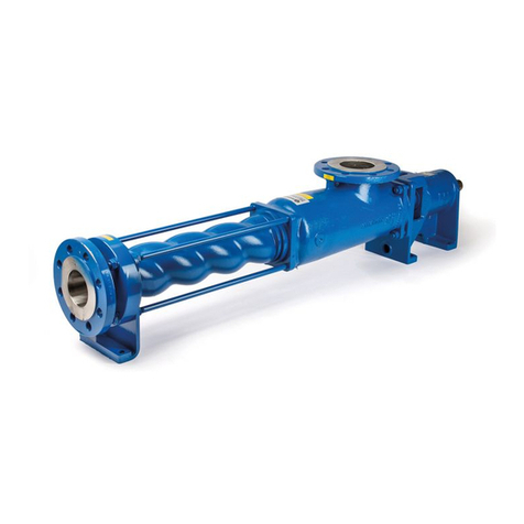
Self-priming, single or two-stage eccentric screw pump.
Rotor and stator are the conveying elements. Via the
hollow shaft and/or drive shaft and the coupling rod, the
drive torque is transmitted onto the rotor.
Discharge casing, stator and suction cover are held
together by external casing connecting screws tie
rods).
The shaft sealing or mechanical seal housing are arran-
ged between discharge casing and lantern and/or bea-
ring bracket.
4.1.1 Bearing and lubrication
Coupling rod on both sides with pin joints encapsulated
liquid-tight. Lubrication by joint oil.
Bearing of the drive/hollow shaft is in the reinforced
bearings of the drive and/or in the bearing bracket by
grease-lubricated axial and grooved ball bearings andor
cylindrical roller bearings.
4.1.2 Shaft seal
By uncooled or cooled stuffing box or by uncooled or
cooled, maintenance-free, non-balanced, single or
double-acting mechanical seal.
4.1.3 Dimensions/branch position/flanges
The dimensions of the pump and/or pump aggregate,
the branch position and flange dimensions are to be
taken from the tables of dimensions.
4.2 Mode of operation
Self-priming, rotary positive-displacement pump, the
conveying elements of which are the rotating eccentric
screw rotor) and the fixed stator. Both meet in the
cross-section at two points each which, regarded over
the length of the conveying elements, form two sealing
lines. The contents of the tight chambers formed as the
rotor rotates are shifted axially and completely contin-
uously from the suction to the discharge side of the
pump. There is no turbulence despite the rotor rotation.
The constant chamber volume excludes squeezing thus
ensuring an extremely gentle low-pulsation delivery.
4.3 Aggregate construction
4.3.1 Dri e
By non-explosion-proof or explosion-proof electric mo-
tors, geared motors or variable-speed geared motors.
Other drive variants e.g. via V-belt) are possible.
Series SLTP, SETP, SNTP, SLTBP, SETBP, SNTBP ALLWEILER a
3
4.3.2 Shaft coupling and protection against accidental con-
tact
Shaft coupling according to DIN 740.
A protection against accidental contact according to
DIN 24 295 is attached as soon as the scope of supply
comprises pump, coupling housing, shaft coupling and
drive.
!According to the rules for the pre ention of accidents,
the pump may be operated only with a protection against
accidental contact according to DIN 24 295.
If a protection against accidental contact is not sup-
plied, it must be installed by the customer.
5. Installation/mounting
5.1 Installation
The pumps must be installed vertically with drive up-
wards.
Depending upon the immersion depth and pump speed,
it may be necessary to provide a supporting device for
the suction-side operation of the pump.
5.2 Foundation
The foundation design depends on the size of the pump
and/or the pump aggregate and the local installation
conditions. For exact data on the pump and aggregate
dimensions, please refer to our tables of dimensions.
The foundation may be designed as concrete founda-
tion or load-carrying foundation frame, for example of
the steel type.
All foundation designs are subject to the following: The
foundation must be designed so that it can take the
weight of the pump aggregate on the entire surface.
5.3 Assembly of pump and dri e
The aggregate being completed at the place of service
only, the coupling must be assembled as follows:
1. Cover pump and drive shaft end with a filmy coat of
molybdenum disulfite e.g. Molykote), and insert keys.
2. By means of a mounting device, push pump and
motor-side coupling halves on until the shaft end is
flush with the coupling hub.
If no mounting device is available, heating of the cou-
pling halves to approx. 100hC without rubber buf-
fers) facilitates mounting.
3. By means of a grub screw according to DIN 916, fix
coupling halves axially.
4. When assembling pump and motor, geared motor
and/or variable-speed gear it must be ensured that
the coupling halves are accurately aligned. Depend-
ing upon the size of coupling, the distance between
the coupling halves must be 2–8 mm.
!5. Mount protection against accidental contact accor-
ding to DIN 24295.
5.4 Dri e by V-belt dri e
In case of a V-belt reduction from the drive to the pump,
make sure that the two V-belt pulleys are aligned in
parallel.
The V-belt pulleys must be pushed onto the shaft ends
as far as possible. It must be possible to regulate the
tension of the V-belts sufficiently by means of a motor
rocker or by means of tensioning rails. They must be
slightly retightened after a short running-in period.
BExcessi e tensioning will destroy the
anti-friction bearings of the pump. Our
separate instructions – V-belt drive – VM 706.0001 GB/
Ident No. 133586 must be complied with.
5.5 Laying of pipelines
5.5.1 Nominal diameters
The nominal diameter of the suction line should be
designed according to the nominal pump branch dia-
meter. In case of considerable deviations please contact
the factory.
5.5.2 Supports and flange connections
By way of the flange connections, the pipelines must be
connected to the pump, stress-free. They must be sup-
ported close to the pump and should allow of easy scr-
ewing to avoid deformations. After the screws have
been slackened, the flanges must neither be inclined
nor springy nor rest on top of one another under pres-
sure. Any thermal stresses that may occur at the pipe-
lines must be kept away from the pump by taking appro-
priate measures, e.g. by the installation of compen-
sators.
5.5.3 Cleaning of tanks prior to attachment
Prior to mounting the pump, the suction-side tanks must
by all means be flushed and/or cleaned.
Items left over from assembly operations, e.g. screws,
nuts, welding beads, pieces of steel etc. will destroy the
pump internals. Any guarantee claims will expire if and
when damages are caused by such items.
5.6 Laying of auxiliary pipelines for additional facilities
All auxiliary pipelines for the supply of the shaft seal and
the double shell casing, if any, for heating and cooling of
the shaft sealing housing are to be connected, stress-
free and sealing.
In case of double-acting mechanical seal design: G08,
G09), the lines for the sealing liquid are to be laid with
the largest possible flow cross section. The sealing
liquid outlet is at the highest connection of the mecha-
nical seal housing.
The flow direction of the flushing and sealing liquid is
shown by means of arrows in the sectional drawings.
In order to ensure automatic ventilation, the lines must
be laid continuously ascending, short and promoting
easy flow.
Air bag formation and gas bubble formation are to be
avoided, if required, ventilation connections must be
provided. The heating/cooling liquid outlet must be con-
nected at the highest connection of the double shell
casing, if any.
5.7 Safety and control de ices
5.7.1 Pressure gauge
A pressure gauge must be connected to the discharge
line.
5.7.2 Safety element in the discharge line
If a shut-off element is fitted in the discharge line or if
there is a possibility of the discharge line becoming
blocked, a safety element must be provided. For exam-
ple: by-pass with built-in relief valve, bursting disk,
motor protection switch, etc.
!Eccentric screw pumps are positi e-displacement
pumps and can theoretically generate an infinitely high
pressure.
With the discharge line closed, e.g. by clogging or by
incidental closing of a al e, the pressure generated by
the pump may reach a multiple of the admissible pres-
sure of the plant. This may, for example, lead to the
bursting of lines which must be absolutely a oided
especially when handling dangerous products. Thus,
appropriate safety de ices must also be installed in
the plant (e.g. pressure switches).
Series SLTP, SETP, SNTP, SLTBP, SETBP, SNTBP ALLWEILER a
4
5.8 Electric connections
$Connection of the power supply cables of the drive
motor must be effected by an electrical expert accord-
ing to the switching diagram of the motor manufacturer.
For these purposes, the current VDE regulations and the
regulations of the local energy supply association are to
be observed.
Danger by electrical energy must be excluded.
6. Starting/stopping
6.1 Preparation for starting
6.1.1 Filling the tanks with liquid
BDo not allow the pump to run when dry!
Even a few revolutions without liquid
can damage the stator. For this reason, the minimum
covering shown in the tables of dimensions must be
observed.
6.1.2 Switching in the additional facilities for shaft seals (if
pro ided)
If the pumps are charged with a sealing/quench liquid,
the stop valves, prior to initial start-up of the pump, must
be opened and set to the pressures listed below.
– Supply of the stuffing box with flushing or sealing
liquid Designs P02, P12, P03, P13, P04 and P14).
Note: For maintaining their function, stuffing boxes
with flushing or lantern rings require a flushing/seal-
ing liquid.
The required flushing and/or sealing liquid pressure
in case of pumps with stuffing box is for stuffing box
designs
P02/P12 = 0.1 up to 0.5 bar above internal
discharge casing pressure)
P03/P13 = 0.5 bar above internal
discharge casing pressure)
P04/P14 = 0 up to 0.5 bar
For flushing and sealing liquid, please refer to Sec-
tion 6.1.3 below).
– Supply of the single-acting, non-balanced mecha-
nical seal with throttled sealing liquid outlet
Designs G04 ... G07)
Note: For maintaining their function, these mechani-
cal seals require a flushing liquid which dissipates the
generated frictional heat and limits the penetration
of the liquid to be pumped into the sealing chamber.
The required flushing liquid pressure is 0.1 up to 0.5
bar above the internal discharge casing pressure for
flushing liquid, please refer to Section 6.1.3 below).
– Supply of the double-acting non-balanced mechani-
cal seal Designs G08, G09)
Note: For maintaining their function, these mechani-
cal seals require a sealing liquid which serves to dis-
sipate the generated frictional heat and to avoid
penetration of the liquid to be pumped into the seal-
ing gap.
BPrior to each start-up, the circulation
of the sealing liquid must be ensu-
red. The sealing liquid pressure must be approx. 1.5
to 2 bar above the pressure in the discharge casing.
The flow rate must be regulated so that the outlet
temperature of approx. 60 hC is not exceeded and is
at least 30 K below the boiling temperature at opera-
ting pressure for sealing liquid, please refer to Sec-
tion 6.1.3 below).
6.1.3 Quality and properties of the flushing/sealing liquid
BAny liquid may be used as sealing/
flushing liquid in consideration of the
corrosion resistance of all contacted parts and the
consistency with the medium to be sealed. The liquid
must be free from solids, must not tend to sedimentati-
ons, should have the highest possible boiling point as
well as a good heat conductivity and low viscosity. Clean
water of low hardness meets these demands to a high
degree.
6.1.4 Switching in the additional facility for heating or cool-
ing the shaft sealing housing (double shell housing)
If the pumps are equipped with this additional facility,
any and all stopping devices for heating or cooling
systems must be opened. The below-mentioned pres-
sure and temperature limits must be observed.
– Supply of the cooled or heated shaft sealing hous-
ing (double shell housing) with appropriate liquid
medium
!Only liquid media may be used as heating or cooling
liquid in consideration of the corrosion resistance of
all contacted parts.
The maximum heating or cooling liquid pressure is
10 bar.
The maximum heating temperature must not exceed
180hC, and the cooling temperature not fall below
–40hC.
Note: For the design temperature, please refer to the
order data sheet.
6.1.5 Break-away of the pump
When starting up for the first time or after a longer shut-
down period, make sure that the pump can be easily tur-
ned by the drive motor. If this is not readily possible, e.g.
due to a high degree of adhesion between the rotor and
stator when brand new, movement can be assisted by
using a suitable tool in the key area of the drive shaft
and/or at the hollow shaft behind the shaft seal.
BWhen doing so, the drive/hollow shaft
must not be damaged.
6.1.6 Control of the sense of rotation
The sense of pump rotation is clockwise, looking from
the drive towards the drive shaft.
BThe sense of pump rotation must corre-
spond to the directional marker „n“ in
the pump name plate. Wrong sense of rotation may
result in damages to the pump. For a control of the
sense of rotation, the motor on/off switch is to be tou-
ched only briefly.
6.2 Starting
6.2.1 Start-up
All shut-off elements on the discharge side must be
opened before starting up.
6.2.2 Dri e
Switch motor in.
BConsider product-specific particulari-
ties of the drive. Please refer to the
operating instructions of the dri e manufacturer.
6.2.3 Checking the deli ery alues
After the drive has reached its operating speed, the
pump outlet pressure must be checked via the pressure
gauge.
The motor must not be overloaded. The power con-
sumption can be checked by means of an ammeter. In
this connection, temperature and viscosity of the liquid
to be handled must be checked. The values read must
be checked against the order data sheet and/or accep-
tance report.
Series SLTP, SETP, SNTP, SLTBP, SETBP, SNTBP ALLWEILER a
Bearing greases
For the lubrication of the anti-friction bearings it is
recommend to use the below-listed bearing greases or
equivalent. The order of producers is no quality ranking.
Producer Brand name
ARAL HL 3
BP BP ENERGREASE LS 3
CALTEX CALTEX MULTIFAX 2
ESSO BEACON 3
GULF GULFCROWN GREASE No. 2
GULFCROWN GREASE No. 3
MOBIL-OIL MOBILUX GREASE FETT 3
SHELL SHELL ALVANIA FETT 3
SKF ALFALUB LGMT 3
VALVOLINE VALVOLINE LB 2
If the listed bearing greases are not available, we recom-
mend in any case a multi-purpose grease on lithium basis.
Grease mixture with grease grades of different basic
oils and thickeners leads to a reduction of the lubricat-
ing properties and must therefore be avoided.
The table under Section 7.1.2.6 below shows the alloca-
tion of the pump size to the grease quantity in grams.
Relubrication period of bearings
Every 4000 operating hours, the bearings must be re-
lubricated.
Relubrication
Relubrication is effected by means of the grease nipples
119). Relubrication must be repeated for such a period
of time until the used grease emerges at the grease
quantity controller 138) or lip seal 120). The used
grease must be scraped off.
7.1.2.3 Shaft seal
Shaft sealing is either via a stuffing box or a mechanical
seal.
xStuffing box
Increased leakages, if any, at the stuffing box during the
first operating hours normally disappear automatically
during the running-in period.
If necessary, slightly tighten hexagon nuts 202) at the
gland 203).
Please note that the stuffing box must be slightly lea-
king. This causes dissipation of the frictional heat gene-
rated at the sealing surface.
If the leakage losses increase excessively, and if leak-
age cannot even be reduced by repeated slight tigh-
tening of the hexagon nuts 202), the packing rings have
lost their elasticity of shape and must be replaced.
– Dismounting the old packing rings and cleaning the
shaft sealing housing
Following the pressure relief of the pump and after
removal of the gland, the old packing rings can be
removed. A packing puller with flexible shaft serves
as tool. Thereafter, the stuffing box chamber and the
drive shaft and/or hollow shaft must be carefully cle-
aned within the area of the packing rings. Worn drive
shafts/hollow shafts and/or shaft wear sleeves must
be replaced refer to the Dismounting and Mounting
Instructions).
5
6.2.4 Dry run protection
After start-up, it must be ensured that the flow of liquid
on the suction side is never completely interrupted in
order to prevent the pump from running dry.
BObserve minimum covering.
6.3 Stopping
6.3.1 Shut-down
Switch motor off.
6.3.2 Measures in case of a longer shut-down period
If a longer shut-down period is projected and there is a
danger of frost, the pump must be drained. Thereafter,
the pump must be preserved please refer to Section
3.3. above).
7. Maintenance/ser icing
7.1 Maintenance
– For maintenance and service operations, the details
listed under Section 2. Safety are to be observed.
Regular control and maintenance of the pump and
drive will extend the service life.
7.1.1 General control
1. Do not allow the pump to run when dry.
2. The drive motor must not be overloaded.
3. Check discharge lines for tightness.
4. During operation, an installed stuffing box must be
slightly dripping.
An installed mechanical seal must not have any
heavy leakage.
5. Observe pressure and temperature monitoring instru-
ments, and check against the order data sheet and/or
acceptance report.
6. Observe additional facilities such as flushing or seal-
ing of the shaft seal, if provided.
7. Observe additional facilities for heating or cooling of
the shaft sealing housing, if provided.
7.1.2 Maintenance of components
7.1.2.1 Joints of the coupling rod
The joints of the coupling rod are lubricated with All-
weiler Spezialgelenköl Type B or Öl ET 1510 ISO 460 of
Tribol Lubricants GmbH, Mönchengladbach, Germany; if
the pumps are used for foodstuffs, with Allweiler Spe-
zialgelenköl Type BL or Öl 1810/460 of Tribol Lubricants
GmbH, Möchengladbach, Germany.
BOther lubricants were not tested by us
and can, therefore, not be recommend-
ed by us!
The joints are lubricated for life. However, if the pump
must be opened for any other purposes, we recommend
to check the cover sleeve for tightness and to change
the joint oil after 8,000 working hours. The table under
Section 7.1.2.6 below shows the allocation of the pump
size to the oil quantity in cubic centimeters. For the
change of the joint oil, please refer to the Dismounting
and Mounting Instructions.
7.1.2.2 Bearing of the dri e shaft and lubrication of the bearing
(if pro ided)
The bearing of the drive shaft in the bearing bracket is
by regreasable axial and grooved ball bearings and/or
cylindrical roller bearings.
Series SLTP, SETP, SNTP, SLTBP, SETBP, SNTBP ALLWEILER a
6
– Mounting the packing rings
BIn principle, only such packing rings
are to be installed which correspond
to the required operating conditions of the pump.
For the dimensions and necessary quantity of the
pre-pressed packing rings and ring cuts and/or cut-
ting lengths, please refer to the table Section 7.1.2.6
below.
For cutting purposes, we recommend the straight
cut perpendicular to the shaft. In order to achieve a
gap-free parallel position of the cut ends when clos-
ing the packing ring, the cutting angle should be
approx. 20hto both cutting ends please refer to
Figure 1 below).
Figure 1: Cutting of packing rings
Pre-pressed packing rings or ring blanks must be care-
fully untwisted axially and radially to such a degree only
that they can just be pushed over the shaft. Bending-up
the rings may result in damage by breaking.
During installation in the packing chamber, the packing
rings must be carefully re-bent into angular shape.
During this process, the kerfs must be set off by 90h. By
means of the gland, each ring must be individually pus-
hed into the stuffing box chamber with the cut ends
foremost. Lantern ring or flushing ring must be installed
consistently.
BPointed items must never be used for
these purposes as there is a danger of
shaft damage and deformation of the packing materials.
– Commissioning of the stuffing box after re-packing
Prior to commissioning, the stuffing box must be only
slightly tightened. During pump starting, 50 to 200
drops in a minute are admissible as seepage quan-
tity.
During the starting process of approx. 30 minutes, a
minimum leakage of 2 to 20 drops in a minute must
be set by gradually and evenly tightening the gland
203) by means of the hexagon nuts 202).
BDuring this process, the stuffing box
temperature must not rise abnor-
mally. Approx. 20 to 60hC above the temperature of
the liquid pumped are admissible. In case of a sud-
den temperature rise, the gland must be immediately
slackened and the running-in procedure repeated.
The seepage can be drained through the threaded
hole provided in the fastening flange.
!Personal injuries and environmental damages result-
ing from the leakage of dangerous materials must be
excluded.
xMechanical seal
Non-balanced mechanical seals are used in any mate-
rial combinations and models. The mechanical seal is
maintenance-free.
In case of heavy leakage due to wear, the mechanical
seal must be replaced please refer to the Dismounting
and Mounting Instructions).
BAs dry running of a mechanical seal
must be avoided, the pump, if provided,
must be started with the additional facilities switched in
please refer to Section 6.1.2 above).
7.1.2.4 V-belt dri e
Please refer to our maintenance instructions for V-belt
drive with tensioning device VM 706.0001 GB – Ident
No. 133586.
7.1.2.5 Dri e motors and ( ariable-speed) gears
Please refer to the manufacturers’ operating and main-
tenance instructions.
Series SLTP, SETP, SNTP, SLTBP, SETBP, SNTBP ALLWEILER a
7
Number and Dimensions of Oil Grease
dimensions the packing quantity quantity
Series of packing rings rings as blank cm3/joint g/bearing
in designs P01
and P11 †
SLTP SETP SNTP SLTBP SETBP SNTBP for ring blanks LMxS T
99.1 50.1 50.2 25.1 5 pieces 127,7 x 08010 0160
25.2 Ø 46/30 x 8
99.1 50.1 50.2 25.1 5 pieces 144,5 x 08010 –
25.2 Ø 51/35 x 8
199.1 100.1 100.2 50.1 5 pieces 144,5 x 08018 0250
50.2 Ø 51/35 x 8
199.1 100.1 100.2 50.1 6 pieces 171,4 x 08018 –
50.2 Ø 59/43 x 8
400.1 200.1 200.2 100.1 5 pieces 168,1 x 08037 0400
100.2 Ø 58/42 x 8
400.1 200.1 200.2 100.1 5 pieces 211,8 x 10 037 –
100.2 Ø 73/53 x 10
720.1 380.1 380.2 550.1 200.1 5 pieces 208,4 x 10 052 0650
200.2 Ø 72/52 x 10
720.1 380.1 380.2 550.1 200.1 5 pieces 252,1 x 12 052 –
200.2 Ø 87/63 x 12
1560.1 750.1 750.2 1000.1 380.1 5 pieces 252,1 x 12 087 1050
380.2 Ø 87/63 x 12
1450.1 1450.2 750.1 6 pieces 302,5 x 12 169 2000
750.2 Ø 102/78 x 12
2700.1 1450.1 6 pieces 366,4 x 14 290 3000
1450.2 Ø 123/95 x 14
5000.1 2700.1 6 pieces 366,4 x 14 565 2000
Ø 123/95 x 14
7.1.2.6 Packing ring dimensions (to Section 7.1.2.3), lubricant quantities for joints (to Section 7.1.2.1)
and bearing (to Section 7.1.2.2).
Pump
size
† in case of shaft seal designs P02...P04, P12 ... P14, the quantity is reduced by 1 piece
8
7.2 Ser icing (Dismounting and Mounting Instructions)
General
On request, trained service engineers will be at your dis-
posal for mountings and repairs.
In case of repairs performed by the customer’s own per-
sonnel or our trained mechanics, it must be ensured
that the pump is completely empty and clean.
This applies in particular to pumps which, in case of
repair, are sent to our factory or to one of our contrac-
tual repair shops.
In protection of our staff and for reasons of environmen-
tal protection, we have to refuse to accept for repair any
pumps filled with liquid pumped. Otherwise, we will have
to charge the customer/operator with the costs for an
ecologically acceptable waste disposal.
In case of repair of pumps operated with dangerous
materials †and/or liquids harmful to the environment,
the customer/operator must advise hereof his own and-
or our local mounting personnel or, in case of return, our
factory and/or contractual service shop of his own
accord. In such a case, evidence of the liquid handled,
e.g. in the form of a DIN safety data sheet will have to be
presented to us when requesting a service engineer.
†Dangerous materials are:
– Toxic substances
– Substances detrimental to health
– Caustic substances
– Irritants
– Explosive materials
– Fire-promoting, highly, easily and normally inflam-
mable materials
– Carcinogenic substances
– Foetopathic substances
– Genes-changing substances
– Substances which are dangerous to human beings in
any other way
When working locally, the customer’s own and/or our
mounting personnel must be referred to dangers which
may be caused in connection with repairs.
The most important dismounting and mounting opera-
tions are described in these instructions. The mounting
steps described in the individual sections must be con-
sistently observed.
7.2.1 Dismounting the eccentric screw pump
Prior to commencing the dismounting, the following
operations must be performed:
– Disconnect power supply cable from the motor.
Motor must not be capable of being started.
– All shut-off elements in the discharge line must be
closed.
– Dismount discharge line and all auxiliary pipelines.
– Loosen screws at the fastening flange, and screw out.
7.2.1.1 Dismounting the stator
– Drain the liquid to be pumped from the discharge
casing.
Note: Use collecting tank.
– Remove hexagon nuts 609) and washers 610) from
the tie rods 611).
– Withdraw suction cover 505).
– Remove tie rods 611).
– Withdraw stator shell 516) and O-ring 517).
– Withdraw stator 402) from rotor 401).
Note: In case of stiffness, turn stator 402) simulta-
neously by means of chain tongs. For these purpo-
ses, fix hollow shaft 125) and/or drive shaft 118).
7.2.1.2 Dismounting the rotor and rotor-side joint
Dismounting of the rotor and the rotor-side joint is
effected following the dismounting of the stator 402).
Please refer to Section 7.2.1.1 above.
– Dismount vent line for mechanical seal 224).
– Remove hexagon nuts 618) and spring ring 619) as
well as hexagon screws 617).
– Withdraw discharge casing 504) over the rotor
401). In doing so, see to it that the precision-
machined rotor is not damaged.
– Remove gasket for discharge casing 511).
– Cut buckle on clamping band 306) with a metal saw,
and with a screw driver, press out to both sides.
Remove clamping band 306) from the cover sleeve
308) please refer to Figure 2 below).
Figure 2: Removal of the clamping band.
!
– By means of a screw driver, lift cover sleeve 308)
and withdraw axially towards the coupling rod 307).
– Collect oil filling in a tank.
– Drive retaining sleeve 304) over the collar of the
coupling rod 307). In doing so, do not deflect coup-
ling rod 307) please refer to Figure 3 below).
Figure 3: Dismounting the retaining sleeve.
– Eject coupling rod pin 301).
– By means of a brass ejector, drive out the two bushes
for coupling rod pin 303) by one half. For these pur-
poses, incline coupling rod 307) please refer to
Figure 4 below).
Series SLTP, SETP, SNTP, SLTBP, SETBP, SNTBP ALLWEILER a
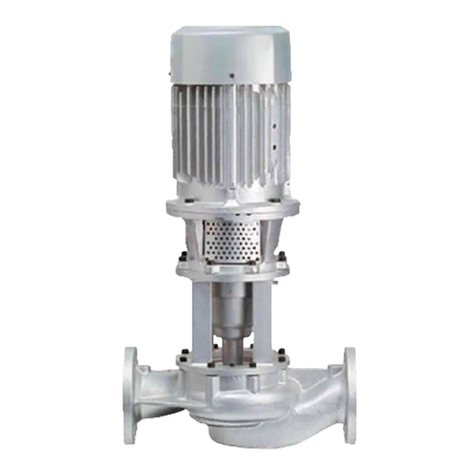
Figure 4: Dismounting the bushes for coupling rod pin.
– Remove rotor 401) from the coupling rod 307).
– Press coupling rod bush 302) out of the coupling rod
307).
– By means of a brass mandrel, completely drive bush
for coupling rod pin 303) out of the rotor 401).
7.2.1.3 Dismounting the coupling rod and the dri e-side joint
Dismounting of the coupling rod and the drive-side joint
is effected following the dismounting of the stator 402)
and the rotor 401). Please refer to Sections 7.2.1.1 and
7.2.1.2 above.
– Dismount drive-side joint as described under Sec-
tion 7.2.1.2 above.
– Withdraw coupling rod 307) from the drive shaft
118) and/or hollow shaft 125).
– Press coupling rod bush 302) out of the coupling rod
307).
– By means of a brass mandrel, completely drive bush
for coupling rod pin 303) out of the drive shaft 118)
and/or hollow shaft 125).
7.2.1.4 Dismounting the shaft seal and hollow shaft (series
SLTBP, SETBP and SNTBP)
Note: In case of pumps with shaft seal by stuffing box,
the packing rings can be exchanged without dismount-
ing the hollow shaft, as described under Section 7.1.2.3
above. Dismounting of the hollow shaft is required whe-
never the pump is equipped with a mechanical seal. In
case of damages to the hollow shaft within the area of
the shaft seal, the pump must also be dismounted, as
described hereinafter.
– Dismount stator 402) please refer to Section 7.2.1.1
above).
– Remove hexagon nut 618) and spring ring 619) as
well as hexagon screw 617).
– Withdraw discharge casing 504) over the rotor 401).
In doing so, see to it that the precision-machined
rotor is not damaged.
– Remove gasket for discharge casing 511).
– Eject retaining pin 123) from hollow shaft 125).
– Pull hollow shaft 125) with all parts of the shaft seal
out of the lantern 112).
xDismounting the stuffing box
– Remove hexagon nut 202) and gland 203).
– Pull shaft sealing housing 204) from the hollow shaft
125).
9
– Remove stuffing box packing 207) in case of model
P02 including flushing ring 208), and in case of
models P03 and P04 including lantern ring 209) from
shaft sealing housing 204).
xDismounting the mechanical seal, single-acting
– Withdraw mechanical seal housing 214) with atmos-
phere-side stationary seal ring of the mechanical
seal 219) from the hollow shaft 125).
Note: Particularly see to it that the casing with sta-
tionary seal ring of the mechanical seal is withdrawn
concentrically and not canted to avoid damages to
the stationary seal ring.
– Press stationary seal ring of the mechanical seal and
O-ring out of the mechanical seal housing 214). See
to uniform pressure distribution.
– Drive out locking pin 220).
– Undo grub screws, if provided, in the rotating part of
the mechanical seal 219), and withdraw mechanical
seal from the hollow shaft 125).
BBefore undoing the grub screws,
mark or measure the position of the
mechanical seal on the hollow shaft. Do not push
O-rings over the pressure marks caused by the
screws!
7.2.1.5 Dismounting the shaft seal and dri e shaft with bearing
(series SLTP, SETP and SNTP)
Note: In case of pumps with shaft seal by stuffing box,
the packing rings can be exchanged without dismount-
ing the drive shaft, as described under Section 7.1.2.3
above. Dismounting of the drive shaft is required when-
ever the pump is equipped with a mechanical seal. In
case of damages to the drive shaft or shaft wear sleeve
within the area of the shaft seal, the pump must also be
dismounted, as described hereinafter.
– Dismount stator 402) please refer to Section 7.2.1.1
above).
– Remove hexagon nut 618) and spring ring 619) as
well as hexagon screw 617).
– Withdraw discharge casing 504) over the rotor 401).
In doing so, see to it that the precisionmachined rotor
is not damaged.
– Remove gasket for discharge casing 511).
– Dismount coupling housing.
– Withdraw coupling half and/or pulley, and remove
key 101).
– Pull flinger ring 114) against gland 203) and/or
mechanical seal housing 214).
– Loosen circlip 108), and pull out of the groove.
– Eject drive shaft 118) with all mounted parts from
the bearing bracket 110).
– Clamp drive shaft 118) in a torsionally resistant posi-
tion at the end of the shaft.
– Remove locking device for the bearing nut 117) and
bearing nut 116).
– Unclamp drive shaft 118), withdraw radial bearing
103).
– Remove sealing washer 105), spacer sleeve 102).
– Withdraw axial bearing 104).
– Remove distance ring 113), bearing cover 111) with
lip seal 112), O-ring 109) and circlip 108).
– Withdraw flinger ring 114).
– Remove shaft sleeve 205).
– Press stationary seal rings of the mechanical seals
and O-rings out of the mechanical seal housing 214)
and mechanical seal cover 215). See to uniform
pressure distribution.
– Remove locking pin 220).
– In case of a model with shaft wear sleeve, withdraw
shaft wear sleeve 206) and O-ring 115) from the
drive shaft 118).
7.2.2 Mounting the eccentric screw pump
General
Mounting of the individual pump components is effect-
ed after careful cleaning analogously in reverse order.
7.2.2.1 Mounting the shaft seal with the dri e shaft and/or
hollow shaft dismounted
– For design with shaft wear sleeve, pull O-ring 115)
onto drive shaft 118).
– Push shaft wear sleeve 206) with the inside bevel
pointing to the drive shaft head onto the drive shaft
118).
xMounting the stuffing box
– Push shaft sealing housing 204) onto the shaft wear
sleeve 206) and/or onto the drive shaft 118) or hol-
low shaft 125).
– In case of models P02, P12 including flushing ring
208) and in case of models P03, P13 and P04, P14
including lantern ring 209), install stuffing box
packing 207) in the shaft sealing housing 204).
Please also refer to Section 7.1.2.3 – Mounting new
packing rings.
xMounting the mechanical seal, general
Mechanical seals are high-quality precision parts. The
mounting instructions of the mechanical seal manufac-
turers are to be observed. Careful handling and extreme
cleanliness during mounting are a condition of proper
functioning. To facilitate mounting, surfaces on which
O-rings are sliding, may be lubricated with lubricants
such as silicon oil, Polydiol or soft soap.
BDo not use ordinary oil.
Note: See to it that the parts sliding on
each other are only exchanged in pairs. When using
double PTFE-coated O-rings, see to it that the joint of
the outer coating points against the mounting direction
as otherwise, opening and/or withdrawal of the coating
may be effected please refer to Figure 5 below).
Figure 5: Joint of the outer coating points against the
mounting direction.
xMounting the mechanical seal, single-acting
– Drive locking pin 220) into the mechanical seal
housing 214).
Series SLTP, SETP, SNTP, SLTBP, SETBP, SNTBP ALLWEILER a
10
xDismounting the stuffing box
– Remove self-locking nut 202), T-head bolt 201) and
gland 203).
– Pull shaft sealing housing 204) from the drive shaft
118).
– Remove stuffing box packing 207) in case of models
P02, P12 including flushing ring 208), and in case of
models P03, P13 and P04, P14, including lantern ring
209) from the shaft sealing housing 204).
– In case of a model with shaft wear sleeve, pull shaft
wear sleeve 206) and O-ring 115) from the drive
shaft 118).
xDismounting the mechanical seal, single-acting
– Withdraw mechanical seal housing 214) with atmos-
phere-side stationary seal ring of the mechanical
seal 219) from the drive shaft.
Note: Particularly see to it that the casing with sta-
tionary seal ring of the mechanical seal is withdrawn
concentrically and not canted to avoid damages to
the stationary seal ring.
– Press stationary seal ring of the mechanical seal and
O-ring out of the mechanical seal housing 214). See
to uniform pressure distribution.
– Drive out locking pin 220).
– Undo grub screws, if provided, in the rotating part of
the mechanical seal 219), and withdraw mechanical
seal from the drive shaft 118).
BBefore undoing the grub screws,
mark or measure the position of the
mechanical seal on the shaft wear sleeve or drive
shaft. Do not push O-rings over the pressure marks
caused by the screws!
– In case of a model with shaft wear sleeve, withdraw
shaft wear sleeve 206) and O-ring 115) from the
drive shaft 118).
– Remove centering ring 217) with O-ring 218).
xDismounting the mechanical seal, single-acting
with throttled sealing water outlet
– Dismounting as for mechanical seal, single-acting.
– Remove mechanical seal cover 215) with O-ring
218).
xDismounting the mechanical seal, double-acting
– Withdraw mechanical seal housing 214) with atmos-
phere-side stationary seal ring of the mechanical
seal 219) from the drive shaft.
Note: Particularly see to it that the casing with sta-
tionary seal ring of the mechanical seal is withdrawn
concentrically and not canted to avoid damages to
the stationary seal ring.
– Remove O-ring 218).
– Undo grub screws in the rotating part of the mecha-
nical seal 219) and pull off mechanical seal from the
drive shaft 118).
BBefore undoing the grub screws,
mark or measure the position of the
mechanical seal on the shaft wear sleeve or drive
shaft. Do not push O-rings over the pressure marks
caused by the screws!
– Pull off mechanical seal cover 215) and clamping
ring 216) with product-side stationary seal ring of
the mechanical seal 219) from the drive shaft 118).
Note: Particularly see to it that the mechanical seal
cover with stationary seal ring of the mechanical seal
is withdrawn concentrically and not canted to avoid
damages to the stationary seal ring.
11
– Concentrically press stationary seal ring of the
mechanical seal 219) with O-ring into the cleaned
mechanical seal housing 214).
Note: See to uniform pressure distribution and
locking pin. Locking pin 220) must not protrude to
the inside.
– In case of series SLTP and SETP, push centering ring
217) and O-ring 218) onto the drive shaft 118).
– Push rotating part of the mechanical seal 219) onto
the drive shaft 118) and/or hollow shaft 125).
Note: Observe exact installation dimension and/or
position of the mechanical seal as marked for dis-
mounting.
– Insert grub screws, if provided, in the rotating part of
the mechanical seal 219) with screw locking agent
Loctite No. 241 or similar, and tighten.
– Push mechanical seal housing 214) with stationary
seal ring of the mechanical seal 219) over the drive
shaft 118) and/or hollow shaft 125).
Note: When pushing the mechanical seal housing
onto the drive shaft, see to it that the mechanical
seal housing is not canted to avoid damages to the
stationary seal ring of the mechanical seal.
xMounting the mechanical seal, single-acting with
throttled sealing water outlet
– Push mechanical seal cover 215) with O-ring 218)
onto the drive shaft 118).
– Subsequent mounting of the mechanical seal is effec-
ted as described under Section – Mounting the
mechanical seal, single-acting.
xMounting the mechanical seal, double-acting
– Concentrically press stationary seal ring of the
mechanical seal 219) with O-ring into the mechani-
cal seal cover 215). Note: See to uniform pressure
distribution.
– Push mechanical seal cover 215) and clamping ring
216) over the drive shaft 118).
– Subsequent mounting of the mechanical seal is
effected as described under Section – Mounting the
mechanical seal, single-acting.
7.2.2.2 Mounting the hollow shaft or dri e shaft with bearing
xMounting the hollow shaft
BPrior to mounting the hollow shaft
125), coat the entire surface of the
shaft of the drive with Klüber paste 46 MR 401 of
Klüber, Munich, Germany.
xMounting the bearings
Note: The pumps of series SLTP and SETP are provided
with regreasable anti-friction bearings. During re-
mounting, the anti-friction bearings must be provided
with a sufficient grease filling.
– If required, carefully clean anti-friction bearings with
Diesel fuel. The contact faces being bright and un-
damaged, the anti-friction bearings 103) and 104)
can be re-used. If this is not the case, the anti-friction
bearings must be replaced.
– Fill anti-friction bearings 103) and 104) with bearing
grease. The grease filling is applied as described
below.
1. Fill hollow spaces between the rolling bodies up to
approx. 30 to 50% with grease.
2. Scrape off excessive grease most suitably with
your fingers, do not use any metallic object). For
bearing greases recommended by us, please refer
to Section 7.1.2.2 above.
– Push shaft sleeves 205) onto the drive shaft 118)
with the contact face ground face) for lip seal 112)
pointing to the bearing.
– Push flinger ring 114) on.
– Fill space of the lip seal 112) with bearing grease
and
coat sealing lips.
– Press lip seal 112) into the cleaned seat of the bear-
ing cover 111).
Note: The sealing lip with hose spring of the lip seal
112) must face the side to be sealed pointing to the
inside).
Pressing-in is effected with a suitable pressing
stamp. Absolutely see to it that the pressing force is
applied as close as possible to the outside diameter
of the lip seal.
– Push circlip 108), bearing cover 111) with lip seal
and O-ring 109) as well as spacer ring 113) onto the
drive shaft 118).
– By means of a suitable pipe length, press double-row
axial bearing 104) over the inner bearing ring onto
the drive shaft 118).
Note: The ball filling groove of the axial bearing must
point to the shaft seal side. Slightly oil bearing sur-
face previously.
– Coat the sealing washer 105) at the sealing edge
with bearing grease.
– Push spacer sleeve 102) and sealing washer 105)
onto the drive shaft 118).
– By means of a suitable pipe length, press radial bear-
ing 103) over the inner bearing ring onto the drive
shaft 118). Slightly oil bearing surface previously.
Note: Mounting to be effected with the inscription on
the outer ring of the radial bearing being on the
inside.
– Firmly tighten bearing nut 116). Check whether
shaft wear sleeve 206) rests tightly against the head
of the drive shaft 118).
– Lock bearing nut 116) with locking device for bear-
ing nut 117).
– Fill space between axial bearing 104) and radial bea-
ring 103) with bearing grease.
xMounting the dri e shaft
– Coat sealing lip of the lip seal 120) with bearing
grease. Fill space of the lip seal 120) with bearing
grease.
– Press lip seal 120) into the cleaned seat of the bear-
ing bracket 110).
Note: The sealing lip with hose spring of the lip seal
120) must point to the outside.
Pressing-in is effected with a suitable pressing
stamp. Absolutely see to it that the pressing force is
applied as close as possible to the outside diameter
of the lip seal.
– Press drive shaft 118) with all mounted parts into the
bearing bracket 110). Slightly oil bearing seats pre-
viously.
– Mount circlip 108).
– Push flinger ring 114) into bearing direction.
– Insert key 101) in the drive shaft 118) and lock with
two punch marks on the front side.
Series SLTP, SETP, SNTP, SLTBP, SETBP, SNTBP ALLWEILER a
12
7.2.2.3 Mounting the rotor and rotor-side joint
– With a brass drift, drive bushes for coupling rod pin
303) half-way into rotor 401).
– Press coupling rod bush 302) into the coupling rod
307) so that the longitudinal axis of the oval hole
marked by 2 notches) coincides with the longitudi-
nal axis of the coupling rod and the coupling rod
bush protrudes symmetrically from both sides of the
coupling rod please refer to Figure 6 below.
Figure 6: Pressing- in of the coupling rod bush
– Push clamping bands 306), cover sleeves 308) and
retaining sleeve 304) onto the shank of the coupling
rod 307).
– Push coupling rod 307) into the head of the
rotor 401).
– Push coupling rod pin 301) into the coupling rod
bush 302), and drive in bushes for coupling rod pin
303) completely.
– Polish retaining sleeve 304) at the outside diameter,
if necessary, with emery, and mount on the head of
the rotor 401).
– Following mounting of the retaining sleeve 304),
secure same against axial displacement on the head
of the rotor 401).
BFor these purposes, drive face of
the retaining sleeve 304) into the
groove at the head of the rotor 401) with one punch
mark please refer to Figure 7 below).
Figure 7: Locking the retaining sleeve.
– Mount cover sleeve 308) with screw driver, lift top
with screw driver, run spray pipe of the oil can under
the sleeve and fill the space in the joint with Allweiler
Spezialgelenköl Type B or Öl ET 15 10 ISO 460 of Tri-
bol Lubricants GmbH, Mönchengladbach, Germany. If
used for foodstuffs, with Allweiler Spezialgelenköl
Type BL or Öl 1810 / 460 of Tribol Lubricants GmbH,
Möchengladbach, Germany. Lubricant quantity see
table, Section 7.1.2.6 above.
– Check whether bent loop of the clamping band 306)
rests against the clamping band buckle. If not, press
against by means of commercial flat pliers please
refer to Figure 8 below).
Figure 8: Press clamping band loop against clamping
band buckle.
– Place clamping bands 306) in the surrounding
grooves of the cover sleeve 308), and clamp.
Note: For these purposes, the following clamping
tool must be used:
For pump sizes ≤
SLTP 720.1, SETP 380.1, SETP 380.2, SETP 550.1
SNTP 200.1, SNTP 200.2, SNTBP 380.1, SETBP 380. 2,
SETBP 550.1, SNTBP 200.1, SNTBP 200.2 the clam-
ping tool bearing the designation PoK-It II.
For pump sizes ≥
SLTP 1560.1, SETP 750.1, SETP 750.2, SETP 1000.1,
SNTP 380.1, SNTP 380.2 the clamping tool bearing
the designation Band-It together with adapter J050.
The said tools may be obtained from us.
When clamping the clamping bands, proceed as fol-
lows:
xClamping with clamping tool Band-It and adapter
J050.
– Introduce band end of the clamping band 306)
against the clamping band buckle into the clamping
tool with adapter.
– Hold clamp end with the eccentric lever of the clam-
ping tool, and clamp clamping band 306) by turning
the crank Figure 9).
Figure 9: Clamping the clamping band by means of
clamping tool Band-It and adapter J050.
xClamping with clamping tool Pok-It II
– When using clamping tool PoK-It II, bend clamping
band 306) after clamping at the clamping band
buckle by swinging the clamping tool so that the
band cannot glide back through the buckle. After
bending at the clamping band buckle, the clamping
band must be sheared with sheet metal shears and
the cutting edges deburred please refer to Figure 12
below).
Figure 12: Bending and shearing of the clamping band.
BCheck whether the clamping band is
bent so that it cannot glide back
through the clamping band buckle please refer to
Figure 12 above). If this was not achieved, the clamping
band must be removed and replaced by a new one.
7.2.2.4 Mounting the coupling rod and dri e-side joint
– Mount drive-side joint as described under Section
7.2.2.3 above against the drive shaft 118) and/or hol-
low shaft 125).
– In doing so, push coupling rod into the joint head of
the drive shaft 118) and/or hollow shaft 125).
– Secure retaining sleeve 304) as depicted with a cen-
ter punch mark.
– Mount cover sleeve 308), fill joint space with joint
lubricant 305) and fix clamping bands as described.
– Insert gasket for discharge casing 511).
– Push discharge casing 504) over the rotor 401). In
doing so, make sure that the precision-machined
rotor is not damaged.
– Fix discharge casing 504) with hexagon screws
617), spring ring 619) and hexagon nuts 618) to the
bearing bracket 110) and/or lantern 122).
– Tighten socket-head cap screw 620) and check by
means of hexagon nut 626).
Note: Prior to tightening the socket-head cap screw
620), attend to proper position of the connections in
the shaft sealing housing 204) and/or mechanical
seal housing 214).
– Mount vent line for mechanical seal 224).
7.2.2.5 Mounting the stator
– Prior to mounting, coat stator 402), rotor 401) and
O-ring 517) with lubricant silicon oil, Polydiol, soft
soap or the like).
BDo not use ordinary oil.
– Mount stator 402) on the rotor 401).
Note: In case of stiffness, simultaneously turn stator
402) by means of chain tongs. For these purposes,
fix drive shaft 118) and/or hollow shaft 125).
– Mount O-ring 517) and stator shell 516).
– Screw up discharge casing 504), stator 402) and
suction cover 505) with the tie rods 611) and hexa-
gon nuts 609). In doing so, uniformly tighten hexa-
gon screws.
Wrong
Clamping band
306) too tight.
Sleeve is dam-
aged/sheared.
Figure 10: Clamping of clamping bands.
– Check whether on the entire circumference of the
cover sleeve 308), the clamping band 306) lies in
the sleeve groove.
– Slowly turn clamping tool upwards through approx.
60huntil the shearing hook grips behind the clamping
band buckle please refer to Figure 11 below).
– Tighten pressure screws by hand until the clamping
band is firmly clamped.
Figure 11: Shearing of the clamping band.
– By means of a spanner or ratchet, turn pressure
screw clockwise until the clamping band is sheared.
BIf the clamping band is slightly lifted
on the sheared side, this must be
compensated for by careful realignment. Hammering
or beating against the clamping band buckle is not
permitted as otherwise, there may be a danger of
sleeve damage.
Note: In case of clamping bands of Hastelloy mate-
rial, shearing with the clamping tool is not possible.
After bending at the clamping band buckle, the clam-
ping band must be sheared by means of sheet metal
shears and the cutting edges deburred please refer
to Figure 12 below).
Series SLTP, SETP, SNTP, SLTBP, SETBP, SNTBP ALLWEILER a
13
Note: Proper clamping of the clamping bands 306) is
shown in Figure 10.
Correct
Clamping band
306) has
slightly drawn in
sleeve outside
and fits tight.
Wrong
Clamping band
306) too loose,
may glide down.
14
7.3 Spare parts/replacement parts
In the following sectional drawings with parts lists, all
pumps mentioned are represented with the various
shaft seal designs.
The parts marked in the parts list can be provided as
spare parts/replacement parts.
Recommended spare parts/replacement parts:
R = large repair kit
r = small repair kit
!For reasons of operating safety, only original spare
parts delivered by us may be kept on stock and instal-
led. In this connection, we refer to the statements made
under Section 2.7 above.
For spare parts/replacement parts orders, the following
must be quoted:
Machine numbers
Abbre iation of pump
Part number
Denomination and part quantity
or Ident No. and quantity
Note: The machine number and the abbreviation of the
pump are engraved on the name plate.
Note: The Ident No. and quantity can be seen from the
attached separate spare parts list.
Series SLTP, SETP, SNTP, SLTBP, SETBP, SNTBP ALLWEILER a
15
For the sectional drawings and parts list, please refer to pages 16-19.
Series SLTP, SETP, SNTP, SLTBP, SETBP, SNTBP ALLWEILER a
16
Sectional drawing for series SLTP, SETP and SNTP
Part No. Denomination Qty.
101 1) Key 1
102 1) Spacer sleeve 1
103 1) Radial bearing R 1
104 1) Axial bearing R 1
105 1) Sealing washer R 1
107 1) Bearing grease 0
108 1) Circlip 1
109 1) O-ring R 1
110 1) Bearing bracket 1
111 1) Bearing cover 1
112 1) Lip seal, pump side R 1
113 1) Spacer ring 1
114 1) Flinger ring 1
115 1) 2) O-ring R 1
Part No. Denomination Qty.
116 1) Bearing nut 1
117 1) Locking device
for bearing nut 1
118 1) Drive shaft R 1
119 1) Lubricating nipple 2
120 1) Lip seal, drive side R 1
122 3) Lantern 1
123 3) Pin 1
125 3) Hollow shaft R 1
138 1) Grease quantity regulator 1
141 3) Lubricating paste
201 4) T-head bolt 2
202 4) Self-locking nut 2
Part-No. Denomination Qty.
203 4) Gland 1
204 4) Shaft sealing housing 1
205 2) Shaft sleeve 1
206 2) Shaft wear sleeve R 1
207 4) Stuffing box packing R, r 1
208 5) Flushing ring 1
209 6) Lantern ring 1
212 7) Screw plug 1
213 7) Sealing ring 1
214 8) Mechanical seal housing 1
215 9) Mechanical seal cover 1
216 10) Clamping ring 1
217 11) Centering ring 1
218 8) O-ring R 1
Bearing: T regreasable)
Shaft seal:
G10 to G13 mechanical seal,
single-acting, non-balanced,
direction-independent, with shaft
wear sleeve.
With vent line to the discharge
connection.
G00 to G03 as G10 to G13, however,
without shaft wear sleeve.
Series SLTP, SETP, SNTP, SLTBP, SETBP, SNTBP ALLWEILER a
17
Sectional drawing for series SLTBP, SETBP and SNTBP
Shaft seal:
G00 to G03 mechanical seal,
single-acting, non-balanced.
With vent line to the discharge
connection.
Part No. Denomination Qty.
219 8) Mechanical seal R 1
220 8) Locking pin 1
224 11) Vent line
for mechanical seal 1
225 11) Sealing agent 2
301 Coupling rod pin R, r 2
302 Coupling rod bush R, r 2
303 Bush for coupling rod pin R, r 4
304 Retaining sleeve R, r 2
305 Joint lubricant R, r 0
306 Clamping band R, r 4
307 Coupling rod R, r 1
308 Cover sleeve R, r 2
Part No. Denomination Qty.
401 Rotor R, r 1
402 Stator R, r 1
502 12) Screw plug 1
503 12) Sealing ring 1
504 Discharge casing 1
505 Suction cover 1
511 Gasket for discharge casing R, r 1
516 13) Stator shell 1
517 13) O-ring R, r 2
518 Leakage drain screw 1
519 Sealing agent 0
601 Name plate 1
602 Round head grooved pin 4
Part No. Denomination Qty.
603 Information plate – Starting 1
605 Information plate – Pressure 1
609 Hexagon nut 4
610 Washer 4
611 Tie rod 4
617 Hexagon screw 4
618 Hexagon nut 4
619 Spring ring 4
620 Socket-head cap screw 8
626 Hexagon nut 8
628 1) Information plate –
Grease quantity regulator 1
18
Series SLTP, SETP, SNTP, SLTBP, SETBP, SNTBP ALLWEILER a
P11 Stuffing box with
shaft wear sleeve of standard
design without lantern
ring/without flushing ring)
P01 as P11, however, without
shaft wear sleeve
P14 Stuffing box with
shaft wear sleeve and
external lantern ring
P04 as P14, however, without
shaft wear sleeve
P12 Stuffing box with
shaft wear sleeve and
flushing ring
P02 as P12, however, without
shaft wear sleeve
G 14 to G 17 Mechanical seal,
single-acting, non-balanced,
direction-independent, with
shaft wear sleeve and
throttled sealing liquid drain
into the pump chamber
G04 to G 07 as G14 to G17,
however, without shaft wear sleeve
P13 Stuffing box with
shaft wear sleeve and
internal lantern ring
P03 as P13, however, without
shaft wear sleeve
G18 and G 19 Mechanical seal,
double-acting, non-balanced,
direction-independent, with
shaft wear sleeve
G08 and G 09 as G18 and G19,
however, without shaft wear sleeve
1) Not applicable to series SLTBP, SETBP and SNTBP
2) Not applicable to models P0 and G0
3) Not applicable to series SLTP, SETP and SNTP
4) Not applicable to models G
5) For models P02 and P12 only
6) For models P03, P13, P04, P14 only
7) For models G04 ... G07 and G14 ... G17 only
8) For models G ... only
9) For models G04 ... G09 and G14 ... G19 only
10) For models G08 ... G09 and G18 ... G19 only
11) For models G10 ... G13 and G00 ... G03 only
12) Not applicable to models G00 ... G03 and G10 ... G13
13) With stainless steel versions
for other material executions, also possible against extra charge)
Recommended spare parts:
R = large repair kit
r = small repair kit
When ordering spare parts,
quote machine No. and/or
complete pump type in
accordance with the name plate.
Auxiliary connections
Arrangement of the auxiliary connections
Stuffing boxes
P12 and P02
Mechanical seals G10
to G13 and G00 to G03
Flushing connection R3/R8 †Œ
Gland seal connection R4/R5 †
R6/R7 †
R9/R10 †
Heating/cooling connection R11 Å
Drain opening R12 Å
†Pipe thread to DIN ISO 228
ŒMetric fine thread to DIN 13
ÅPipe thread to DIN 2999
Stuffing boxes
P14 and P04
Mechanical seals G18 and G19
and G08 and G09
n
standard direction
of flow
N
possible direction
of flow
Stuffing boxes
P13 and P03
Mechanical seals G14 to G17
and G04 to G07
Auxiliary connections in case of
double shell for heating or cooling
of the shaft sealing housing.
Heating or cooling liquid:
max. permissible pressure 10 bar,
max. permissible temperature 180hC.
19
Series SLTP, SETP, SNTP, SLTBP, SETBP, SNTBP ALLWEILER a
1x x
2x
3xx xxx
4xx x
5x x x
6xx
7x x x x x
8xxxxx
9x
10 x x x
11 x
12xxx x x
13 xxx x
14 x x x x
15xx xxx
16xxx x x
17 x x x x
18 x x x x
19 x x
ALLWEILER eccentric screw pumps operate
trouble-free at any time provided they are applied
according to the operating conditions mentioned
in our order confirmation and if the operation
manual is complied with.
Adhesion between stator/rotor still too high new
condition) or stator too narrow. Crank pump by
hand with auxiliary tool.
Check sense of rotation against arrow on pump,
in case of wrong sense of rotation, change motor
poles.
Check shaft seal for tightness.
Check viscosity of liquid pumped.
Check pump speed – control speed and power
consumption of drive motor – check voltage and
frequency.
Avoid air inclusions in the liquid to be pumped.
Check pressure head – open valve in discharge
line completely, remove obstruction in discharge
line.
Pump runs completely or partly dry. Check
whether liquid pumped on suction side is suffi-
cient.
Increase speed
Reduce speed in case of viscous media – cavita-
tion hazard.
Check longitudinal play of coupling rod pins, joint
bush perhaps improperly mounted
Check whether foreign bodies in pump, disas-
semble pump, remove foreign bodies, replace
defective parts.
Stator and rotor worn, disassemble pump, replace
defective parts.
Joint parts f, g) and/or drive shaft and/or shaft
wear sleeve or hollow shaft b, c) worn: Disas-
semble pump, replace defective parts.
Check temperature of liquid pumped – stator
expansion too great – stator seized on rotor –
stator perhaps burnt.
Stuffing box packing: replace unserviceable
rings b, c, k), loosen gland a, h), tighten gland
b, c, k)
Solids content and/or grain size too great –
reduce speed: Install strainer with admissible
mesh size in front of pump.
Solids settle during pump shut-down and harden:
Flush pump immediately, disassemble and clean,
if necessary.
Align coupling accurately.
Subject to technical alterations.
VM 753.0001 GB/04.00 – Ident-No. 124 197
8. Operating troubles – causes and remedial action
Operating troubles Causes and remedial actionNo.
Pump Pump Deliv- Pres- Irreg- Pump Pump Motor Stator Shaft
does does ery is sure ular oper- is gets wears seal
not not not ob- head is pump ates seized too prema- leaky
start prime tained not ob- deliv- noisily or does warm turely
tained ery not
deliver
abcdef gh i k
ALLWEILER a
A Member of the
COLFAX PUMP GROUP
ALLWEILER AG · Werk Bottrop
Postfach 200123 · 46223 Bottrop
Kirchhellener Ring 77-79 · 46244 Bottrop
Germany
Tel. +49 0)2045 966-60
Fax +49 0)2045 966-679
E-mail: service-ge@allweiler.de
Internet: http://www.allweiler.com
Railway station: 45127 Essen

This manual suits for next models

5

Other Allweiler Water Pump manuals

Allweiler AE Series User manual

Allweiler

Allweiler AE Series User manual

Allweiler AE1L Series Manual

Allweiler

Allweiler AE1L Series Manual

Allweiler CNH-B series Installation instructions

Allweiler

Allweiler CNH-B series Installation instructions

Allweiler NT Series Installation instructions

Allweiler

Allweiler NT Series Installation instructions

Allweiler CIRCOR ALLFUEL Series Installation instructions

Allweiler

Allweiler CIRCOR ALLFUEL Series Installation instructions

Allweiler NIT Series Installation instructions

Allweiler

Allweiler NIT Series Installation instructions

Allweiler CNH-M Series User manual

Allweiler

Allweiler CNH-M Series User manual

Allweiler Emtec Series Manual

Allweiler

Allweiler Emtec Series Manual

Allweiler AEB.E Series User manual

Allweiler

Allweiler AEB.E Series User manual

Allweiler AE1F Series Manual

Allweiler

Allweiler AE1F Series Manual

Allweiler CMA Series Installation instructions

Allweiler

Allweiler CMA Series Installation instructions

Allweiler NAM-F Series User manual

Allweiler

Allweiler NAM-F Series User manual

Allweiler CNH-ML Series User manual

Allweiler

Allweiler CNH-ML Series User manual

Allweiler SPF series User manual

Allweiler

Allweiler SPF series User manual

Popular Water Pump manuals by other brands

Neilsen CT5182 quick start guide

Neilsen

Neilsen CT5182 quick start guide

GORMAN-RUPP SUPER U SERIES Installation, operation and maintenance manual

GORMAN-RUPP

GORMAN-RUPP SUPER U SERIES Installation, operation and maintenance manual

HydroAir HA 350 Series Directions for use

HydroAir

HydroAir HA 350 Series Directions for use

Barmesa Pumps IA1-2-4 Installation, operation & maintenance manual

Barmesa Pumps

Barmesa Pumps IA1-2-4 Installation, operation & maintenance manual

Orion 12626 user manual

Orion

Orion 12626 user manual

PYD Electrobombas KS Series Operating and maintenance manual

PYD Electrobombas

PYD Electrobombas KS Series Operating and maintenance manual

SAMES KREMLIN AZUR 52C225 user manual

SAMES KREMLIN

SAMES KREMLIN AZUR 52C225 user manual

XPOtool 61963 Operation manual

XPOtool

XPOtool 61963 Operation manual

Winter WKP instruction manual

Winter

Winter WKP instruction manual

SIP 04919 user manual

SIP

SIP 04919 user manual

GORMAN-RUPP SM SERIES Installation, operation and maintenance

GORMAN-RUPP

GORMAN-RUPP SM SERIES Installation, operation and maintenance

Draper BWP12 instructions

Draper

Draper BWP12 instructions

Xylem Bell & Gossett LD3 instruction manual

Xylem

Xylem Bell & Gossett LD3 instruction manual

GORMAN-RUPP PUMPS V6C60SC-B Installation, operation and maintenance manual

GORMAN-RUPP PUMPS

GORMAN-RUPP PUMPS V6C60SC-B Installation, operation and maintenance manual

Franklin Electric DA1A owner's manual

Franklin Electric

Franklin Electric DA1A owner's manual

PAPILLON MANTA instruction manual

PAPILLON

PAPILLON MANTA instruction manual

SPERONI VD 500 KIT operating instructions

SPERONI

SPERONI VD 500 KIT operating instructions

Seachem Impulse 400 owner's manual

Seachem

Seachem Impulse 400 owner's manual

manuals.online logo
manuals.online logoBrands
  • About & Mission
  • Contact us
  • Privacy Policy
  • Terms and Conditions

Copyright 2025 Manuals.Online. All Rights Reserved.