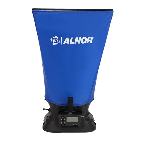
Alnor APM 150 User manual

Electronic
Balometer®with
APM 150 Meter
OWNER’S MANUAL

LIMITATION OF WARRANTY AND LIABILITY
Seller warrants the goods sold hereunder, under normal
use and service as described in the operator's manual, shall
be free from defects in workmanship and material for
twenty-four (24) months, or the length of time specified in
the operator's manual, from the date of shipment to the
customer. This warranty period is inclusive of any
statutory warranty. This limited warranty is subject to the
following exclusions:
a. Hot-wire or hot-film sensors used with research
anemometers, and certain other components when
indicated in specifications, are warranted for 90 days
from the date of shipment.
b. Parts repaired or replaced as a result of repair services
are warranted to be free from defects in workmanship
and material, under normal use, for 90 days from the
date of shipment.
c. Seller does not provide any warranty on finished
goods manufactured by others or on any fuses,
batteries or other consumable materials. Only the
original manufacturer's warranty applies.
d. Unless specifically authorized in a separate writing by
Seller, Seller makes no warranty with respect to, and
shall have no liability in connection with, goods which
are incorporated into other products or equipment, or
which are modified by any person other than Seller.
The foregoing is IN LIEU OF all other warranties and is
subject to the LIMITATIONS stated herein. NO OTHER
EXPRESS OR IMPLIED WARRANTY OF FITNESS
FOR PARTICULAR PURPOSE OR
MERCHANTABILITY IS MADE.
TO THE EXTENT PERMITTED BY LAW, THE
EXCLUSIVE REMEDY OF THE USER OR BUYER,
AND THE LIMIT OF SELLER'S LIABILITY FOR ANY
AND ALL LOSSES, INJURIES, OR DAMAGES
CONCERNING THE GOODS (INCLUDING CLAIMS
BASED ON CONTRACT, NEGLIGENCE, TORT,
STRICT LIABILITY OR OTHERWISE) SHALL BE
THE RETURN OF GOODS TO SELLER AND THE
REFUND OF THE PURCHASE PRICE, OR, AT THE
OPTION OF SELLER, THE REPAIR OR
REPLACEMENT OF THE GOODS. IN NO EVENT
SHALL SELLER BE LIABLE FOR ANY SPECIAL,
CONSEQUENTIAL OR INCIDENTAL DAMAGES.
SELLER SHALL NOT BE RESPONSIBLE FOR
INSTALLATION, DISMANTLING OR
REINSTALLATION COSTS OR CHARGES. No Action,
regardless of form, may be brought against Seller more
than 12 months after a cause of action has accrued. The
goods returned under warranty to Seller's factory shall be
at Buyer's risk of loss, and will be returned, if at all, at
Seller's risk of loss.
Buyer and all users are deemed to have accepted this
LIMITATION OF WARRANTY AND LIABILITY,
which contains the complete and exclusive limited
warranty of Seller. This LIMITATION OF WARRANTY
AND LIABILITY may not be amended, modified or its
terms waived, except by writing signed by an Officer of
Seller.
Service Policy
Knowing that inoperative or defective instruments are as
detrimental to TSI as they are to our customers, our service
policy is designed to give prompt attention to any
problems. If any malfunction is discovered, please contact
your nearest sales office or representative, or call
Customer Service at (800) 424-7427 (USA) and (1) 651-
490-2811 (International).
1
ELECTRONIC BALOMETER
WITH APM 150 METER
SECTION I: ENGLISH 2
SECTION II: SPANISH 23
SECTION III: FRENCH 47


3
TABLE OF CONTENTS
General Description..............................................................................................................2
Safety.....................................................................................................................................2
Getting Started......................................................................................................................3
Installing Batteries.............................................................................................................3
Preparing the Instrument...................................................................................................3
Hood Attachment ........................................................................................................3
Alternate Hood Installation................................................................................................5
Standards..........................................................................................................................6
Flow Resistance................................................................................................................6
Temperature......................................................................................................................7
Atmospheric Pressure.......................................................................................................7
Attaching the Optional Probes (175, 275, 220B) ..............................................................7
Clearing the Memory.........................................................................................................7
The Display............................................................................................................................8
Detailed Operation................................................................................................................8
A. APM 150 Keypad and Menus...................................................................................10
The APM 150 Keypad...............................................................................................10
Primary Key Functions........................................................................................10
Secondary Key Functions ...................................................................................11
Menu Selections........................................................................................................11
Menu Items..........................................................................................................11
B. Using the APM 150...................................................................................................12
Basic Functions.........................................................................................................12
To Change Units .................................................................................................12
To Hold a Reading (For storage or printing) .......................................................12
Measurement Modes ................................................................................................12
Volume Selection ................................................................................................12
Data Storage.............................................................................................................13
Troubleshooting..................................................................................................................14
Maintenance........................................................................................................................15
Appendix A: Traversing a Duct to Determine Average Air Velocity or Volume............15
Where to Take the Measurement....................................................................................15
Traversing a Round Duct................................................................................................16
Traversing a Square Duct...............................................................................................16
Notice of Disclaimer........................................................................................................17
Appendix B: Time Constant Averaging Technique .........................................................17
Appendix C: Serial Communication Using Microsoft®WindowsTM “Terminal” ............18
Appendix D: Correction Factors for ThermoAnemometers to Actual Conditions.......19
Appendix E: Optional Probes Specifications...................................................................20
Service Information ............................................................................................................21

2
2
GENERAL DESCRIPTION
The Alnor Electronic Balometer system with the
APM 150 meter is designed to measure supply or
exhaust air flow from diffusers or grills in HVAC
systems. The assembly consists of a meter, nylon
hood, handles, and a base. The meter has a digital
readout of volume flow and temperature when
used with a Balometer base. The range of
measurement spans from 50 to 2000 CFM (85 to
3400 m3/h or 24 to 945 l/s) and 32ºF to 122ºF (0ºC
to 50ºC). The meter sums and averages air flow up
to 100 points.
Functions are selected through a 7-key pad on the
APM 150. In addition, you can choose from
among many menu-driven items for added
measuring flexibility. Options such as units of
measurement and time-constant settings can also
be selected.
The APM 150 displays measurement results on a
liquid-crystal display (LCD), with additional
display segments for memory locations and units
of measure.
The instrument’s memory can hold 100 readings
of velocity, volume, or temperature. For
convenience, memory can be organized into
sections called “pages.” All data is saved in
battery-backed memory.
Readings can be printed during operation by an
optional printer, or can be saved for subsequent
downloading. The RS232-C serial connection
attaches the APM 150 to a printer or personal
computer.
The adjustable tilt mechanism allows you to
comfortably read the meter from a wide range of
angles.
The APM 150 meter can be disconnected and
removed from the base and used with a variety of
TSI probes.
Three replaceable AA size batteries power the
instrument. You can enable an automatic shut-off
to increase battery life.
SAFETY NOTICE
! When using the instrument to check air flow
in an elevated workplace, make certain that
you can safely raise and hold the instrument
while making measurements. This is
especially important when you are working on
a ladder.
! Avoid catching attachments in moving
machinery.
! Use the instrument only for measurements
using air.
! Avoid any corrosive or other dangerous or
explosive gas mixtures.
Please dispose of used
batteries in a
responsible manner.

3
3
GETTING STARTED
Installing Batteries
The APM 150 uses three (3) AA size non-
rechargeable batteries. The unit is shipped with
batteries not installed. You will find the batteries
in the instrument package.
Figure 1—Front view
To install the batteries:
! Loosen the battery cover screw on the front of
the instrument.
! Slide the cover left and lift it out (Fig. 1).
! Install the batteries over the pull strap, taking
care to observe each battery’s polarity.
! Replace the cover and tighten the screw.
Note: When the batteries become low, the LCD
will show [ ] above the reading. From
that point, you will have about one hour of normal
use left. If [ ] comes on continuously and
replaces the reading, the battery voltage is too low
for accurate measurements and the meter will turn
itself off.
Always keep a replacement set of new batteries
available.
Preparing the Instrument
The meter is shipped with its auto shut-off feature
enabled. This setting will automatically turn the
unit off after a twenty-minute period of keypad
inactivity. To disable this feature, follow the
instructions in the menu selections (see page 11).
Before removing any parts from the carrying case,
the arrangement of the various items should be
noted so that repacking can be done easily. See
Figures 2 and 3.
If your instrument is equipped with more than one
hood, the frame channels needed to support other
sizes are stored under the base of the Electronic
Balometer inside the accessory case. The extra
hoods are stored around the Electronic Balometer
base.
Figure 2—Top view of carry case
Figure 3—Unpacking accessory case
Hood Attachment
Step 1: Remove the tie down straps at the two
locations shown in Figure 2.
Step 2: Holding the 2 ft x 2 ft (600 x 600 mm)
hood frame, gently lift the entire
instrument assembly and set it to the side
of the carrying case.

4
4
Step 3: The accessory case, located underneath
the Electronic Balometer, is now exposed.
Lift the pull tab and pull back to expose
the accessory items. See Figure 3. Remove
the spider assembly, support dowels and
handle from the case. Figure 3 also shows
the packing position of the accessory
frame channel pieces. If installing a
different hood size, remove these pieces at
this time.
Note: The APM 150 Electronic Balometer system
comes from the factory with a 2 ft. x 2 ft. (600 x
600 mm) nylon hood installed on the base. The
following steps will complete the preparation of
the Electronic Balometer for use with this hood. If
a different hood size is required for first time use,
go to the section titled ALTERNATE HOOD
INSTALLATION.
Step 4: Unfold the spider assembly mechanism.
See Figure 4. This mechanism will now be
inserted into the four hood support
brackets located in each corner of the
base. Grasp one of the wire formed legs in
each hand. Insert each of the legs into the
center hole of the hood support brackets.
Grasp the remaining two legs and insert
them into the center holes of the remaining
hood support brackets. If it is later found
that the hood is not held as tautly as
required, the spider assembly can be
moved upward to compensate.
Step 5: Place the four support dowels on the
spider assembly mechanism as shown in
Figure 4. The aluminum tips on the
dowels should be facing up. If a 2 x 4 or
3 x 3 (600 x 1200 or 900 x 900 mm) hood
set is to be used, the set of 8-inch
(200 mm) long dowels must be added to
either end of the long dowels.
Step 6: Raise the hood up until it is taut. Insert a
support dowel into one of the corners of
the frame nearest to you. Take care to
ensure that the support dowel is not
pressing against the hood material. Insert a
second support dowel into the remaining
corner close to you. Lift up the far side of
the hood. Pressing firmly down on the
support dowel, move the dowel into the
third corner. Finally, pressing down on the
last dowel, insert it into the remaining
corner.
Step 7: If desired, install the detachable handle
next, as shown in Figure 4.
Figure 4—Instrument assembly
Make a habit of
checking the tightness of
this handle each time before use. Be sure it does
not loosen while the instrument is being used or
while it is being carried from place to place.
Step 8: Verify that the sensor connector is
attached to the meter. If it is not attached,
line up the key as shown in Figure 5 and
firmly press the connector into the meter.
Tighten the connector by rotating the
knurled ring.
Figure 5—Sensor connector attachment

5
5
Step 9: Verify that the handle hold button
connector is plugged into the sensor
module as shown in Figure 6.
Figure 6—Hold button connector attachment
Step 10: The meter may be tilted for convenient
viewing by loosening the tilt release
knobs located under the meter. Adjust
the meter to the desired angle and
tighten the knobs.
See Figure 7 for various ways to hold the
Electronic Balometer.
Figure 7—Holding Balometer for measurement
To begin using the APM 150 Electronic Balometer
system, proceed to Keypad and Menu selections.
Tip: Before using the Electronic Balometer, allow
the unit to warm up for 15 minutes to achieve best
possible accuracy (Deactivate Auto Shut-off.) The
meter may be turned on before the hood is set up
to minimize waiting time before taking
measurements.
Alternate Hood Installation
Refer to Figures 8 through 11 to determine the
frame channels needed to assemble any of the
standard sized frames. Select the pieces required
for the frame size desired and assemble with the
aid of the appropriate figure. Each channel is
labeled with its number for easy identification.
Several sections (numbers 1, 3, and 4) consist of a
straight channel portion (each a different length)
and a corner piece. This corner piece has an eyelet
and slot arrangement which mates with a similar
eyelet and slot at the end of the straight portion of
the channel pieces (see Figure 12). These pieces
can be slid together and are self locking by means
of a retention spring. The arrangement forms a
rugged frame which is additionally strengthened
when the hood is attached.
Figure 8—1' x 4' Frame (305 x 1220 mm)
Figure 9—2' x 4' Frame (610 x 1220 mm)

6
6
The number 1 and 5 channels also have a wing nut
at the straight end which will mate with an angle
and studs on the ends of numbers 2, 5 and 6 to
form the longer frame sides (see Figure 13).
Figure 10—1' x 5' Frame (305 mm x 1525 mm)
Figure 11—3' x 3' Frame (915 mm x 915 mm)
Figure 12—Frame corner
assembly Figure 13—Frame
side assembly
Each hood is constructed in a trapezoidal shape,
sewn together so that one open end forms a square
attachment to the base, and the other forms a
square or rectangle large enough to fit its matching
frame assembly. Around each end of the hood, an
elastic “shock” cord has been sewn into the hood.
This cord is of a size such that it can be pushed
into the open side of the U-shaped channels of the
frame and around the top of the base.
In general, attach a hood to the frame first, and
then to the base unit. By stretching around the
corners the cord is slightly reduced in diameter
and is easier to press into the channel.
Note: The hood corners should always be aligned
with the corners of the base, near the hood
support brackets. The base has rivets located in
the corners which can be used as a guide for
aligning the hood corners.
Standards
All Balometers or hoods are calibrated to some
standard. Different manufacturers or calibration
facilities may use standards or methods that are
different from those used at TSI Incorporated. TSI
uses laminar flow elements as the standard to
calibrate Balometers. These are devices that are
made up of a very fine honeycomb mesh. The
pressure drop across a laminar flow element is
approximately linear with the flow going through
the element. Alnor Balometers are calibrated using
a standard two by two foot square diffuser. Other
manufacturers may use orifice plates or nozzles
and may not use a diffuser.
When using proportional balancing techniques,
these differences will not be important. However,
when comparing Balometers against other hoods,
or when comparing Balometers calibrated at TSI
with other calibration facilities, these differences
may be important. It is not unusual to see air flow
calibration differences on the order of 5% because
of different standards.
Flow Resistance
All capture hoods cause flow resistance on the air
handling system. Just as different diffuser styles
have their own characteristic flow resistance, so do
capture hoods. This added resistance reduces the
true amount of air exiting the diffuser. In the
majority of cases, this error is less than or equal
to the accuracy of the instrument. Proportional
balancing techniques will also assist in making
these effects negligible.
To determine if the flow resistance effects are
important, perform duct traverses to determine the
volume rate exiting a diffuser both with and
without the capture hood in place. The difference
between the volume rate with and without the
capture hood in place is the flow resistance effect
for that diffuser.

7
7
To determine a flow resistance correction factor
for use with similar diffusers and duct
configurations, use the volume rates as determined
from the duct traverses both with and without the
hood as follows.
Vhood = Flow rate with the hood in place
Vno hood = Flow rate without the hood in place
CF = Vno hood /Vhood
Vmeasured = Volume rate as displayed by the
capture hood
Vcorrected = Volume rate corrected for the flow
resistance of the capture hood
Vcorrected = CF x Vmeasured
Temperature
The temperature readout on the APM 150 meter
indicates general trends in the air temperature
coming from a diffuser. The Electronic Balometer
has a temperature sensor located inside an
aluminum housing behind the meter. Because of
the mass of the housing, the Electronic Balometer
will show a lag in temperature reading from actual
if the air temperature is changing. The time
response of the temperature channel depends on
the amount of flow passing through the Balometer.
For flows under 200 CFM (100 l/s, 340 m3/h), the
temperature time response is in the order of
minutes. For fast measurements of air flow
temperature, the Alnor 175 or 275 probe is
recommended. To compare the temperature
reading of the Electronic Balometer to a standard,
the air flow temperature must remain constant to
within 0.25 degrees C.
Atmospheric Pressure
Above 500 CFM (250 l/s, 850m3/h), large changes
in atmospheric pressure can affect readings from
the Balometer. The correct value is inversely
proportional to the atmospheric pressure. A
change in atmospheric pressure of –3% will
require the display to be multiplied by +3%. See
Appendix E for additional information.
Note: When using the Balometer, make sure that a
complete seal is made around the diffuser. Any
leaks will cause measurable errors.
Attaching the Optional Probes (175,
275 and 220B)
Refer to page 9 on removing the meter from the
base.
To attach the probe for measuring air velocity:
! Make sure the meter is off before attaching or
detaching a probe.
! Remove the protective cap from the probe and
save for restoring the probe later.
! Attach the 12-pin connector on the probe to
the probe port on the meter.
! Turn the connector clockwise to tighten.
Depending on the connected sensing device, you
will have a choice of available units.
Sensing Device Available Units
Balometer Hood l/s, m3/h, cfm, °F, °C
ThermoAnemometer
Probe
l/s, m3/h, cfm, kmh,
m/s, mph, fps, fpm, °F,
°C
220B Relative
Humidity Probe
RH, °F, °C
Clearing the Memory
If this is the first time you are using the APM 150
meter, clear the memory before using the
instrument.
Clearing the memory is done with the following
steps:
• Push CLR until [ ] appears.
• Push ↑ until [ ] appears.
• Push ↵ to clear memory.
The meter starts in RUN mode. It will display
measurement values associated with the unit last
used. If the value is OVERRANGE the display
will show [ ]; similarily if the instrument is
measuring an UNDERRANGE value the display
will show [ ].

8
8
THE DISPLAY
The APM 150 incorporates a custom liquid crystal
display (LCD) to show measured values, units of
measurement, page and line numbers of last data
entered, and an indicator showing if the correction
factor is equal to 1. As a result, measurements
exceeding 9,999 of a given unit of measure will be
displayed in a scientific notation format of XXEY.
The actual reading will be rounded to the nearest
thousand, XX. The Y indicates the number of
zeros after XX. For example, 12,751 is displayed
as [ ].
The APM 150 is measuring and averaging the
actual value of the reading, not the rounded
scientific notation value. No accuracy loss will be
encountered. When printing the data on the 8521
MicroPrinter or downloading the data to a host
PC, the scientific notation reading will be seen.
DETAILED OPERATION
With the meter turned on, assemble the hood (see
page 4). The display will show:
• All segments of the display
• The latest software revision
• The type of probe attached (175, 275, 220B)
• Busy message
• An air flow measurement
Note: If the meter displays [ ] turn unit off
and check the probe connection. If this is the first
time you used the meter, clear the memory (see
page 7).
Check to see if the meter’s parameters are set for
your application. The meter always starts
measuring in the SUPPLY mode. To select
exhaust, press the supply/exhaust key ( ). If the
meter is in the exhaust mode, the annunciation
below Ex will be on. If a correction factor is
needed, press the MENU key until [ ] is
displayed. Press ↵, then press ↑ or ↓ until the right
value appears, then press ↵. [ ] will be
displayed. Press ON/OFF to return to the RUN
mode.
To change the units of measure, press the UNIT
key until [ ] appears. Press the ↑ or ↓ button
until the annunciation is pointing to the correct
unit. Press ↵.
To take a measurement, raise the hood assembly to
the diffuser, making certain the hood frame fits
around the entire diffuser and is held tightly
against the ceiling or wall (see page 5). Let the
display settle to a steady reading. Press the HOLD
key (you may use the red button on the right
handle or the HOLD/AVE button on the meter).
The display will flash the measured value. If this
reading is not satisfactory, press the ON/OFF key
to return to the RUN mode without storing the
value. If the reading is satisfactory, press the
HOLD key again to store the value. Repeat this
procedure as many times as needed.
If the data is complete and another set of
measurements is needed, create a new page. To
achieve this, press the MENU key until [ ]
is displayed. Notice the smaller indicator to the
right. This displays the current working page.
Press ↵, the display will automatically increase the
page number. To return to the RUN mode press
ON/OFF.
To examine the stored data, press the MEM key.
The display will show the current working page.
To scroll to any of the stored pages use the ↑ or
↓ key until the desired page number appears, then
press ↵. The display will now show the stored line
number, the value stored and its units. To continue
reviewing the data, press the ↑ key.

9
9
When all the stored data is displayed, the last
display will show the average or sum of the
current page. Pressing up again will return the
meter to the “memory page number” display. Press
↑ or ↓ to view another page or ON/OFF to return
to the RUN mode.
If a printer is attached when pressing the HOLD
key for the second time, the data will be stored in
memory and printed. To get a hard copy of the
stored data from a printer or to download to a
computer, press the MENU key until [ ]
appears, press ↵. The printed information will
look like this:
MEMORY # (# is the page number)
(line number) (the measured value) (its units)
“ “ “
“Temperature”
minimum value maximum value
average value number of stored entries
“Flow”
minimum value maximum value
average (or sum) value number of stored entries
Date
_____________________
Name
–––––––––––––––––––––
This will repeat for all stored pages. After all data
is printed, press the ON/OFF key to return to the
RUN mode.
To escape from the print routine, press and hold
the ON/OFF key until the print stops. [ ]
will be displayed. Press ON/OFF again to return
to the RUN mode.
To examine the average value of the stored data
(current page only) press and hold the HOLD/
AVE key for approximately 3 seconds. The word
AVE will appear, then the calculated value and its
units of measurement. To return to the RUN mode
press the ON/OFF key.
Note: To remove the meter, squeeze the meter
release latch and lift out the meter as shown in
Figure 14. Replace the meter by squeezing the
release latch, inserting the left side of the meter
under the “L” bracket then laying the meter flat
against the sensor housing before releasing the
latch. Make sure that the meter is secure before
moving the Balometer.
Figure 14—Removing the meter from the base
(2) Squeeze
Release Latch
(3) Lift Meter
From Base
(1) Disconnect
Plug Connector
From Meter

10
10
A. APM 150 Keypad and Menus
The APM 150 Keypad
Each key has two different functions. The primary
function is shown above the diagonal line on the
key’s surface. The secondary function is shown
below the diagonal line. A more detailed
description of each function follows.
In the RUN mode, if a key is held for less than
three seconds, the primary function is activated.
When a key is held for more than three seconds,
the secondary function is activated. The
exceptions to this are the ↑ and ↓ keys. Because
they are used to move between menu options,
these keys do not function in RUN mode.
The cycle time of the
APM 150 software
may cause the meter to react slowly to a key push.
The reaction time of a key push will vary with
different functions (1–3 seconds). Do not push a
key twice because of a slow response time. Doing
so may result in accidental activation of a
secondary function or duplication of a desired
function.
Primary Key Functions:
ON/OFF
This key is used to turn the
instrument on or off when in the
RUN mode. If the instrument is in
any other mode, pressing this key
will exit that function and go back
to the RUN mode without making
any changes.
VOL
(Used only if a 175 or 275 probe is
attached.) The VOL key prepares
the APM 150 for air volume
measurements. After pressing this
key, you must indicate whether
you’re measuring by area, or
whether you’re measuring a round
or rectangular duct. Choose one of
these options by pressing the ↑or
↓key, followed by the ↵key to
make a selection. After you make
your selection, use the ↑or ↓ key
to enter the dimensions, then the
↵key to enter the units.
MENU
MENU allows you to select one of
several options. Use the ↑or
↓keys to move through the
choices. To choose a selection,
push ↵, or return to RUN mode by
pushing ON/OFF. The MENU
selections are as follows:
[] Changes memory page
[] Prints all stored data
[] Correction Factor
[] Enables or disables auto
shut-off
[] Scans meter voltages
[] This is only used by the
factory
[] Enables or disables the
serial port
[] Time constant selection
(See also “Menu Selections,” next
page.)
HOLD
Pressing this key freezes data in
RUN mode for input to memory or
output to a printer. The display
flashes. Pushing HOLD again
stores and prints your data.
Pressing ON/OFF returns you to
RUN mode without storing or
printing.

11
11
UNIT
The UNIT key allows you to select
a unit of measurement. The ↑and
↓ keys move through the choices.
Use the ↵ key to accept a choice,
or press ON/ OFF to return to
RUN mode without making
changes.
MEM
The MEMORY key is used to
review stored data. When it is
pressed, the display will show the
current page number. The ↑and
↓keys will move you to any page
you wish to review. To examine
data, press the ↵ key.
If memory is empty, the unit
automatically jumps back to RUN
mode. Otherwise, you can return
there by pressing the ON/OFF
key.
(See also PAGES in “Data
Storage.”)
Push this key to select SUPPLY
or EXHAUST air measurement
modes. The meter’s default is
SUPPLY. A display annunciator
▲will indicate EXHAUST (EX)
when it is in that mode.
Secondary Key Functions:
↑and ↓
These keys allow you to move or
scroll through menu selections in
forward (↑) or reverse (↓) order.
AVE
If held for three (3) seconds, the
AVE key lets you view the
average of the current page of
measurements which has been
stored. Pushing ON/OFF returns
you to RUN mode.
↵
This key accepts all selected
choices such as values and menu
items. After each entry, [ ]
appears on the display as the APM
150 stores new information.
Menu Selections
Pressing the MENU key activates the main menu.
Use the ↑and ↓keys to scroll through the
available selections. Once you find your desired
selection, choose it by pressing ↵. Pressing
ON/OFF exits the menu, returning you to RUN
mode.
Menu items (to select any of the following
press ↵):
Measurements stored in the
instrument’s memory are organized
into pages. This key changes the
page onto which you are saving your
measurements. If there is no stored
data on the current page, the page
number will not increase. A total of
100 sets, or lines, of data can be
stored. You may have 100 pages of
one line each, one page of 100 lines
each, or any combination of pages
and lines not exceeding 100
readings.
This copies all stored data to a
connected printer or computer. You
can abort the printout at any time by
pressing and holding the ON/OFF
key.
The Correction Factor is an all-
purpose multiplying factor which is
applied to all measurements. cF is
set to 1.000 unless it is changed in
the menu. An annunciator (▼) tells
you when “cF=1.” cF is usually used
when air density conditions deviate
from standard. See Appendix D.
Select values with the ↑or ↓ key,
then press ↵ to accept them or
ON/OFF to reject them.
This automatic shut-off option can
be enabled or disabled by pushing
↑ or ↓ to select [ ] or [ ],
then pushing the ↵ key to enter your
selection. When enabled, the
automatic shut-off will power-down
the APM 150 after 20 minutes of
keyboard inactivity.
This diagnostic tool allows you to
view important analog voltages
within the instrument. Pushing ↑ or
↓ views the eight different channels,
which include the following:

12
12
— O V dc.
— 4.965 to 5.025 V dc.
— battery voltage (3.5 V
fresh batteries)
Factory use only.
This option allows you to enable or
disable the serial port. In the normal
RUN mode, the port must be
disabled (increases battery life).
To enable port
• At menu selection [ ], press
↵.
• Press ↑ or the ↓ until appears.
• Press ↵.
To disable port
• At menu selection [ ], press
↵.
• Press ↑ or the ↓ until
appears.
• Press ↵.
tc allows you to select from five
different speeds of display response.
• A setting of 1 is a quick response.
• A setting of 5 is a slow response.
B. Using the APM150
Basic Functions
To Change Units:
! Push the UNIT key until [ ] appears.
! Use the ↑and ↓keys to view new measurement
units.
! The display annunciator ▲will move to the
selected unit (see Figure 3).
! Push ↵ to select a new measurement unit.
For example: To change the units of measurement
from cubic feet per minute (cfm) to cubic meters
per hour (m3/h) while using a thermo-anemometer
probe:
Figure 15—Display with annunciator and units of
measure
! Push the UNIT key until [ ] appears.
! Push ↑until the display annunciator ▲moves
to m3/h, selecting cubic meters per hour.
! Push ↵ to select the measurement unit.
Note: Not all units are achievable with the
attached hood.
To Hold a Reading (For storage or printing):
! Push the HOLD key briefly until the measured
value flashes.
! Push HOLD again to STORE this reading to
memory, or push ON/OFF to reject it and return
to RUN mode.
! If the meter is attached to the base, you may also
push the red button on the right handle for your
hold functions.
Measurement Modes
You can set the APM 150 for temperature or
volume measurement by pressing the UNIT key.
Volume Selection
(when a 175 or 275 probe is attached):
Air volume measurement is achieved by
multiplying a velocity reading by an area.
• When you press the VOL key, the [ ]
menu appears on the display and provides a way
to choose whether you are measuring by area (in
square units) or by a round or rectangular cross-
section.
• Make your selection by scrolling using the ↑ and
↓ keys, then pressing the ↵ key to accept your
choice.

13
13
• If you choose to use a cross-section, you must
then indicate dimensions as follows.
Area:
(Also to review the Area or selected horn)
When selected by pressing the ↵ key, the
following will appear:
• The current units, either ft2[] or m2[]
• The current horn (if previously used)
• The numeric value of the calculated area.
Note: If you only wanted to review, press the
ON/OFF key.
• If you press the ↵ key, the ↑ or ↓ key (value
change), then the ↵ key, you change the method
of measurement to [ ].
Rectangular:
• After [ ] is selected, the display will show
starting X dimension values [ ] in inches or
[] meters. Accepting the X value affects
choice of a volume dimension (e.g. cfm).
• Change these values using ↑ or ↓. Press the
↵ key to accept.
• The next display shows desired Y dimension
values of [ ] in inches or [ ] meters.
• Change these values using ↑ or ↓. Press the
↵ key to accept.
Round:
• After [ ] is selected, the display will show
starting point diameter values [ ] in inches
or [ ] meters.
• Change the value to the necessary diameter using
↑ or ↓. Press the ↵ key to accept.
Horn:
• When selected, use the ↑ or ↓ keys to scroll
through the following options:
—AM100 [ ]
—AM300 [ ]
—AM600 [ ]
—AM1200 [ ]
• Press ↵ to select one of these choices.
• To review, see Area.
Data Storage
All measurements stored in the instrument’s
memory are recorded on pages. A page is created
whenever:
• the unit of measurement changes,
• or page is selected from the MENU.
For example, if you are measuring feet per second
and decide to take measurements in miles per
hour, a new page will be created.
The APM 150 memory has a total capacity of 100
sets of data. This means you can have one page of
100 lines, or one hundred pages of one line, or any
combination of pages and lines totaling 100
readings.
Each time the HOLD key is pressed for the
“second” time, the instrument will store
measurements and the correction factor. Readings
are stored in battery-backed memory so that
powering off or changing batteries does not erase
readings. These stored readings will remain in
memory until they are cleared or if the instrument
is damaged or malfunctions.
A copy of this data can be obtained if a printer or
computer is attached to the instrument.
If a printer is connected:
• Press the MENU key, then the ↑ or ↓ key until
[] appears.
• Press ↵ to print the data.
• To escape from the print routine, press and hold
the ON/OFF key until [ ] appears, then
press the ON/OFF key to return to the RUN
mode.
To erase stored data:
• Press the CLR key until [ ] appears.
• Push the ↑ or ↓ key until [ ] appears.
• Press ↵ to clear the memory.
Note: Keep in mind that you cannot erase
individual pages. Clearing data erases
every page in the instrument’s memory.

14
14
TROUBLESHOOTING
Symptom Probable Cause/Corrective Action
No Display Instrument is not on. Press ON/OFF.
Dead batteries. Replace batteries.
Batteries incorrectly installed. Check polarity and
correct if required.
LO BAT indication on Battery voltage is low. Replace batteries.
Random pattern on display Battery voltage is too low. Replace batteries.
Display does not change or flashes HOLD/AVE button was depressed. Press hold again
to release.
Very stable input. Meter could be in another mode
besides RUN.
Display shows [ ] Input condition below minimum allowed. See
SPECIFICATION section of manual for limits.
Display shows [ ] Input condition above maximum allowed. See
SPECIFICATION section of manual for limits.
Display shows [ ] Probe or sensor not connected or loose. Check
connection to meter. Tighten connector if required.
Probe or sensor damaged. Call TSI.
HOLD/AVE button on handle does not work Connector between handle and meter is not plugged
in. Connect hold cable to sensor module.
Measurement is erratic Input is unstable. Interpret value from high and low
display limits or increase time constant setting.
Erroneous readings Wrong measurement units. Verify correct units.
Hood frame not sealing properly around diffuser or
grill. Press hood evenly against diffuser.
Hood torn. Replace or repair hood.
Supply/Exhaust Exhaust mode was incorrectly chosen when
measuring supply flow or vice versa. Check mode.
Display shows “▲” sign for exhaust mode. Absence
of “▲” indicates supply mode. Use key to select
desired mode.
Note: meter always starts up in supply mode.
Connection between manifold and sensor/meter is
broken. Call TSI.
Manifold is damaged. Call TSI.
Manifold holes are plugged. See Maintenance section
of manual.
Condensation inside sensor module. Allow unit to
warm up to room temperature.
Will not transmit data to computer Make sure the terminal is set properly. The serial port
must be enabled.

15
15
MAINTENANCE
Nylon Hoods
The hoods may be hand washed periodically using
cool water and mild detergent. When washing, do
not let the material come in contact with sharp
corners or other objects which may tear the hood.
Manifold
The manifold should be checked before using to
be certain that the sensing holes have not become
clogged with dirt or dust particles. Inspect for
leaks which may be caused by a poor connection
to the sensor housing through the long pieces of
flexible tubing. Also check to make sure that the
O-rings used to seal the tubes to the center hub are
in place.
The manifold may be cleaned using mild detergent
and warm water. Do not immerse the manifold in
water. It is recommended that cleaning be done
with the manifold in place, and with care.
APPENDIX A:
TRAVERSING A DUCT TO DETERMINE AVERAGE AIR VELOCITY OR
VOLUME (ONLY WITH A 175 OR 275 PROBE ATTACHED)
The following techniques can be used to measure
air flow inside ducts using a velocity probe.
Where to Take the Measurement
In order to make air velocity measurements in a
duct, it is best to measure at least 7.5 duct
diameters downstream and at least 3 duct
diameters from any turns or flow obstructions. It is
possible to do a traverse as little as 2 duct
diameters downstream or 1 duct diameter upstream
from obstructions, but measurement accuracy will
be impaired. When measuring rectangular ducts,
use the following formula to find the equivalent
diameter of the duct when calculating how far 7.5
diameters downstream or 3 diameters upstream is.
Equivalent Diameter = 4HV/Pi
Where: H = horizontal duct dimension
V = vertical duct dimension
Pi = 3.14
It is also possible to take a single reading to
measure air velocity or air volume flow in a duct,
measuring in the center of the duct and
multiplying the reading by 0.9 to correct for the
higher velocity at the duct’s center. If conditions
are very good, accuracy of ±5 or ±10 percent can
be obtained this way. This method is not reliable,
however, and should only be used where small
duct size or other conditions do not permit a full
traverse.
Traversing a Round Duct
Using the log-Tchebycheff method, the duct is
divided into concentric circles, each containing
equal area. An equal number of readings is taken
from each circular area, thus obtaining the best
average. Commonly, three concentric circles (six
measuring points per diameter) are used for ducts
with diameters of 10 inches or smaller. Four or
five concentric circles (eight or ten measuring
points per diameter) are used for ducts with
diameters of 10 inches or more.

16
16
Figure 16—Location of measuring points when
traversing a round duct using the log-Tchebycheff
method.
*The APM 150 Multi-Purpose Meter is able to calculate
averages automatically, thus eliminating the need for
additional calculations. Refer to “AVE” on page 11 of this
manual.
Number of measuring
points per diameter Position relative to
inner wall
60.32, 0.135, 0.321, 0.679,
0.865, 0.968
8 0.021, 0.117, 0.184,
0.345, 0.655, 0.816,
0.883, 0.981
10 0.019, 0.077, 0.153,
0.217, 0.361, 0.639,
0.783, 0.847, 0.923, 0.981
The preferred method is to drill three holes in the
duct at 60° angles from one another as shown in
Figure 16. Three traverses are taken across the
duct, and the velocities obtained are averaged at
each measuring point. The average velocity is
multiplied by the duct area to get the flow rate. (A
different method uses two holes at 90° angles from
one another, decreasing the number of traverses
with the probe by one.)
Before taking the measurement, multiply the
numbers in the table by the duct diameter to get
the insertion depth for the probe. (Do not forget to
use the inside dimension of the duct if it is lined
with insulation.)
Traversing a Square Duct
Using the log-Tchebycheff method, the duct is
divided into rectangular areas, which are further
adjusted in size to account for the effect of the
duct wall on air flow. A minimum of 25 points
must be measured in order to get a good average.
The number of data points to be taken along each
side of the duct depends on how wide the duct is.
For duct sides shorter than 30 inches, five traversal
points must be taken. For duct sides of 30 through
36 inches, six points must be taken. For duct sides
longer than 36 inches, seven points must be taken.
Multiply the numbers in the table by the duct
dimension to get the insertion depth for the probe.
Figure 17—Location of measuring points for
traversing a rectangular duct using the log-
Tchebycheff method.
Number of points or
traverse lines per side Position relative to
inner wall
50.074, 0.288, 0.500,
0.712, 0.926
6 0.061, 0.235, 0.437,
0.563, 0.765, 0.939
7 0.053, 0.203, 0.366,
0.500, 0.634, 0.797,
0.947
Table of contents
Languages:
Other Alnor Measuring Instrument manuals

Alnor
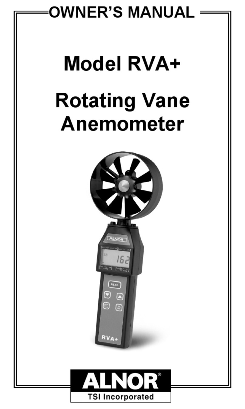
Alnor RVA+ User manual

Alnor
Alnor AXD 530 User manual

Alnor
Alnor 275 User manual

Alnor
Alnor Balometer ABT701 User manual

Alnor
Alnor EBT730 User manual

Alnor
Alnor 9850 User manual

Alnor
Alnor 9870 User manual

Alnor
Alnor AirGard 405 User manual

Alnor
Alnor Airflow Proood PH731 User manual

Alnor
Alnor Balometer 6461 User manual
Popular Measuring Instrument manuals by other brands

Videotek
Videotek TVM9100PKG Installation and operation handbook

Granite River Labs
Granite River Labs GRL-USB-PD-A1 user manual

SMC Networks
SMC Networks PFG20 Operation manual

Endress+Hauser
Endress+Hauser Prosonic M FMU40 technical information

Svantek
Svantek SV 200 user manual

sauermann
sauermann CO2ST-S quick start guide