Seintek S2800 User manual

PROGRAMMABLE
AUTOMOTIVE
SCOPE METER
User’s Manual
S2800_E200611_R01

Programmable
Automotive Scope

i
Contents
1. Easy Manual................................................................................1-1
1.1. Turning on and off................................................................................1-1
1.2. Division, Trigger and Function key.......................................................1-2
1.3. Input Terminals ....................................................................................1-2
1.4. Command, Arrow, Backlight and Help key...........................................1-2
1.5. Primary Menu Map ..............................................................................1-3
1.6. Positioning the waveform on the screen..............................................1-3
1.7. Division key map..................................................................................1-4
1.8. Changing Vertical (A/div or B/div) division...........................................1-4
1.9. Changing Horizontal division ...............................................................1-5
1.10. Trigger key map................................................................................... 1-5
1.11. Trigger level control ............................................................................. 1-6
1.12. Function key map ................................................................................ 1-6
1.13. Sensor tests......................................................................................... 1-7
1.14. Actuator tests....................................................................................... 1-7
1.15. Ignition & Electrical.............................................................................. 1-8
2. Test Examples.............................................................................2-9
2.1. Battery Voltage test.............................................................................. 2-9
2.2. O2 Sensor (Oxygen Sensor) ..............................................................2-11
3. Introduction.................................................................................3-1
3.1. Main Features......................................................................................3-1
3.2. Unpacking the Test Tool Kit.................................................................. 3-1
3.3. Specification ........................................................................................3-2
3.3.1. General Specifications.......................................................................3-2
3.3.2. Technical Specification.......................................................................3-3
4. Product Description....................................................................4-1
4.1. LCD Area.............................................................................................4-2
4.2. Keys Area ............................................................................................ 4-3
4.3. Terminal Area.......................................................................................4-8
5. Using the METER........................................................................5-1
5.1. Safely Using the Test Tool....................................................................5-1
5.1.1. Attention.............................................................................................5-1
5.1.2. Safety Precautions.............................................................................5-1
5.1.3. Powering the METER ........................................................................5-1
5.1.4. Changing Backlight............................................................................5-1
5.1.5. Making Selections in a Menu.............................................................5-2
5.1.6. Displaying only CHA..........................................................................5-2
5.1.7. Freezing the screen...........................................................................5-3
5.1.8. Changing the Graphic Representation...............................................5-4

ii
5.1.9. Acquiring the Waveform.....................................................................5-4
6. Triggering on a Waveform..........................................................6-1
6.1. Setting Trigger level (on NORmal trigger mode).................................. 6-1
6.2. Making a single acquisition.................................................................. 6-1
6.3. Setting Trigger mode (Tmode)............................................................. 6-2
6.4. Setting AUTO Trigger Level.................................................................6-2
6.5. Setting Normal Trigger mode............................................................... 6-3
6.6. Setting Trigger Slope........................................................................... 6-3
7. Storing and Recalling Screens..................................................7-1
7.1. Storing Screen..................................................................................... 7-1
7.2. Recalling Screen..................................................................................7-2
8. Remote Interface Operations.....................................................8-1
8.1. USB HID Device Installation................................................................8-1
8.1.1. System Requirements........................................................................8-1
8.1.2. Operating System..............................................................................8-1
8.2. Verifying the computer's USB port....................................................... 8-1
8.2.1. Installing the HID Device....................................................................8-1
8.3. To install Windows Application Software.............................................. 8-3
8.4. Running the Application Software........................................................8-4
8.4.1. Oscilloscope Mode.............................................................................8-4
9. Maintaining the test tool.............................................................9-1
9.1. About this Chapter...............................................................................9-1
9.2. Static Safe Handling ............................................................................9-1
9.3. Cleaning the Meter .............................................................................. 9-1
9.4. Storing the Meter .................................................................................9-1
9.5. Calibration ........................................................................................... 9-1
9.6. Replacing and Disposing of the Li-ION Battery ...................................9-2
10. Automotive test setup..............................................................10-1
10.1. SENSOR function test ....................................................................... 10-1
10.1.1. ABS sensor......................................................................................10-2
10.1.2. O2 Sensor........................................................................................10-2
10.1.3. ECT Sensor .....................................................................................10-3
10.1.4. Fuel Temp........................................................................................10-3
10.1.5. IAT Sensor.......................................................................................10-4
10.1.6. Knock Sensor ..................................................................................10-4
10.1.7. TP Sensor........................................................................................10-5
10.1.8. CKP MAG ........................................................................................10-5
10.1.9. CKP LoRes......................................................................................10-6
10.1.10. CKP HiRes.......................................................................................10-6
10.1.11. CMP MAG........................................................................................10-7
10.1.12. CMP LoRes......................................................................................10-7
10.1.13. CMP HiRes......................................................................................10-8
10.1.14. VSS MAG ........................................................................................10-8
10.1.15. VSS Digital.......................................................................................10-9

iii
10.1.16. MAPAnalog.....................................................................................10-9
10.1.17. MAP Digital....................................................................................10-10
10.1.18. MAF Analog ...................................................................................10-10
10.1.19. MAF HF Digital...............................................................................10-11
10.1.20. MAF LF Digital...............................................................................10-11
10.1.21. EGR PFE.......................................................................................10-12
10.1.22. EGR DPFE ....................................................................................10-12
10.2. ACTUATOR Function Test............................................................... 10-13
10.2.1. Injector C/LIM ................................................................................10-14
10.2.2. Injector N/LMT ...............................................................................10-14
10.2.3. Injector Positive Negative Positive.................................................10-15
10.2.4. Mixture Solenoid............................................................................10-15
10.2.5. EGR Control Sol ............................................................................10-16
10.2.6. ISC Step Motor ..............................................................................10-16
10.2.7. ISC Motor.......................................................................................10-17
10.2.8. ISC SOL.........................................................................................10-17
10.2.9. Trans Sol........................................................................................10-18
10.2.10. Turbo Boost Sol.............................................................................10-18
10.2.11. Glow Plug Amp ..............................................................................10-19
10.3. IGNITION & ELECTRICAL Function Test ........................................ 10-20
10.3.1. PIP.................................................................................................10-21
10.3.2. SPOUT ..........................................................................................10-21
10.3.3. DI Primary......................................................................................10-22
10.3.4. DI Secondary.................................................................................10-22
10.3.5. El Primary ......................................................................................10-23
10.3.6. El Secondary .................................................................................10-23
10.3.7. Power Circuit .................................................................................10-24
10.3.8. VREF Circuit..................................................................................10-24
10.3.9. Ground Circuit................................................................................10-25
10.3.10. Alt Output.......................................................................................10-25
10.3.11. Alternator Field VR.........................................................................10-26
10.3.12. Alternator Diode.............................................................................10-26
10.4. Automotive test setup table.............................................................. 10-27
11. Appendices................................................................................11-1
11.1. Troubleshooting guide ........................................................................11-1

1-1
1. Easy Manual
?
I / O
600V
MAX
600V
MAX 600V
MAX
FUNC
DIV
F1 F2 F3 F4
TRIG
Front View
1.1. Turning on and off
?
I / O
600V
MAX
600V
MAX 600V
MAX
FUNC
DIV
F1 F2 F3 F4
TRIG
1
Pressing this button for①1 to 2 seconds will
turn the unit on.
Pressing this button again will turn the power
off.
1-2
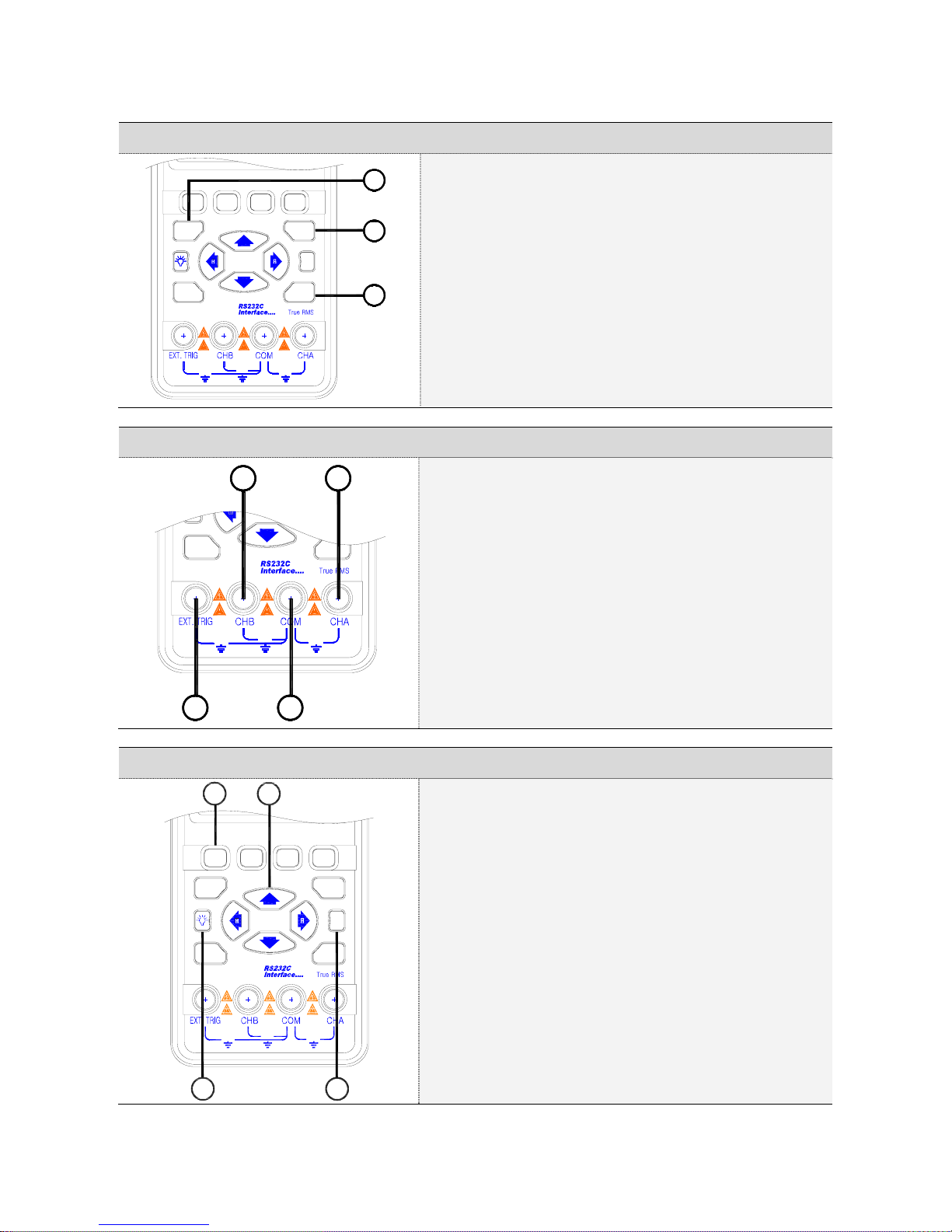
1.2. Division, Trigger and Function key
?
I / O
600V
MAX
600V
MAX 600V
MAX
FUNC
DIV
F1 F2 F3 F4
TRIG
1
2
3
①Division key:
Adjusts vertical division or Horizontal division.
②Trigger key:
Adjusts Trigger level.
Selects Single shot mode.
Selects trigger setup.
③Function key:
Selects Scope Setup.
SelectsAutomotive scope setup.
Selects general setup
1.3. Input Terminals
I / O
600V
MAX
600V
MAX 600V
MAX
FUNC
2 1
34
①Channel A:
You can always use the red channel A for all single
input measurements possible with the meter.
②Channel B:
For measurements on two different signals you can
use the channel B together with the Channel A.
③Common:
You can use the black common as single ground for
low frequency measurements and forACV, DCV,
Ohm, Continuity and RPM measurements
④External trigger:
The EXT.TRIG input accepts external trigger signals.
1.4. Command, Arrow, Backlight and Help key
?
I / O
600V
MAX
600V
MAX 600V
MAX
FUNC
DIV
F1 F2 F3 F4
TRIG
4
2
1
3
①Command keys:
These four keys are command buttons.
They are labeled F1-F4. These keys will have various
functions.
②Four arrow keys:
These keys serve as the primary means of navigating
the instrument’s menus and operating displays.
③Display back light:
Press this button to turn on the backlight. To turn the
back light off, press this button again.
④Help key:
General information for the test tool is available.

1-3
1.6. Positioning the waveform on the screen
MAX
600V MAX
600V
MAX
600V
DIV
I / O
?
FUNC
F1 F2
TRIG
F3 F4
1
2
3
4
Pressing①moves the waveform up.
Pressing②moves the waveform
down.
Pressing③moves the waveform left.
Pressing④moves the waveform right.
1.5. Primary Menu Map
Default Menu
Division Menu
Trigger Menu
Function Menu
1-4
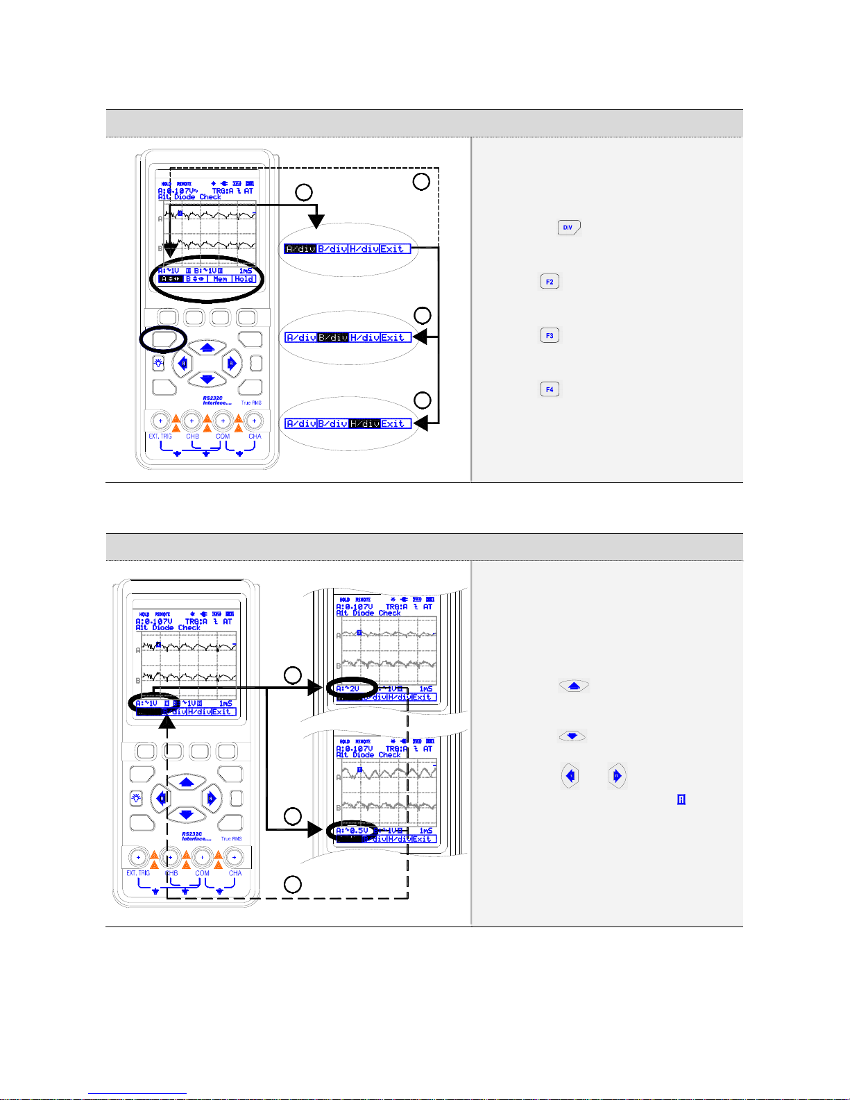
1.7. Division key map
1
2
3
4
MAX
600V MAX
600V
MAX
600V
DIV
I / O
?
FUNC
F1 F2
TRIG
F3 F4
Pressing①calls up the default
division menu.
Press②to control the Channel B
Vertical Division.
Press③to change the Horizontal
Division.
Press④to exit.
1.8. Changing Vertical (A/div or B/div) division
1
2
3
F4
TRIG
FUNC
MAX
600V 600V
MAX 600V
MAX
F2
I / O
F1
DIV
F3
?
Pressing①button increases CHA
vertical division (A/div).
Pressing②button decreases CHA
vertical division (A/div).
Pressing③or key will change
Div from MANUAL to AUTO( ).

1-5
1.9. Changing Horizontal division
1
2
3
600V
MAX
F2
I / O
F1
DIV
F3
?
F4
TRIG
FUNC
MAX
600V 600V
MAX
Pressing①button increases
Horizontal division (H/div).
Pressin②g button decreases
Horizontal division (H/div).
Pressing③or key will change
Div from MANUAL to AUTO( ).
1.10.Trigger key map
MAX
600V MAX
600V
MAX
600V
DIV
I / O
?
FUNC
F1 F2
TRIG
F3 F4
1
4
2
3
Press①key to display the
TRIGGER default menu.
Press②key for Single shot
mode.
Press③key for TRIGGER
SETUP.
Press④to exit.
1-6
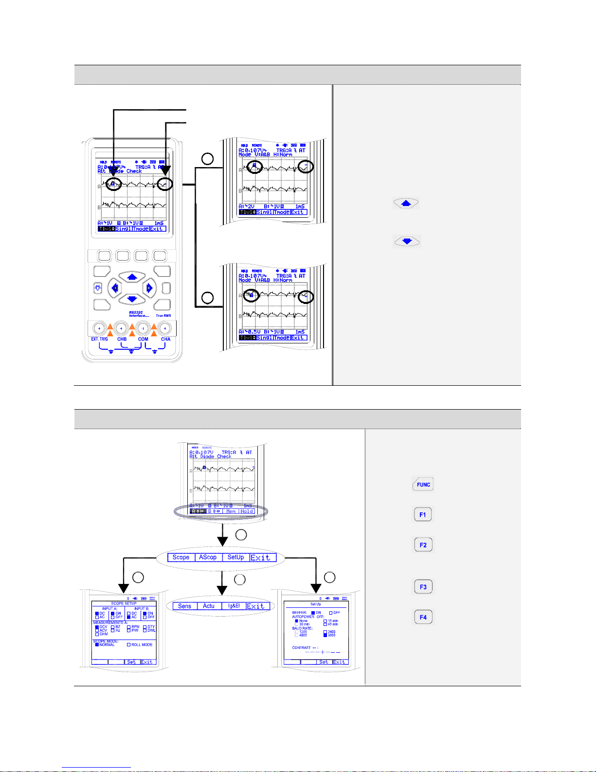
1.11.Trigger level control
F4
TRIG
FUNC
MAX
600V 600V
MAX 600V
MAX
F2
I / O
F1
DIV
F3
?
Trigger point indicator
Trigger level indicator
1
2
Pressing①button increases the
Trigger level.
Pressing②button decreases
the Trigger level.
1.12.Function key map
1
234
Press①key to display the
FUNCtion default menu.
Press②key for SCOPE
SETUP.
Press③key for
AUTOMOTIVE SCOPE
SETUP.
Press④for general
SETUP.
Press⑤to exit.
1-7
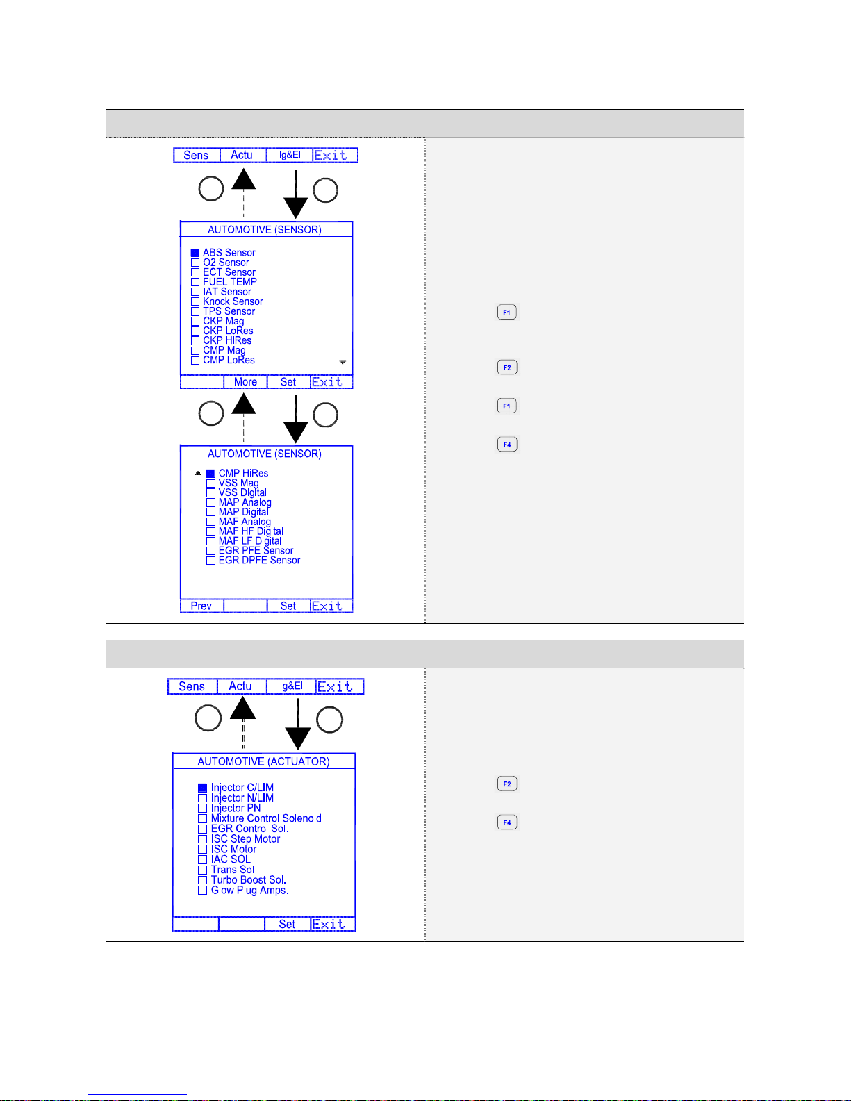
1.13.Sensor tests
1
4
2
3
①Press key to display automotive sensor
tests.
②Press key for more sensor tests.
③Press key for previous sensor tests.
④Press to exit.
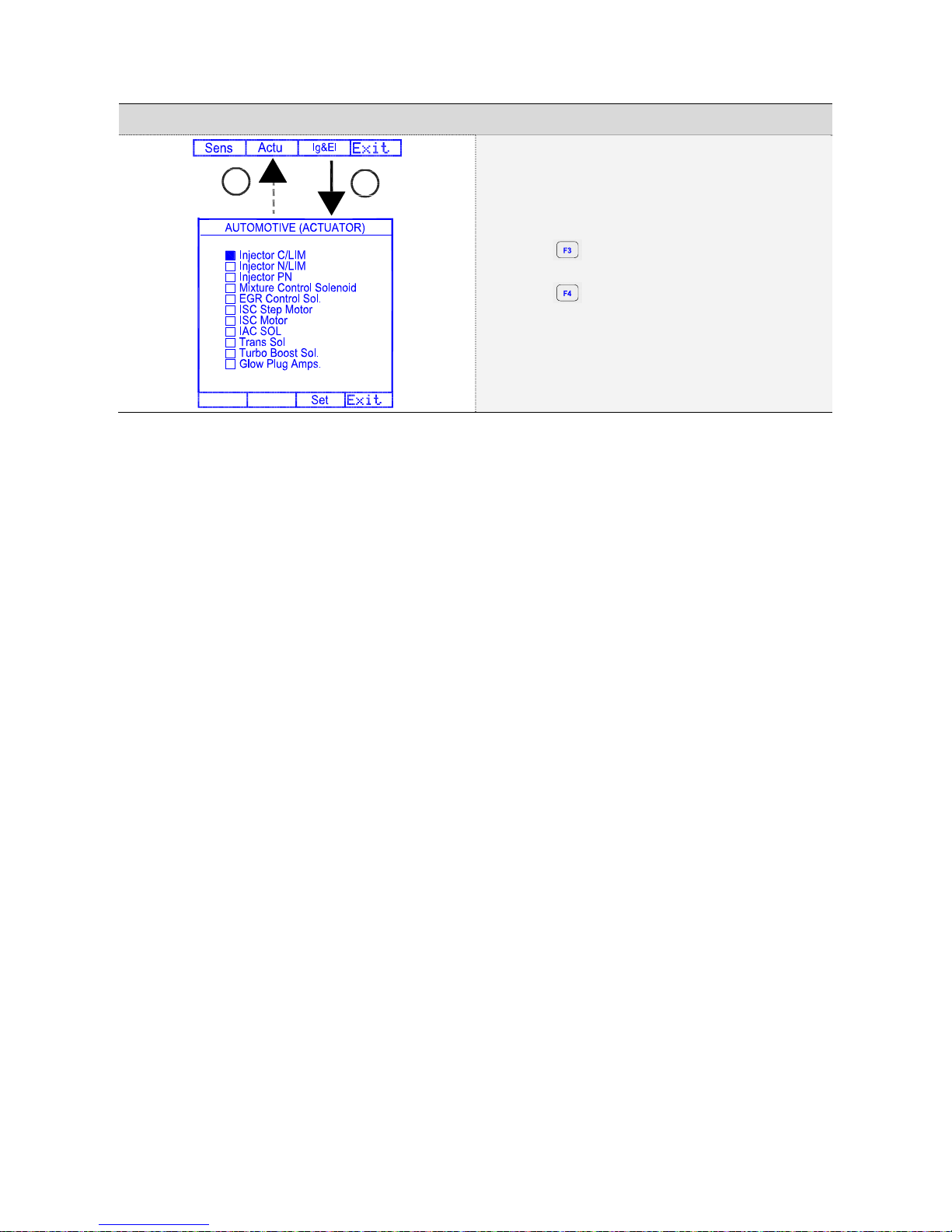
1.14.Actuator tests
1
2
①Press key for Actuator tests.
②Press to exit.
1-8
1.15.Ignition & Electrical
1
2
①Press key for Ignition & Electrical tests.
②Press to exit.
2-9
2. Test Examples
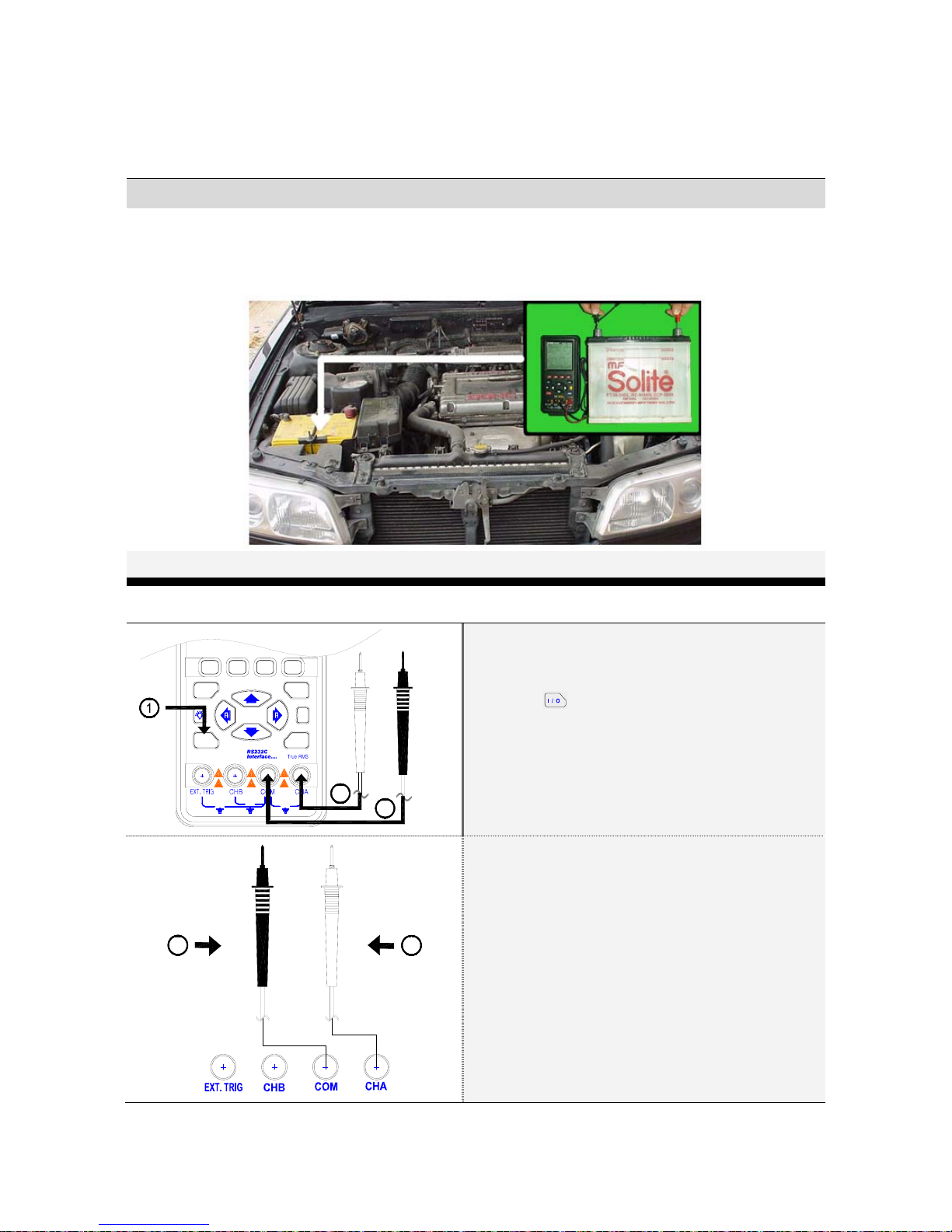
2.1. Battery Voltage test
Battery location and test
?
I / O
600V
MAX
600V
MAX 600V
MAX
FUNC
DIV
F1 F2 F3 F4
TRIG
2
3
Pr①ess for about 2 sec. to turn on the
meter.
Insert the black lead in the COM input②sockets.
Insert the red lead in the CHA input③sockets.
Battery neg (-)
Battery pos (+)
5
4Connect the black probe to the negative (④-)
circuit or to ground.
Connect the red probe to the circuit com⑤ing
from the power source.
2-10
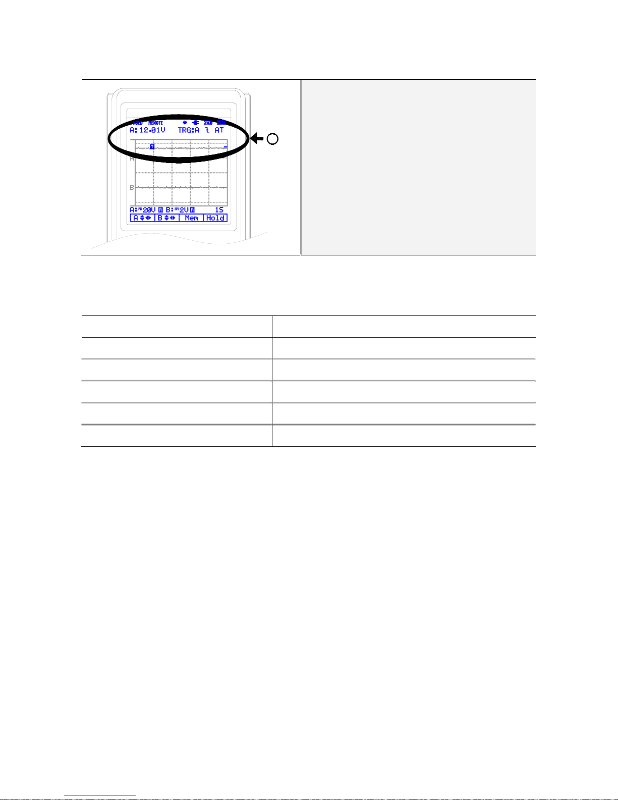
6
Check the measurement voltage.⑥
Note
If the meter reads negative, the battery has been reverse charged (has reversed polarity) and
should be replaced, or the meter has been connected incorrectly.
Battery voltage (V) State of charge
12.6 or higher 100% charged
12.4 75% charged
12.2 50% charged
12.0 25% charged
11.9 or lower Discharged
2-11
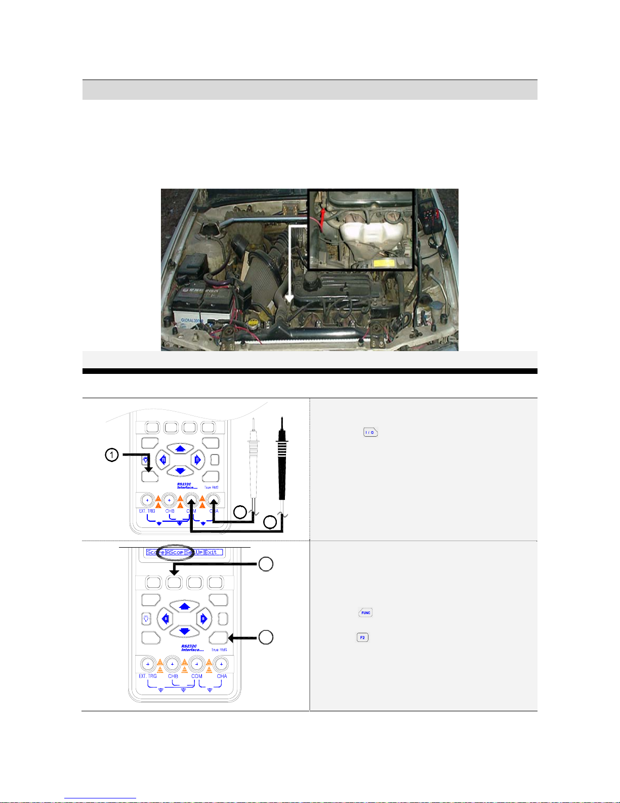
2.2. O2 Sensor (Oxygen Sensor)
O2 Sensor location and test
?
I / O
600V
MAX
600V
MAX 600V
MAX
FUNC
DIV
F1 F2 F3 F4
TRIG
2
3
Press①for 3 seconds to turn on the
meter.
Insert the black②lead in the COM input
sockets.
Insert the red lead in the CHA input sockets.③
?
I / O
600V
MAX
600V
MAX 600V
MAX
FUNC
DIV
F1 F2 F3 F4
TRIG
5
4
Press④.
Press⑤(ASCOP).
2-12
DIV
F1 F2 F3 F4
TRIG
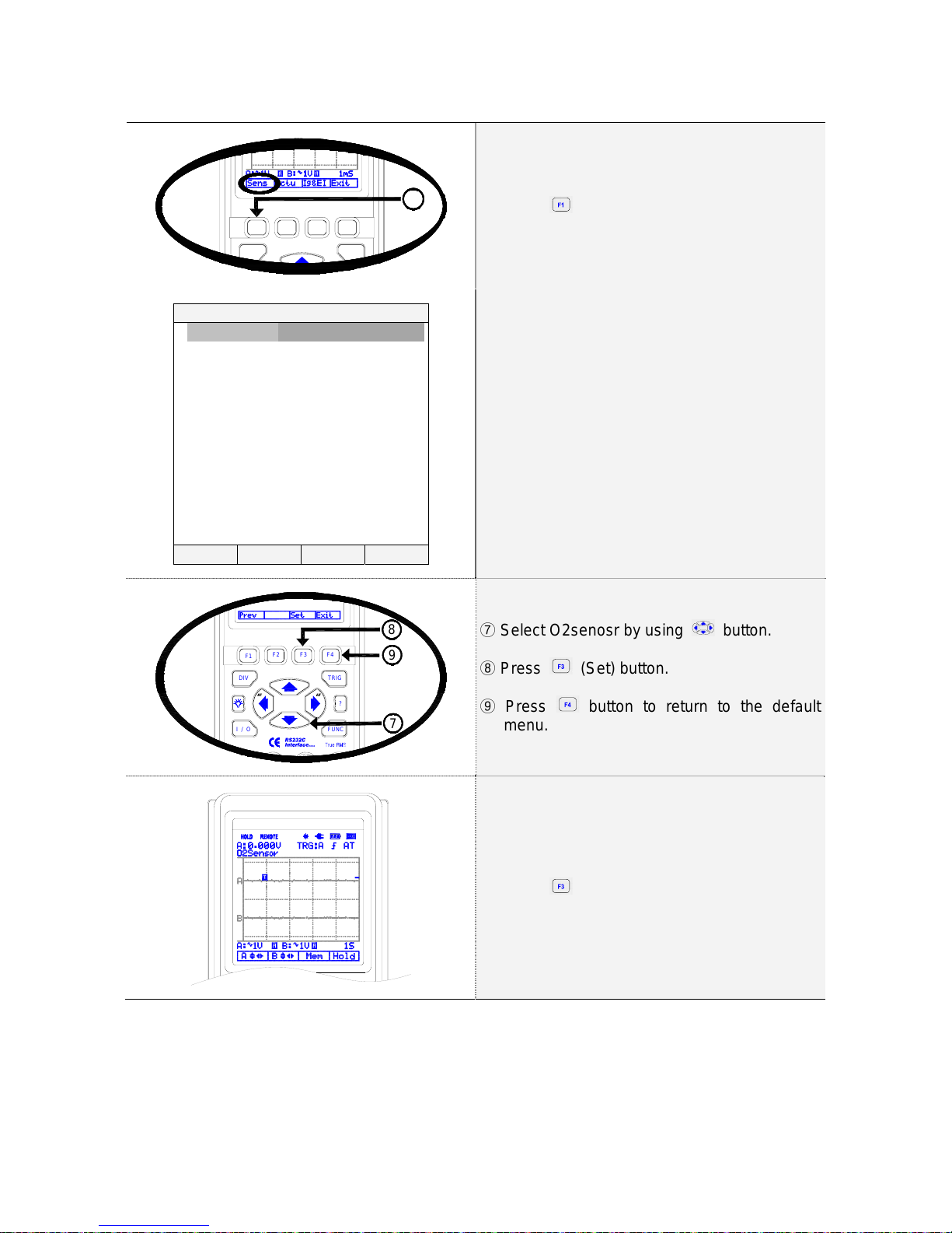
6
Press⑥(Sens)
AUTOMOTIVE (SENSOR)
□ABS Sensor
□O2 Sensor
□ECT Sensor
□FUEL TEMP
□IAT Sensor
□Knock Sensor
□TPS Sensor
□CKP Mag
□CKP LoRes
□CKP HiRes
□CMP Mag
□CMPLoRes ▼
Prev Set Exit
Automotive (SENSOR) is displayed as left.
?
I / O FUNC
DIV
F1 F2 F3 F4
TRIG
7
8
9
Select O2senosr by using⑦button.
Press⑧(Set) button.
Press⑨button to return to the default
menu.
Default menu is displayed as left.
Press⑩(MEM) button to display the
memory menu as below.
2-13
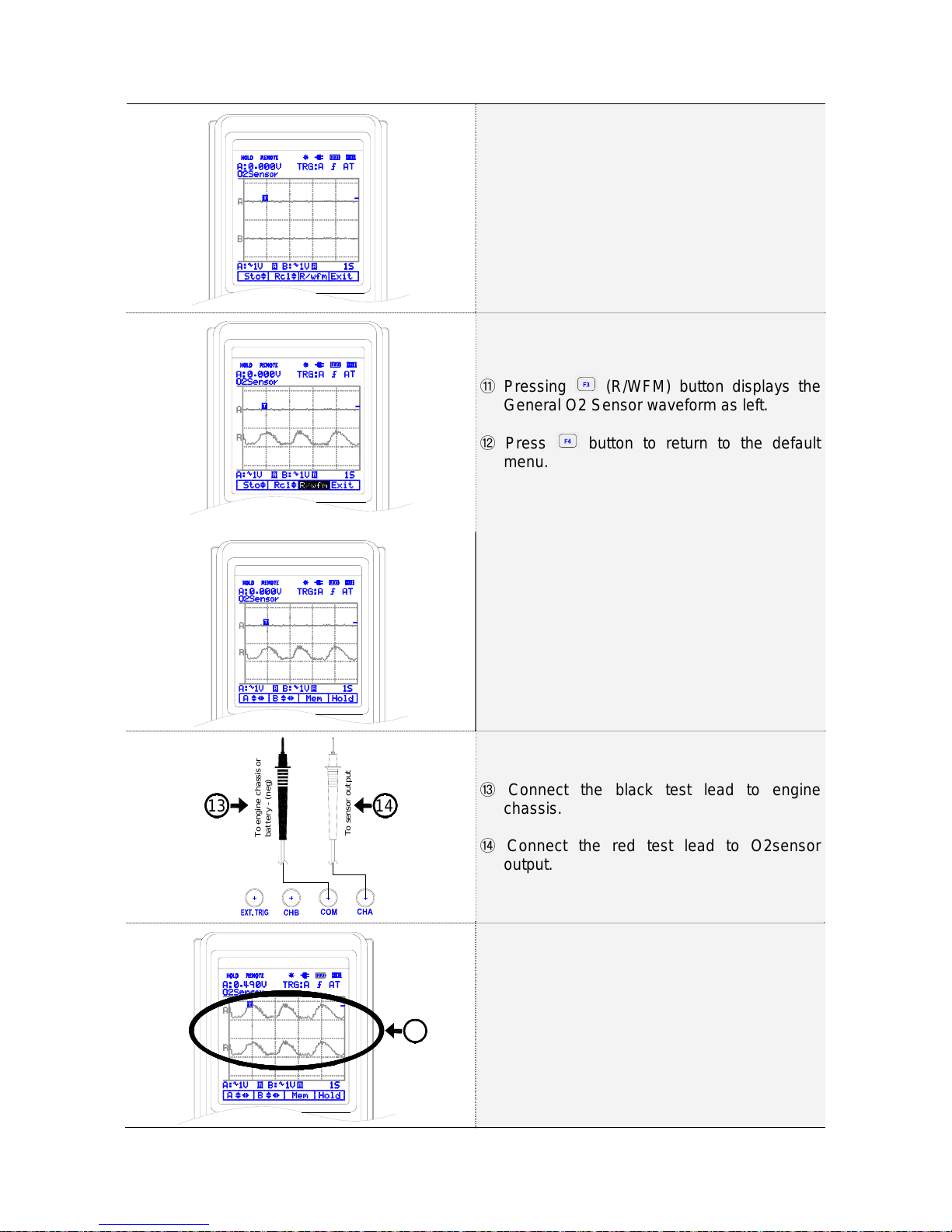
Memory menu is displayed as left.
Pressing⑪(R/WFM) button displays the
General O2 Sensor waveform as left.
Press⑫button to return to the default
menu.
O2 sensor waveform is displayed in the default
menu.
To engine chassis or
battery - (neg)
To sensor output
1413 Connect the black test lead to engine⑬chassis.
Connect the red test lead to O2sensor⑭output.
15 Compare measurement waveform with⑮general O2 Sensor waveform.

2-14
Note
1) Refer to Easy manual for changing the Vertical division or Horizontal division.
2) Refer to Easy manual for triggering on a waveform.
Note
The oxygen sensor output voltage is used to control the fuel system air/fuel ratio. The output of
the sensor varies depending on the oxygen level sensed in the engine exhaust gases and the
operation of the closed loop fuel system.

3-1
3. Introduction
3.1. Main Features
This Programmable Automotive Scope Meter offers enhanced features that similar type test
instruments on the market today don't have.
All the functions are designed to be very convenient to use. You can quickly get used to working
with this METER and the great many functions integrated inside. This instrument features:
No Features
1 RS-232C interface for transferring measurement data and waveform.
2 45 short reference waveform memory:
3 Dual Channel and Auto Calibration.
4 Automatically setting for horizontal and vertical division.
5 Sampling Time: Single CH: 50MHz, Dual CH: 25MHz
6 DC to 1MHz oscilloscope band width
7 Built-in auto ranging True-RMS digital MultiMeter.
8 Test for checking component signals on sensor, actuators, ignition and electrical.
9 Real time Update and Auto range.
10 Data holds and run mode.
11 Back light display and Low battery indication.
12 Display Type: Super-Twist 132 x 128 pixels.
13 Designed to comply with safety standard for UL3111, CSA C22.2 No.1010-1
3.2. Unpacking the Test Tool Kit
The following items are included in your test tool kit.
■STANDARD ■OPTION
# Description <Cont.>
1 Industrial Scope Meter Test Tool <1>
2 Holster <1>
3 Li-ION Battery Pack (installed) <1>
4 AC Power & Rechargeable Adaptor <1>
5 Test Leads <2>
6 Users Manual (this book) <1>
7 RS-232 Cable <1>
8 Scope Meter Software for Windows <1>
9 Carrying case <1>
#Description <Cont.>
1 Inductive Pick-up <1>
2 Capacitive Pick-up <1>
Note:
When new, the rechargeable Li-ION battery pack is not fully charged.
The accessories may be changed to improve the product quality without notifying the
customers.
Table of contents
Other Seintek Measuring Instrument manuals

Popular Measuring Instrument manuals by other brands


GW Instek
GW Instek GPM-001 user manual

Rigol
Rigol RSA5000-VNA user guide

Kestrel
Kestrel 1000 user guide

Geotech
Geotech EcoSense ODO200M user manual

Brüel & Kjær
Brüel & Kjær 2107 instructions & applications

Universal Laser Systems
Universal Laser Systems Laser Platform M-300 Installation and operation manual


