Energie Aquapura 14 HT Operating manual

USER AND INSTALLATION MANUAL
1
USER AND INSTALLATION MANUAL
EN
Aquapura HT
AQUAPURA 14HT (INVERTER P 6-16)
AQUAPURA 8HT (INVERTER P 3-10)
Directives:
2014/35/UE
2014/30/UE
Regulation nº 814/2013
Regulation nº 812/2013
Revision:6
Versão 2
Date: 11/07/2023

USER AND INSTALLATION MANUAL
2
Esteemed Client,
We would like to thank you for your choice when you acquired an equipment for sanitary
water heating.
AQUAPURA INVERTER HT14 aero-thermal system will surely meet all your expectations
and provide many years of comfort with maximum power saving.
Our organization dedicates much time, energy and economic resources in order to
develop innovations that will promote power saving in our products.
Your choice has demonstrated your good sense and concern with power consumption, a
matter that affects the environment.
We have taken on a permanent commitment to conceive innovative and efficient
products so that this rational use of energy can actively contribute to the preservation of
the environment and natural resources of the planet.
Keep this manual whose objective is to inform, alert and advise about the use and
maintenance of this equipment.
Our services are always at your disposal. Feel free to call upon us!

USER AND INSTALLATION MANUAL
3
INDEX
1. INFO....................................................................................................................................... 5
2. SAFETY INFORMATION ......................................................................................................... 5
2.1 Danger Info.................................................................................................................... 6
2.2 Warnning Info................................................................................................................ 7
3. GENERAL INFO ...................................................................................................................... 7
3.1 Manufacturer Responsibility......................................................................................... 7
3.2 Installer responsibility ................................................................................................... 7
4. TRANSPORT........................................................................................................................... 8
5. PRINCIPLE OF OPERATION.................................................................................................... 9
6. UNIT OVERVIEW ................................................................................................................... 9
7. UNIT DIMENSIONS.............................................................................................................. 10
7.1. Aquapura 8HT................................................................................................................... 10
7.2. Aquapura 14HT ................................................................................................................ 11
................................................................................................................................................. 11
8. PERFORMANCE ................................................................................................................... 12
8.1 AQUAPURA 8HT .......................................................................................................... 14
8.2 AQUAPURA 14HT ........................................................................................................ 15
9. ETCHNICA INFO................................................................................................................... 12
10. INSTALLATION................................................................................................................. 16
10.1 Installation place ......................................................................................................... 16
10.2 Condensate drainage .................................................................................................. 16
10.3 Hydraulic installation................................................................................................... 17
10.4 Water filter.................................................................................................................. 17
10.5 Circuit water quality.................................................................................................... 18
10.6 Glycol (%)..................................................................................................................... 18
10.7 Temperature probes info ............................................................................................ 19
11. ELECTRICAL REQUIREMENTS .......................................................................................... 19
10.1 Main specifications...................................................................................................... 19
10.2 Electrical main spcifications/ protection devices........................................................ 20
10.3 Connection between external unit and display (user interface) ................................ 20
10.4 Connection terminals - Inputs..................................................................................... 21
10.5 Digital input configuration .......................................................................................... 22
10.6 Connections terminals –Outputs................................................................................ 23
12. ROOM THERMOSTAT INSTALLATION............................................................................. 23
13. MAIN CONTROLLER --- USER INTERFACE ....................................................................... 24
12.1 User interface description........................................................................................... 24
12.2 Unlock screen.............................................................................................................. 25

USER AND INSTALLATION MANUAL
4
12.3 Operation mode switch............................................................................................... 26
12.4 Setting target temperature ......................................................................................... 26
12.5 Setting interface display and function ........................................................................ 27
12.6 Time setting................................................................................................................. 28
12.6.1 System time setting................................................................................................. 28
12.6.2 Mute timer setting .................................................................................................. 29
12.6.3 Power timer setting................................................................................................. 29
12.7 Temperature curve...................................................................................................... 29
12.8 Color display calibration.............................................................................................. 30
12.9 Electric Heating ........................................................................................................... 30
12.10 Status interface display ........................................................................................... 31
12.11 Fault list ................................................................................................................... 32
14. MAIN CONTROLLER –INSTALLER INTERFACE................................................................. 32
13.1 Installer parameters.................................................................................................... 33
13.2 Compensation curve - Outdoor temperature Vs setpoint .......................................... 35
13.3 Output/ input state of digital / analogic contacts....................................................... 35
13.4 Info of software version .............................................................................................. 36
15. ALARM ............................................................................................................................ 36
13.1 Alarm –Electronic control fault table ......................................................................... 36
13.2 Alarm –Frequency conversion board fault table........................................................ 38
16. TROUBLESHOOTING ....................................................................................................... 39
17. APPENDIX 1 –HYDRAULIC SCHEMES ............................................................................. 41
15.1 Hydraulic schemes glossary ........................................................................................ 41
15.2 Central Heating and Cooling ....................................................................................... 41
15.3 Central Heating and Cooling with buffer tank ............................................................ 43
15.4 Central Heating and Cooling with buffer tank + DHW ................................................ 43
15.5 Central Heating and Cooling + DHW ........................................................................... 44
15.6 Domestic hot water..................................................................................................... 45
18. WARRANTY ..................................................................................................................... 45
USER AND INSTALLATION MANUAL
5
1 INFO
This manual is intended as an aid to qualified service personnel for proper installation, operation
and maintenance of the Heat Pump.
Read this manual carefully before attempting to install or operate the Heat Pump. Failure to
follow these instructions may cause a fault of the Heat Pump, resulting in electrical shock, scald
injury and/or property damage.
Installer:
Before leaving the premises, review this manual to be sure the Heat Pump has been installed
correctly.
Start or operate the unit and check that the parameters are within the normal operating range.
2 SAFETY INFORMATION
To prevent the users and others from the harm of this unit, and avoid damage on the unit or
other property, and use the heat pump properly, please read this manual carefully and
understand the following information correctly.
The piping connection and wiring should be installed according to the local legal laws and
regulations as well as the qualified professional.
DANGER
Any process that the supplier believes may pose a danger of personal injury
and/or material damage must be marked with a DANGER SIGN.
As a means of further classifying the hazard, the symbol will be accompanied
by one of the following words:
• DANGER: when the operator and/or people in the vicinity of the equipment
are subject to personal injury.
• ATTENTION: when nearby equipment and/or materials are subject to
material damage.
INFO
All information that the supplier believes can contribute to the best
performance and conservation of the equipment must be marked with the
information sign.
WARNNING
Children must not play with the device.
Cleaning and maintenance must not be carried out by children without
supervision.
This appliance can be used by children aged 8 years and over and by people
with limited physical, sensory or mental capabilities or lack of experience and
knowledge if they are supervised or have received instructions concerning the
use of the appliance in a safe way and understand the risks involved;

USER AND INSTALLATION MANUAL
6
2.1 Danger Info
INSTALLATION:
Description
DANGER
The heat pump must be installed by qualified personals, to avoid improper
installation which can lead to water leakage, electrical shock or fire.
Please make sure that the unit and power connection have good earthing, otherwise
may cause electrical shock.
Unit refrigerant is flammable.
•Carry out brazing or welding only on empty pipes, free from any residual
lubricating oil;
•Do not place flames or other heat sources near pipes that contain
refrigerant;
•Do not operate with an open flame near the unit;
HP RUNNING:
Description
It is prohibited to place fingers, hands or other objects on the fans. Failure to do so
can cause serious injury or equipment destruction.
DANGER
When there is something wrong or strange smell, the power supply needs to be
shut off to stop the unit. Continue to run may cause electrical short or fire.
MAINTENANCE:
Description
DANGER
When the heat pump need to be moved or installed again, please entrust dealer or
qualified person to carry it out. Improper installation will lead to water leakage,
electrical shock, injury or fire.
DANGER
Maintenance or repairs must be carried out by the seller or qualified technician.
Improper intervention could cause water leakage, electric shock, injury or fire.
The user is prohibited from carrying out any intervention at HP. Failure to do so
can cause water leakage, electric shock, serious injury or fire.

USER AND INSTALLATION MANUAL
7
2.2 Warnning Info
INSTALLATION:
Description
DANGER
The unit CANNOT be installed near the flammable gas. Once there is any
leakage of the gas, fire can occur.
Make sure that the basement of the heat pump is strong enough, to avoid
any decline or fall down of the unit.
Make sure that there is circuit breaker for the unit, lack of circuit breaker
can lead to electrical shock or fire.
MAINTENANCE:
Description
PERIGO
Please switch off the power for clean or maintenance.
It is expressly prohibited to make any type of chamfering in the
protection fuses.
Fuses must be replaced by a qualified person.
Do not spray BC with flammable liquids, it may cause fire.
Do not use any cleaning agents containing sand, soda, acid or chloride as
these may damage the surface.
3 GENERAL INFO
3.1 Manufacturer Responsibility
Our products are produced according to the requirements of various European Standards.
Always concerned with the quality and performance of our products, we strive continuously to
improve them. Therefore, we reserve to the right to modify at any time the information described
herein.
As manufacturers we are no longer responsible for the malfunction or even damage of the
equipment when:
•The instructions for use are not respected.
•The installation instructions are not respected.
•Lack of maintenance (if required).
3.2 Installer responsibility
The installer is responsible for proper installation of the equipment and start with its operation.
The installer should note the following notes:

USER AND INSTALLATION MANUAL
8
•Carefully read and follow the instructions of the manuals supplied with the equipment;
•Do the installation in accordance with the standards and requirements given by the
manufacturer;
•Do the initial startup of the equipment and check all control points:
•Explain to the user how to do the installation and how to use the equipment;
•Warn the user of the obligation to make the checking and maintenance of the
equipment when necessary;
•Supply to the user all the documents provided with the equipment (manual and
warranty datasheet).
4 TRANSPORT
The Heat Pump is packed in a cardboard box without a bottom, and is secured to a wood pallet
with plastic strapping.
When the heat pump is transported, please keep the unit stand up, otherwise the inner parts of
the device may be damaged.
The unit should be transported to the final installation site on a wooden pallet, during transport
the heat pump must not be tilted more than 45 (in either direction).
The recommended tools to transport the equipment while it is still on the pallet can be: forklift
or pallet.
When transporting the unit make sure that you lift it only from the bottom and always with the
unit placed on the pallet. Do not move the unit without assistance.
USER AND INSTALLATION MANUAL
9
Description
WARNNING
The unit has been tested and inspected prior to shipment from the
manufacturer for quality assurance. Carefully inspect the equipment
components upon receipt to ensure that the equipment has not been
damaged in transit.
Confirm that all ordered parts have been received as specified and that unit
type, size, and voltage are correct.
5 PRINCIPLE OF OPERATION
Ambient air is drawn in by the fan and passed over the evaporator. The evaporator cools the air,
i.e. it extracts the heat it contains. In the evaporator, the heat removed is transferred to the
working fluid (refrigerant).
With the aid of an electrically driven compressor, the absorbed heat is "pumped" to a higher
temperature level through an increase in pressure and given off to the heating water via the
condenser (heat exchanger).
In so doing, the electrical energy is used to raise the heat of the environment to a higher
temperature level.
Due to the fact that the heat energy extracted from the air is transferred to the heating water,
this type of appliance is referred to as an air to water heat pump.
The air to water heat pump consists of the following main components: Evaporator, fan,
expansion valve, low-noise scroll compressor, condenser and the control unit.
In the case of low ambient temperatures, air humidity may accumulate on the evaporator in the
form of frost, impairing the heat transfer. The evaporator is automatically defrosted by the heat
pump, as required, with the possibility of vapor plumes forming at the air outlet.
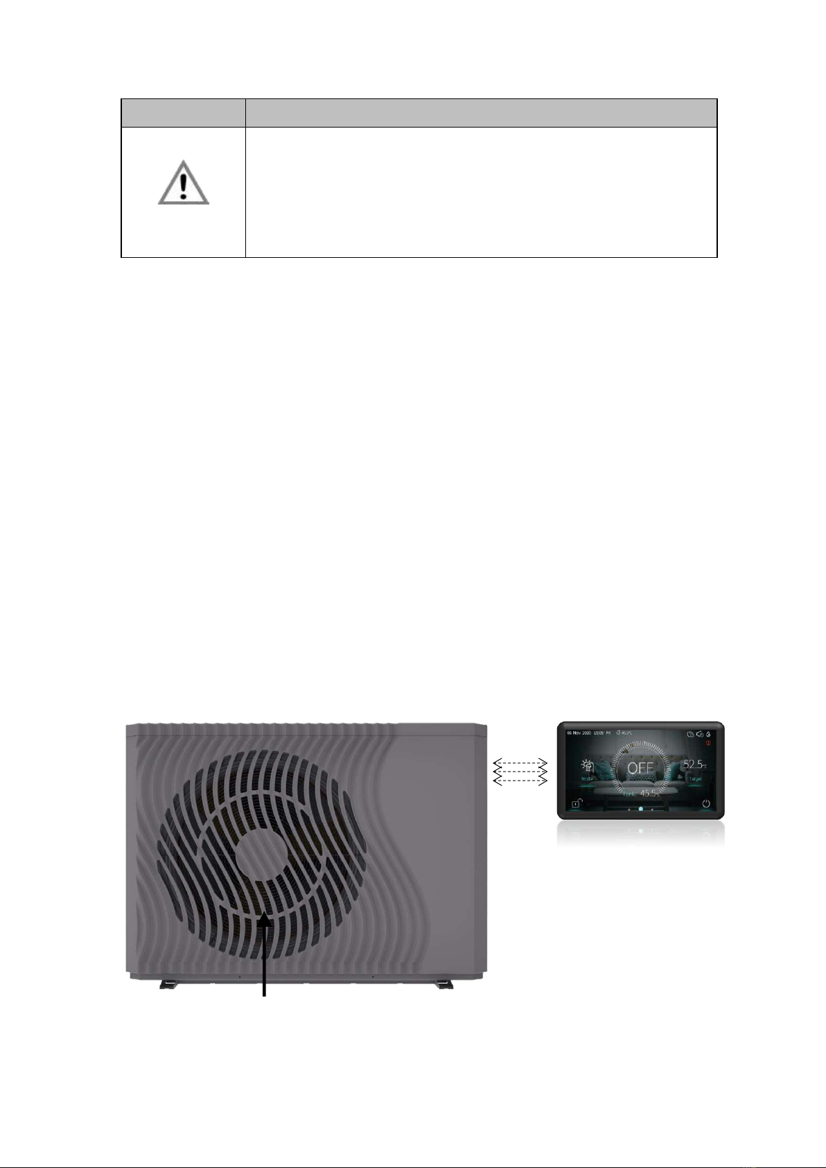
6 UNIT OVERVIEW
Display (user interface)
Air outlet (horizontal)

USER AND INSTALLATION MANUAL
10
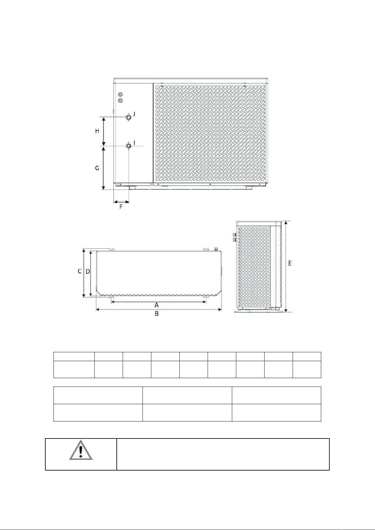
7 UNIT DIMENSIONS
7.1 Aquapura 8HT
~
A
B
C
D
E
F
G
H
Dimension
(mm)
830
1167
445
428
795
166
339
229
I
(Inlet Water)
J
(Outlet Water)
Dimension
(Inches)
1”
1”
J
I
E
USER AND INSTALLATION MANUAL
11
7.2 Aquapura 14HT
A
B
C
D
E
F
G
H
Dimension
(mm)
975
1287
500
458
928
125
363
238
I
(Inlet Water)
J
(Outlet Water)
Dimension
(Inches)
1”
1”
INFO
All the units are represented in millimeters

USER AND INSTALLATION MANUAL
12
8 TECHNICAL INFO
1) Air temperature (DB/WB) 7°C/6°C; Water temperature (inlet/outlet) 30°C/35°C
2) Air temperature (DB/WB) 35°C/ 24°C; Water temperature (inlet/outlet) 12°C/ 7°C
Aquapura 8HT (Inverter P3-10)
Powe supply
/
240V~/50Hz
Refrigerant / Charge
/ Kg
R290 / 0,500 / 0,0015
Heating
Heating capacity range (min/ max)
kW
3,0 ~ 10,3
Electrical power range
kW
0,71 ~ 2,9
Rated thermal power supplied ¹
kW
7,2
Rated electrical power consumption¹
kW
1,5
COP¹
/
4,8
Cooling
Cooling capacity range (min / max)
kW
1,6 ~ 8,51
Electrical power range
kW
0, 78 ~ 2,95
Rated thermal power supplied 2
kW
5,7
Rated electrical power consumption 2
kW
1,64
EER²
/
3,47
Technical specifications
Maximum temperature –heating
ºC
70
Backup electrical heater
/
Não integrado
Maximum operating current
A
13,5
Maximum power consumed
kW
3,0
Number of compressors
/
1
Compressor typology
/
DC Inverter
Water pump
/
Integrada/ 5
Minimum water flow
m3/h
1,0
Internal water pressure drop
kPa
20
Number of fans
/
1
Hydraulic connections (inlet/outlet)
Pol.
1’’ / 1’’
Sound pressure at 1m
dB(A)
43
Sound Power
dB
57
Net weight
Kg
80
Net dimensions (L/ A/ P)
mm
795/ 1167/ 455
Erp / Performance in accordance with EN 14825 –Average climate
Energy efficiency class (35°C)
%
A+++
SCOP
/
5,02
Energy efficiency class (55°C)
A++
SCOP
3,73

USER AND INSTALLATION MANUAL
13
Aquapura 14HT
Aquapura 14HT-T
Powe supply
/
240V~/50Hz
400V~/3P+N/50Hz
Refrigerant / Charge/CO2 Eq.
/ Kg/ton
R290 / 0,850/0,0025
Heating
Heating capacity range (min/ max)
kW
6,18~ 15,75
6,18~ 15,75
Electrical power range
kW
1,45 ~ 4,67
1,45 ~ 4,67
Rated thermal power supplied ¹
kW
11,85
11,85
Rated electrical power consumption¹
kW
2,36
2,36
COP¹
/
5,02
5,02
Cooling
Cooling capacity range (min / max)
kW
3,35 ~ 11,61
3,35 ~ 11,61
Electrical power range
kW
1,52 ~ 4,98
1,52 ~ 4,98
Rated thermal power supplied 2
kW
7,85
7,85
Rated electrical power consumption 2
kW
1,98
1,98
EER²
/
3,96
3,96
Technical specifications
Maximum temperature –heating
ºC
70
70
Backup electrical heater
/
Not provided
Not provided
Maximum operating current
A
24,5
10,5
Maximum power consumed
kW
5,3
5,3
Number of compressors
/
1
1
Compressor typology
/
DC Inverter
DC Inverter
Water pump
/
Integrated
Integrated
Minimum water flow
m3/h
1,6
1,6
Internal water pressure drop
kPa
30
30
Number of fans
/
1
1
Hydraulic connections (inlet/outlet)
Pol.
1’’ / 1’’
1’’ / 1’’
Sound pressure at 1m
dB(A)
42
42
Sound Power
dB
58
58
Net weight
Kg
160
160
Net dimensions (L/ A/ P)
mm
1287/ 928/ 485
1287/ 928/ 485
Erp / Performance in accordance with EN 14825 –Average climate
Energy efficiency class (35°C)
%
A+++
A+++
SCOP
/
5,13
5,13
Energy efficiency class (55°C)
A+++
A+++
SCOP
3,97
3,97
1) Air temperature (DB/WB) 7°C/6°C; Water temperature (inlet/outlet) 30°C/35°C
2) Air temperature (DB/WB) 35°C/ 24°C; Water temperature (inlet/outlet) 12°C/ 7°C

USER AND INSTALLATION MANUAL
14
9 PERFORMANCE
9.1 AQUAPURA 8HT
Heating Capacity
Water temperature (inlet/outlet) 30°C/35°C
COP
Water temperature (inlet/outlet) 30°C/35°C
0
2
4
6
8
10
12
14
-15 -10 -7 -5 0 2 7 10 15 20 25
Heating Capacity kW
Ambient temperature °C
0,00
1,00
2,00
3,00
4,00
5,00
6,00
7,00
-15 -10 -7 -5 02710 15 20 25
COP
Ambient temperature °C

USER AND INSTALLATION MANUAL
15
9.2 AQUAPURA 14HT
Heating capacity
Average climate (DB/WB) 7°C/6°C; Water temperature (inlet/outlet) 30°C/35°C
COP
Average climate (DB/WB) 7°C/6°C; Water temperature (inlet/outlet) 30°C/35°C
0
2
4
6
8
10
12
14
16
18
-15 -12 -8 -5 -2 0 2 5 7 12 15 18 21 25
Heating Capacity kW
Ambient Temperature °C
0
1
2
3
4
5
6
7
8
-15 -12 -8 -5 -2 0 2 5 7 12 15 18 21 25
COP
Ambient Temperature °C
USER AND INSTALLATION MANUAL
16
10 INSTALLATION
10.1 Installation place
Before starting any installation procedure, check that the base of the place where the equipment
will be placed is perfectly level. This prevents the compressor lubricating oil from working outside
the indicated levels.
Look for a place with an even, safe and resistant floor, preferably in concrete, taking into account
the weight of the machine. At a minimum, the concrete base should have a thickness of 150mm
and if possible above ground level (100mm)
During its operation, the heat pump can create water originated by the condensation of the
evaporator, being necessary to prepare the installation site with a drain point to facilitate its
drainage.
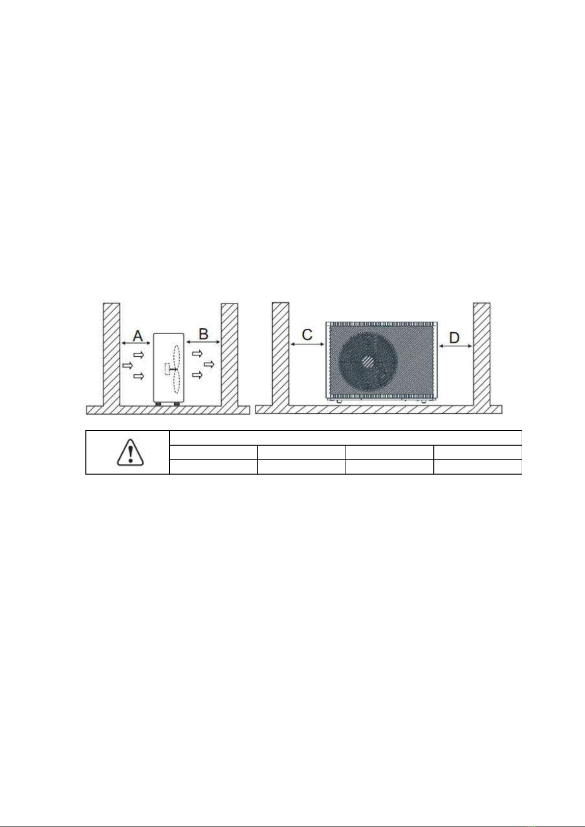
Another important point is the minimum distances that the equipment must comply with in
relation to walls, ceilings or any type of obstacles that may impair its performance and make
access difficult, both during installation and in any maintenance operations.
Requirements
A
B
C
D
>500mm
>1500mm
>1000mm
>500mm
The walls and roof of the technical room can be insulated with sound absorption panels if the
noise level of the heat pump is too high.
The feet of the HP must be fixed to the base, preventing the equipment from moving with the
vibrations caused by its normal operation.
10.2 Condensate drainage
In normal operation, water is produced as a result of condensation in the evaporator and defrost
cycles. Prepare a good drainage system to prevent the formation of ice on the floor, thus avoiding
possible falls. The drain tube must have a diameter of min. 50mm, the water discharge must be
carried out to the sewer and must not be exposed in places with frost formation.

USER AND INSTALLATION MANUAL
17
10.3 Hydraulic installation
Take the following points into account when executing the hydraulic circuit:
•Reduce as much as possible the number of bends in the pipes to reduce pressure drops
in the installation;
•Ensure system fittings, dowels, water pumps and valves are designed for full flow through
the facility. Obstructions can impact the unit's performance and the effectiveness of the
central heating system;
•The piping must be free from dirt, if possible, clean the installation;
•Load the installation to check for possible leaks and then isolate the entire installation;
•Place an expansion vessel in the installation, the pressure in the expansion vessel must
be 0.5 bar higher than that of the installation;
•Check if the equipment's flow switch is working properly. Simulate a flow failure by
closing a strainer and check if the controller stops the BC operation and issues an alarm
message;
•The hydraulic connections between the BC and the central heating circuit must be made
with a flexible tube to avoid the transmission of vibrations;
•Before putting the BC into operation, check that the hydraulic circuit is full and properly
bled. If the hydraulic circuits are sectioned, each circuit must be bled, ensuring that it
eliminates all air pockets in the installation;
•Place a thermometer and a pressure gauge at the water inlet and outlet to facilitate
inspection;
•The pressure placed on the hydraulic circuit must be between the following values: Min.
1.5 bar and Max. 2 bar.
warnning
The hydraulic connection should be installed according to the local legal
laws and regulations as well as the qualified professional
10.4 Water filter
The filter allows block any impurities present in the hydraulic circuits. Residue left in the heater
pipes will damage the heat exchangers and cause the heat pumps to malfunction. It is
recommended install the filter in the heater return line, especially if no buffer storage is present.
It is indispensable in order to prevent serious damage to the heat exchanger.
Note 1: The filter must contain a filtering mesh with holes that do not exceed one millimeter.
Note 2; The filter should be kept cleaned and inspected periodically to maintain your condition,
cleanliness and ensuring the proper functioning of Heat pump

USER AND INSTALLATION MANUAL
18
10.5 Circuit water quality
The composition and quality of the water in the system has a direct effect on the performance of
the entire system and the lifetime of the heat pump.
For the initial charging and backfill of the system, usually normal tap water with a pH value of 7-
8 can be used as long as the water is not highly corrosive (chloride content > 150 mg/l) or hard
(>14°dH; degree of hardness IV). A drinking water analysis can be requested from the local water
supply company.
If the specific system volume is greater than 25 liters/kW heating output (e.g. through the
installation of a hot water buffer storage), then the maximum permissible calcium carbonate
input from the charging and backfilling water should be calculated in accordance with the VDI
guideline 2035. In some cases the charging water has to be softened.
Criteria
Max. value
Effects of non-compliance
PH - Wert
7-8
Danger of corrosion in boiler parts and heating
system
Degree of
hardness
< 14dH
- Increased lime deposits
- Reduced lifetime of boiler
Chloride content
< 150mg/l
Corrosion of alloyed materials
10.6 Glycol (%)
Glycol is used as an effective antifreeze in cooling and heating applications.
The percentage of glycol to be added to the hydraulic circuit is calculated as a function of the
ambient air temperature, considering for this purpose -5 °C. Using this value as a reference, the
installer must add 20% Ethylene Glycol to the hydraulic circuit.
USER AND INSTALLATION MANUAL
19
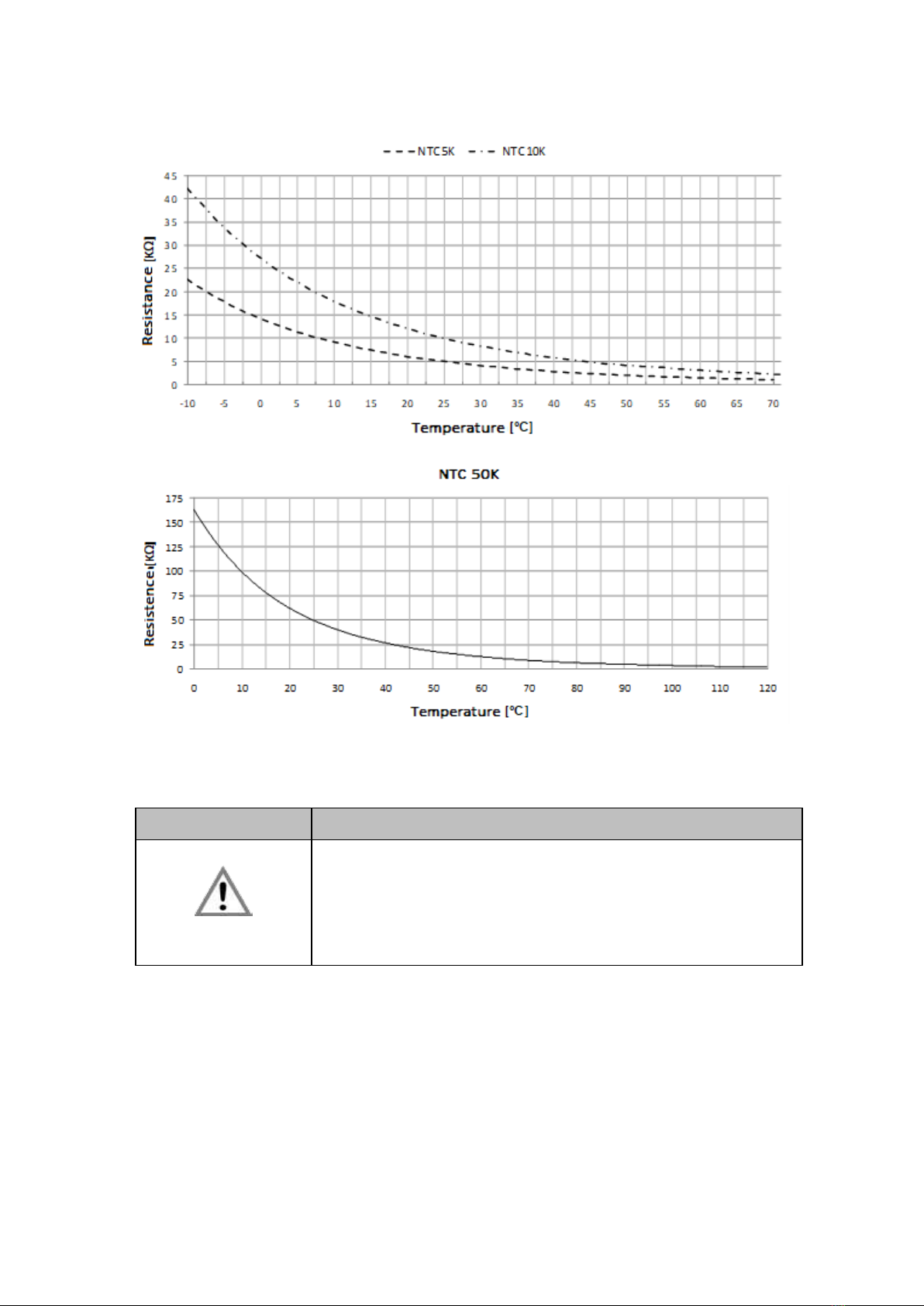
10.7 Temperature probes info
11 ELECTRICAL REQUIREMENTS
11.1 Main specifications
Description
WARNNING
•The installation of the electrical network must be carried out in
accordance with local regulations in force and by a qualified
professional.
•The installer must not make any kind of electrical changes to
the equipment.
Before making any type of connection, check that the supply voltage matches the characteristics
of the appliance.
The equipment must be connected directly to the general electrical distribution board. Dedicated
protection systems must be installed for the BC (circuit breaker and differential), connecting the
equipment together with others can cause voltage drops, impairing the equipment's operation.
Pay attention to the losses caused by the device's power cables, the smaller the cable section
area, the smaller the recommended maximum length. Make a note of the reference values for
the electrical consumption of the equipment and the distance from it to the power supply and
consult an electrician for advice on the diameter and type of cable to be used.

USER AND INSTALLATION MANUAL
20
To make the electrical connection, open the side panel and connect the general power cable in
the indicated places.
Description
WARNNING
•The equipment must be earthed in accordance with the
relevant regulations.
•The manufacturer is not responsible for any damage caused by
the equipment's lack of earth connection or by an anomaly in
the electrical supply.
11.2 Electrical main spcifications/ protection devices
Model
Power source
Max. current
* cable section
Aquapura 8HT
240V/50Hz
14A
2,5mm2
Aquapura HT 14
240V~ /50Hz
25 A
4 mm²
Aquapura HT 14 T
400V~/ 50Hz
11 A
2,5 mm2
The section of the wires above was selected in accordance with current regulations, considering
a cable distance of 10 meters.
NOTE: Follow local regulations when selecting ground wires and circuit breakers.
Select protection systems according to the following table:
Model
Power source
Max. current
CB
ELB
(nº pólos/A/mA)
Auapura 8HT
240V~/50Hz
14A
20A
1F+N/20/30
Aquapura HT 14
240V~/50Hz
25 A
32 A
1F+N/ 32/ 30
Aquapura HT 14 T
400V~/ 50Hz
11A
16 A
3F+N / 16/ 30
CB - Circuit Breaker; ELB –Differential
11.3 Connection between external unit and display (user interface)
The equipment is supplied with a 12 meter cable to interconnect the outdoor unit with the
display.
If the supplied cable is not long enough and the distance between the outdoor unit and the
display is less than 50 meters, we recommend installing a straight-through cable.
The cable must have at least 4 conductors with a section of 0,5mm and protected with a mesh
to avoid interference.
This manual suits for next models
1
Table of contents
Other Energie Inverter manuals


Popular Inverter manuals by other brands


BARRON
BARRON EXITRONIX Tucson Micro Series installation instructions

Baumer
Baumer HUBNER TDP 0,2 Series Mounting and operating instructions

electroil
electroil ITTPD11W-RS-BC Operation and Maintenance Handbook

Silicon Solar
Silicon Solar TPS555-1230 instruction manual

Mission Critical
Mission Critical Xantrex Freedom SW-RVC owner's guide

HP
HP 3312A Operating and service manual


