manuals.online logo
Brands
  1. Home
  2. •
  3. Brands
  4. •
  5. Studer
  6. •
  7. Inverter
  8. •
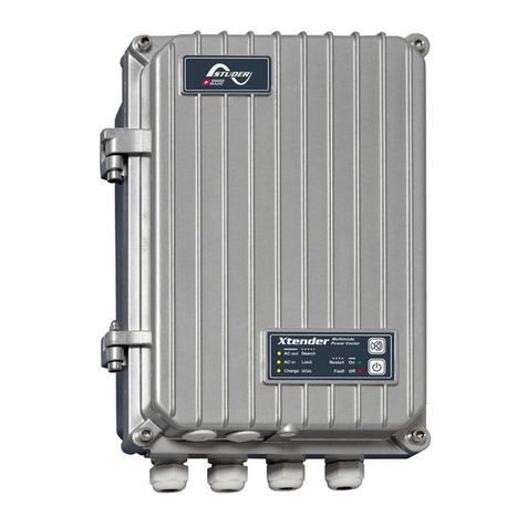
  9. Studer Innotec SA XTH 3000-12 User manual

Studer Innotec SA XTH 3000-12 User manual

Xtender
P.
V4.2.3Appendix 1
STUDER Innotec SASTUDER Innotec SA
User manual- Manuel utilisateur-Betriebsanleitung-Manual utilizador
XTH 3000-12
XTH 5000-24
XTH 6000-48
XTH 8000-48
XTM 1500-12
XTM 2000-12
XTM 2400-24
XTM 3500-24
XTM 2 00-486
XTM 4000-48
XT 00-12S 9
XT 00-S 12 24
XT 400-S 1 48
This appendix is part of the installation and user manual
Cette annexe fait partie intégrante du manuel d’utilisation
Dieser Anhang ist ein wesentlicher Bestandteil des Betriebsanleitung
Este anexo es parte integrante del manual de utilización
Appendix 1 Annexe 1 Anhang 1 Anexo 1
AC IN
L
AC OUT
N
Battery
+
-Remote
On/Off
CAN
Bus
Temp.
Sens.
Xtender
Aux2Aux1
L1
L2
L3
a
b
123
L N
1
G
T
BTS-01
(Command
entry)
Xtender
P.
V4.2.3Appendix 1
STUDER Innotec SA
Xtender
P.
V4.2.3Appendix 1
STUDER Innotec SA
1
NOTE IMPORTANTE
Cette annexe au manuel est commune à toutes les langues et doit être conservée avec le manuel
de la langue de votre choix.
Pour la bonne compréhension de ce document, vous devez vous référer aux commentaires des
éléments référencés par des lettres ou des chiffres dans les chapitres suivants du manuel :
Référence : chap. commentaires
Figures 16 Commentaire des figures de l’annexe
Lettres minuscules 17 Eléments des figures (partie DC)
Lettres majuscules 18 Eléments des figures (partie AC)
Chiffres 1 à 22 3.6.4 Descriptif des éléments du compartiment de câblage
Chiffres 25 à 29 19 Dimension mécanique et éléments de montage
Chiffres 30 à 40 20 Eléments de l’étiquette d’identification
IMPORTANT NOTE :
This appendix to the manual is common to all languages and must be kept with the manual of your
choice.
For the good understanding of this document, you should refer to the comments about elements
referenced by letters or numbers in the chapters of the manual mentioned in the below table:
Reference : Sect. Comments
Figures 16 Comments to drawings (Figures)
Lower-case characters 17 Drawing elements (DC side)
Upper-case characters 18 Drawing elements (AC side)
Number 1 to 22 3.6.4 Elements of the connection compartments
Number 25 to 29 19 Mechanical dimension and mounting elements
Number 30 to 40 20 Identification plate
WICHTIGE ANMERKUNG :
Dieser Anhang zum Bedienerhandbuch ist fèr alle Sprachen identisch und muss mit dem
entsprechenden Bedienerhandbuch aufbewahrt werden.
Für ein gutes Verstàndnis diese Dokuments halten Sie sich an die folgenden Kapitel des
Bedienerhandbuchs :
Referenz : kap. Kommentare
Figuren 16 Beschreibung zu den Abbildungen im Anhang
Alphabetische kleinbuchstaben 17 Abbildungskomponenten (Teil DC)
Alphabetische Grossbuchstaben 18 Abbildungskomponenten (Teil AC)
Nummer 1 bis 22 3.6.4 Elemente des Kabelanschlussfach
Nummer 25 bis 29 19 Abmessungen und Montageelemente
Nummer 30 bis 40 20 Einträge auf dem Typenschild
NOTA IMPORTANTE:
Este anexo al manual es común a todos los idiomas y debe conservarse con el manual del idioma
que ha elegido.
Para la buena comprensión de este documento, debe referirse a los capítulos siguientes del
manual:
Référencia : cap. comentarios
Esquemas (fig.) 16 Comentarios de las figuras del anexo
Caracteres en minúscula 17 Elementos de figuras (parte DC)
Caracteres en mayúscula 18 Elementos de figuras (parte AC)
Cifras 1 a 22 3.6.4 Descripción de los elementos del compartimento de
cableado del equipo
Cifras 25 a 29 19 Dimensiones mecánicas y elementos de montaje
Cifras 30 a 40 20 Elementos de la etiqueta de identificación
Xtender
P.
V4.2.3Appendix 1
STUDER Innotec SA
Xtender
P.
V4.2.3Appendix 1
STUDER Innotec SA
16A
IP54
Serial N°
XXMN 00002
XTS 1200-24
RoHS
COMPLIANT
2002/95/EC
800 VA / 1200VA
24Vdc / (18Vdc-34Vdc)
25Adc / 47Adc / 56Adc
230V / (150V-265V)
230V / (150V-245V)
Model:
Pnom*/P30*................
Pnom/P30..................
Uac Out......................
Iac In max...................
Uac In.........................
Idc Charge/Inv/Inv*....
Udc Battery................
Iac Out Inv/Inv* max.../
650 VA / 1000VA
3A / 3.5A / 18A
* = With ECF-01 option
[email protected]
WWW.studer-innotec.com
Fig. 1a
Model and
specification tag
32
33
34
35
36
37
38
39
40
UACin : .......
230V(150V-265V)
UBattery: .... 12V (9V-18V)
IAC in/out/Boost: ...
16A/ 6A / 22A
UACout: ......
230V(150V-265V)
Pnom/P30’:.. 500 VA / 1000VA
Model:....... XT S 1000-12
ICharge: ......
0- 30A
Ip54
[email protected]
WWW.studer-innotec.com
SWISSMAD E
CH-1950Sion
SN: ???? 0123
30
2
31
00352
SN:
XXFN
www.studer-innotec.com
[email protected]
RoHS
COMPLIANT
2002/95/EC
Model:
Pnom/P30.........
Udc Battery.......
Idc Charge/Inv..
3000VA / 3500VA
24Vdc (18Vdc-34Vdc)
90Adc / 165Adc
XTM 3500-24
Uac In..................
Iac In max............
Uac Out...............
230V (150V-265V)
50A
230V (150V-245V)
Iac Out Inv/max... 16A / 56A
IP20
30
33
34
35
36 39
37
38 40
32
33
34
35
36
37
38
39
30 32
XTH 5000-24
40
Xtender
P.
V4.2.3Appendix 1
STUDER Innotec SA
406 mm
463 mm
XTM
323 mm
256 mm 130mm
d=8mm
d=8mm
20cm
312 mm
205 mm
20cm
120 mm
306 mm
XTS
160mm
300mm
442mm
20cm
220mm
230mm
474mm
497mm
d=8mm
20cm
20cm
XTH
Fig. 2a
Dimension, clearance and affixing
27
25
26
d=8mm
3
84 mm
+
+
12V 12V
+ ++ +
+ + +
+ + +
+ + +
+ + +
+ + + +++
L
++ ++ + + + +
++++
++++
++ ++ + + + +
++
12V
24V
+
+
+
+
2V 2V 2V
2V 2V 2V
2V 2V 2V 2V 2V 2V
2V 2V 2V 2V 2V 2V
2V 2V 2V 2V 2V 2V
2V 2V 2V 2V 2V 2V
12V
12V
12V 12V
12V 12V 12V 12V
12V 12V 12V 12V
Fig. 5a Fig. 5b
Fig. 5c Fig. 5e
12V
12V
12V
12V
12V 12V
12V battery bank wiring
with 2Vcell in series and
parallel+series
12V battery bank
wiring with single and
parallel 12Vcell
24V battery bank wiring
with 2Vcell in serie and
parallel+series
24V battery bank
wiring with series and
series/parallel 12Vcell
4
++ ++ + + + +
++ ++ + + + +
2V 2V 2V 2V 2V 2V
2V 2V 2V 2V 2V 2V
++ ++ + + + +
++ ++ + + + +
2V 2V 2V 2V 2V 2V
2V 2V 2V 2V 2V 2V
Xtender
P.
V4.2.3Appendix 1
STUDER Innotec SA
+
12V
+
12V
+
12V
+
12V
+
12V
+
12V
+
12V
+
++ ++ + + + +
++ ++ + + + +
++
++ ++ + + + +
++ ++ + + + +
++
2V 2V 2V 2V 2V 2V
2V 2V 2V 2V 2V 2V
12V
12V 12V
12V 12V
2V 2V 2V 2V 2V 2V
2V 2V 2V 2V 2V 2V
2V 2V 2V 2V 2V 2V
Fig. 6a
Fig. 6b
Fig. 6c
Fig. 6d
48V battery bank wiring
with 2Vcell in series24 x s
48V battery bank
wiring with series
12Vcells
48V battery bank wiring with
series/parallel 12Vcells
48V battery bank
wiring with 2
prallelled strings
of 24 x 2V cells
5
++ ++ + + + +
++ ++ + + + +
++ ++ + + + +
++ ++ + + + +
2V 2V 2V 2V 2V 2V
2V 2V 2V 2V 2V 2V
2V 2V 2V 2V 2V 2V
2V 2V 2V 2V 2V 2V
2V 2V 2V 2V 2V 2V
++ ++ + + + +
++ ++ + + + +
++ ++ + + + +
++ ++ + + + +
2V 2V 2V 2V 2V 2V
2V 2V 2V 2V 2V 2V
2V 2V 2V 2V 2V 2V
2V 2V 2V 2V 2V 2V
2V 2V 2V 2V 2V 2V
+
12V
+
12V
+
12V
+
12V
P.
V4.2.2Appendix 1
Xtender
STUDER Innotec SA
AC IN
N
N
BATTERY
Temp.
max 300m
AC OUT
DSP
L1 L2
L3
L
6p
L
DC
AC
K1
K2
K3
K4
Fig. 7a
10
14
13
11
12
2
17
a
b
f
BTS-01
Xtender XTS principle and equivalent
schematic
6
f
t
Main
On/Off
Remote
entry
=
RCM-10
6p
1
6
Off
On
AC out
AC in
Charge
Search
Limit
U/Uo
Xtender
Multimode
Power Center
Fault
Restart
RJ45
RJ11
Com
Bus
Bus
termin.
8p8p6p
TO
23
4
6p
61
TCM-01 (XTS only)
RCM/10
RJ11
AUXILLARY
CONTACT
Aux2Aux1
8
ARM-02
6p6p
3
BTS-01
ARM-02
Remote Command Module
15
UPS
S/Boost
OFF/ON
OFF/ON
20
19
16
18
RPP
+
>1mF
RCC 02-
23
Xtender
P.
V4.2.3Appendix 1
STUDER Innotec SA
AC IN
N
N
BATTERY
Temp.
max 300m
AC OUT
DSP
CAN
bus
L1 L2
L3
AUXILLARY
CONTACT
L
8p
8p
Bus
termination
6p
T
ORemote
entry
L
DC
AC
Aux2
Aux1
RCC-02
K1
K2
K3
K4
Fig. 7b
10
8
14
13
11
12
217
6
3
17
a
b
f
BTS-01
Xtender principle and equivalent schematic XTH /
XTM
e
7
f
t
4,7K
4,7K
Main
On/Off XTH
only
4
RJ45
Temp.
DSP
RJ11
CAN
bus
Bus
termination
XTM
only
4
8p8p
6p
3
TO
2
Main
On/Off
Remote
entry
=
RCM-10
6p
6p
3
4
5
6
Main On/Off
2
1
61
1
6
+
>1mF
Xtender
P.
V4.2.3Appendix 1
STUDER Innotec SA
AC IN
L
AC OUT
N
Battery
+
-Remote
On/Off
CAN
Bus
Temp.
Sens.
Xtender
Aux2Aux1
L1
L2
L3
A
B
123
Secured loads
Unsecured loads
a
Secured loads
Unsecured loads
C
D
E
7
7
S
T
6
b
F
S
T
D
E
G
HF
H
6
=
f
t
L N
1
G
Xtender
X
U
e
Fig.8c
Fig. 8a
Max.U: 60 Veff
Max. I < 30mA
Fig. 8b
Remote
On/Off
10
4
3
M
BTS-01
Wiring exemple of a single phase
system (AC and DC side).
Wiring variants for
remote control ON/OFF
Max.lengh:5m.
Wiring exemple of a
three-phase in/single
phase out system (AC
8
U
C
T
A
B
c
Xtender
P.
V4.2.3Appendix 1
STUDER Innotec SA
Xtender
Xtender
Secured loads
Unsecured loads
D
E
S
T
F
H
3
G
Secured loads
Unsecured loads
ES
U
F
H
1
G
C
C
V
V
G
G
K
K
Fig. 9b
3
M
Fig. 9a
Wiring example of single
phase with plugged
generator
Wiring example of triphase
in with plugged Xtender
9
Xtender
P.
V4.2.3Appendix 1
STUDER Innotec SA
Xtender
Xtender
loads S
F
DS
G
F
H
D
D
V
W
U
U
1
G
C
V
H
XT
K
K
Fig. 10a
Fig. 10b
Fig. 10c
D
U
Wiring example of a
vehicle plugable on
AC grid
Wiring example of a
boat plugable on
shore AC source
without isolation
transformer
Wiring example of a
boat plugable on shore
AC source with isolation
transformer
E
E
E
10
C
Xtender
P.
V4.2.3Appendix 1
STUDER Innotec SA
AC IN
L
AC OUT
N
Battery
+
-Remote
On/Off
CAN
Bus
Temp.
Sens.
Xtender
Aux2Aux1
L1
L2
L3
a
b
123
a
7
6
b
L N
10
4
1
G
DS
G
C
f
Fig. 11
k
Wiring example of a
hybrid system with
PV or hydro, wind
source
11
T
c
17
t
BTS-01
(Command
entry)
m
e
Xtender
P.
V4.2.3Appendix 1
STUDER Innotec SA
AC IN
L
AC OUT
N
Xtender
L1
L2
L3
Temp.
Sens.
CAN
Bus
AC IN
L
AC OUT
N
Xtender
L1
L2
L3
Temp.
Sens.
CAN
Bus
AC IN
L
AC OUT
N
Xtender
L1
L2
L3
Temp.
Sens.
CAN
Bus
C
f
j
B
N
Secured loads
Unsecured loads
A
D
S
T
G
HF
e
e
E
1
G
r
a
Fig. 12
b
Battery
+
-
Battery
+
-
Battery
+
-Remote
On/Off
Remote
On/Off
Remote
On/Off
10
21 3 21 3
1 2 3
12
Wiring example of 3
units paralleled in
single phase
BTS-01
t
O
T
O
L N L N L N
c
Xtender
P.
V4.2.3Appendix 1
STUDER Innotec SA
Secured loads
SL3
SL2
Unsecured loads
PE
PE
N
N
L3
SL1
AB
N
L2
L1
D
S
T
E
3
M
3
M
3
G
C
G
E
AC IN
L
AC OUT
N
Xtender
L1
L2
L3
Temp.
Sens.
CAN
Bus
AC IN
L
AC OUT
N
Xtender
L1
L2
L3
Temp.
Sens.
CAN
Bus
AC IN
L
AC OUT
N
Xtender
L1
L2
L3
Temp.
Sens.
CAN
Bus
a
f
j
b
e
e
Fig. 13
Remote
On/Off
Battery
+
-Remote
On/Off
Remote
On/Off
Battery
+
-
Battery
+
-
10
L N L N L N
4
13
Wiring example of 3
units in three-phase
BTS-01
t
O
T
O
1 2 3
c
Xtender
P.
V4.2.3Appendix 1
STUDER Innotec SA
Secured loads
SL3
SL2
Unsecured loads
PE
PE
N
N
L1
SL1
A
N
D
S
U
H
3
M
1
G
E
G
C
AC IN
L
AC OUT
N
Xtender
L1
L2
L3
Temp.
Sens.
CAN
Bus
AC IN
L
AC OUT
N
Xtender
L1
L2
L3
Temp.
Sens.
CAN
Bus
AC IN
L
AC OUT
N
Xtender
L1
L2
L3
Temp.
Sens.
CAN
Bus
a
BTS-01
f
j
e
t
e
Fig. 14
b
Battery
+
-Remote
On/Off
Remote
On/Off
Battery
+
-Remote
On/Off
Battery
+
-
10
L N L N L N
4
1 2 3
B
14
Wiring exemple of 3
units in three-phase
with single phase
ACsource
O O
T
c
Xtender
P.
V4.2.3Appendix 1
STUDER Innotec SA
AC IN
L
AC OUT
N
Xtender
L1
L2
L3
Temp.
Sens.
CAN
Bus
AC IN
L
AC OUT
N
Xtender
L1
L2
L3
Temp.
Sens.
CAN
Bus
AC IN
L
AC OUT
N
Xtender
L1
L2
L3
Temp.
Sens.
a
f
j
CAN
Bus
Secured loads
SL3
SL2
Unsecured loads
PE
PE
N
N
L3
SL1
N
L2
L1
AC IN
L
AC OUT
N
Xtender
L1
L2
L3
Temp.
Sens.
CAN
Bus
L3
A
D
E
S
T
HF
3
M
3
M
3
G
L N L N L N L N
C
G
Fig. 15
a
10
e
e
Battery
+
-Remote
On/Off Battery
+
-Remote
On/Off Battery
+
-Remote
On/Off Battery
+
-Remote
On/Off
4
15
B
Wiring example of 3 units in three-phase + one phase (L3) paralled
BTS-01
t
O O
T
2
1
2
1
O
c
Xtender
P.
V4.2.3Appendix 1
STUDER Innotec SA
AC IN
L
AC OUT
N
Xtender
L1
L2
L3
L N
AC IN
L
AC OUT
N
Xtender
L1
L2
L3
L N
AC IN
L
AC OUT
N
Xtender
L1
L2
L3
L N
AC IN
L
AC OUT
N
Xtender
L1
L2
L3
L N
AC IN
L
AC OUT
N
Xtender
L1
L2
L3
L N
AC IN
L
AC OUT
N
Xtender
L1
L2
L3
L N
AC IN
L
AC OUT
N
Xtender
L1
L2
L3
L N
AC IN
L
AC OUT
N
Xtender
L1
L2
L3
L N
AC IN
L
AC OUT
N
Xtender
L1
L2
L3
L N
B
N
A
D
F
B
N
A
B
N
A
Secured loads
Unsecured loads
L1
L1
L1
SL1
L3
L2
L1
L2
L2
L2
SL2
L3
L3
L3
SL3
E
H
F
H
3
M
3
M
F
H
3
G
G
S
T
Fig. 16
10
16
Wiring example of 3
units paralleled and in
three-phase
2
1
3
2
1
3
2
1
3
2
1
3
2
1
3
2
1
3
Xtender
P.
V4.2.3Appendix 1
STUDER Innotec SA
t
b
f
f
k
AC IN
L
AC OUT
N
+
-
Xtender
Aux2Aux1
L1
L2
L3
AC IN
L
AC OUT
N
+
-
Xtender
Aux2Aux1
L1
L2
L3
AC IN
L
AC OUT
N
+
-
Xtender
Aux2Aux1
L1
L2
L3
-
Battery
-
CAN
Bus
Temp.
Sens. Remote
On/Off Battery
CAN
Bus
Temp.
Sens. Remote
On/Off Battery
CAN
Bus
Temp.
Sens. Remote
On/Off
AC IN
L
AC OUT
N
+
-
Xtender
Aux2Aux1
L1
L2
L3
AC IN
L
AC OUT
N
+
Xtender
Aux2Aux1
L1
L2
L3
AC IN
L
AC OUT
N
Battery
+
-
CAN
Bus
Temp.
Sens.
Xtender
Aux2Aux1
L1
L2
L3
f
a
r
7
a
a
Fig. 17
Remote
On/Off Battery
CAN
Bus
Temp.
Sens. Remote
On/Off Battery
CAN
Bus
Temp.
Sens. Remote
On/Off
AC IN
L
AC OUT
N
+
Xtender
Aux2Aux1
L1
L2
L3
AC IN
L
AC OUT
N
+
Xtender
Aux2Aux1
L1
L2
L3
AC IN
L
AC OUT
N
+
Xtender
Aux2Aux1
L1
L2
L3
-
Battery
-
CAN
Bus
Temp.
Sens. Remote
On/Off Battery
CAN
Bus
Temp.
Sens. Remote
On/Off Battery
CAN
Bus
Temp.
Sens. Remote
On/Off
f
f
h
j
17
BTS-01
k
m
DC bus wiring example
of 3 units paralleled and
in three-phase
O O O
O O O
O O O
L NL NL N
L N L N L N
L N L N L N
c
Xtender
P.
V4.2.3Appendix 1
STUDER Innotec SA

This manual suits for next models

12

Other Studer Inverter manuals
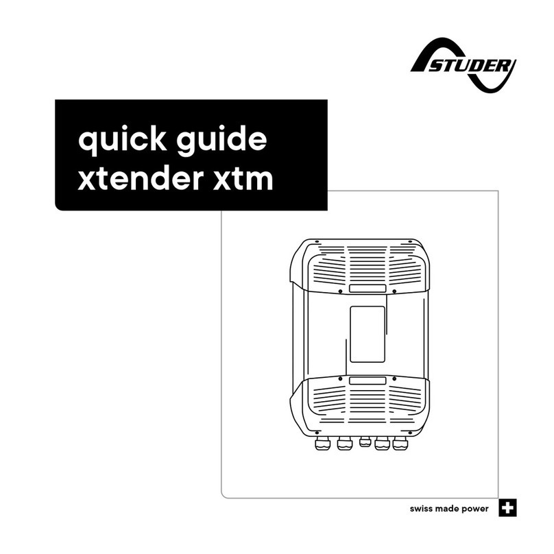
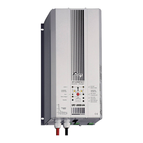
Studer xtender xth User manual

Studer

Studer xtender xth User manual

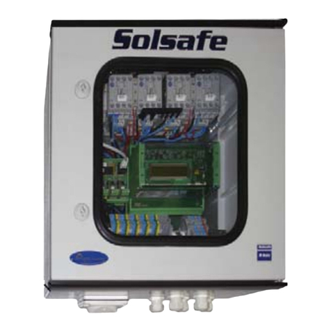
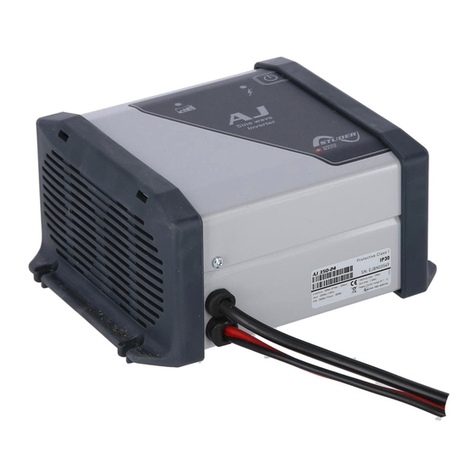
Studer Solsafe concept Installation and operating instructions

Studer

Studer Solsafe concept Installation and operating instructions

Studer VarioTrack VT-40 User manual

Studer

Studer VarioTrack VT-40 User manual

Studer AJ-201 Use and care manual

Studer

Studer AJ-201 Use and care manual

Studer AJ SERIES Use and care manual

Studer

Studer AJ SERIES Use and care manual

Studer AJ 350-24 Use and care manual

Studer

Studer AJ 350-24 Use and care manual

Studer SI Series User guide

Studer

Studer SI Series User guide

Studer AJ 1000 User manual

Studer

Studer AJ 1000 User manual

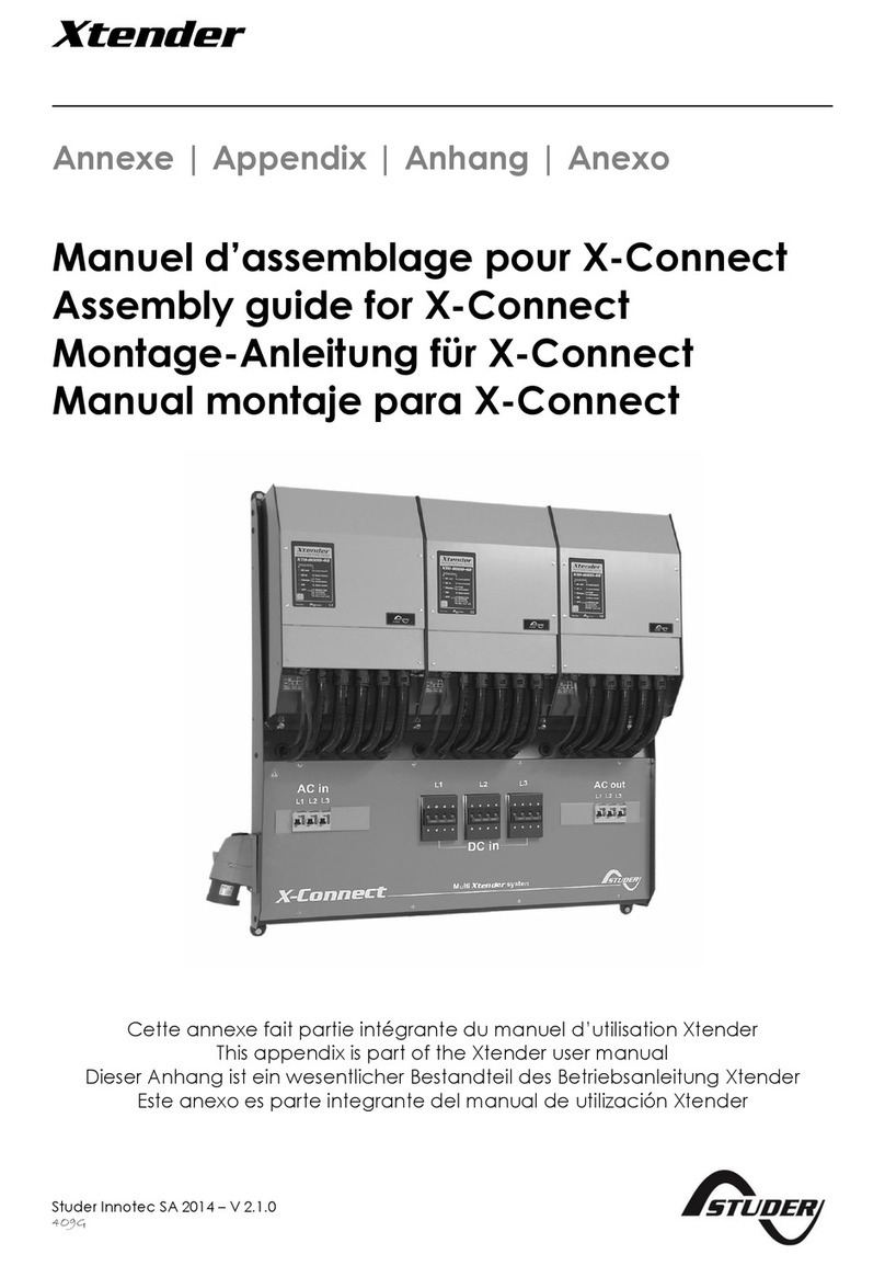
Studer X-Connect User manual

Studer

Studer X-Connect User manual

Studer XP-COMPACT-XPC 1400-12 Use and care manual

Studer

Studer XP-COMPACT-XPC 1400-12 Use and care manual

Studer variotrack User manual

Studer

Studer variotrack User manual

Studer AJ SERIES Use and care manual

Studer

Studer AJ SERIES Use and care manual

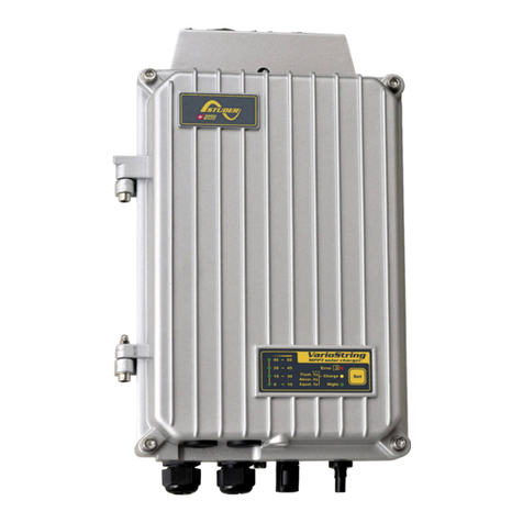
Studer variostring 70 User manual

Studer

Studer variostring 70 User manual

Studer AJ 275-12 Use and care manual

Studer

Studer AJ 275-12 Use and care manual

Studer xtender xts User manual

Studer

Studer xtender xts User manual

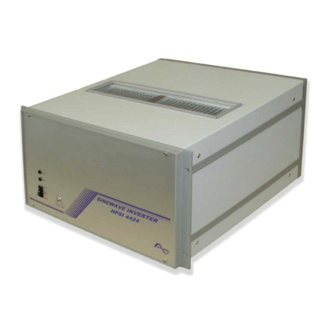
Studer HPSI Series User guide

Studer

Studer HPSI Series User guide

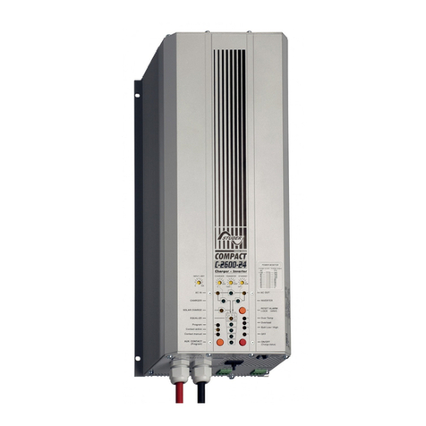
Studer COMPACT C 1600-12 Use and care manual

Studer

Studer COMPACT C 1600-12 Use and care manual

Studer variostring 120 User manual

Studer

Studer variostring 120 User manual

Studer xtender xtm User manual

Studer

Studer xtender xtm User manual
Studer AJ 275 User manual

Studer

Studer AJ 275 User manual

Studer next 3 User manual

Studer

Studer next 3 User manual
Popular Inverter manuals by other brands
Tripp Lite PINV300SW-120 owner's manual

Tripp Lite

Tripp Lite PINV300SW-120 owner's manual

Sofar solar 3.3-12KTL-X user manual

Sofar solar

Sofar solar 3.3-12KTL-X user manual

FRO­NIUS Primo 208 3.8-1 installation instructions

FRO­NIUS

FRO­NIUS Primo 208 3.8-1 installation instructions

MasterPower Omega ESS 5.5KW user manual

MasterPower

MasterPower Omega ESS 5.5KW user manual

XPower 175 PLUS owner's guide

XPower

XPower 175 PLUS owner's guide

FRO­NIUS Primo GEN24 quick start guide

FRO­NIUS

FRO­NIUS Primo GEN24 quick start guide

Sun Power SPR-5200 Installation and operation manual

Sun Power

Sun Power SPR-5200 Installation and operation manual

Tripp Lite PINV2000 owner's manual

Tripp Lite

Tripp Lite PINV2000 owner's manual

FRO­NIUS Symo Advanced Series installation instructions

FRO­NIUS

FRO­NIUS Symo Advanced Series installation instructions

FRO­NIUS Symo Hybrid 3.0 installation instructions

FRO­NIUS

FRO­NIUS Symo Hybrid 3.0 installation instructions

pro user PSI600 operating manual

pro user

pro user PSI600 operating manual

Qcells Q.HOME CORE A5 installation manual

Qcells

Qcells Q.HOME CORE A5 installation manual

Sofar solar 7KTLM-G3 user manual

Sofar solar

Sofar solar 7KTLM-G3 user manual

Tripp Lite PINV750 owner's manual

Tripp Lite

Tripp Lite PINV750 owner's manual

Tripp Lite APSX1250F Specification sheet

Tripp Lite

Tripp Lite APSX1250F Specification sheet

Meanwell TS-1500 Inverter instruction manual

Meanwell

Meanwell TS-1500 Inverter instruction manual

North Light OCL-1169 quick start guide

North Light

North Light OCL-1169 quick start guide

Delta M70A Installation and operation manual

Delta

Delta M70A Installation and operation manual

manuals.online logo
manuals.online logoBrands
  • About & Mission
  • Contact us
  • Privacy Policy
  • Terms and Conditions

Copyright 2025 Manuals.Online. All Rights Reserved.