Alpha IP RTA 61001-N1 User manual

ENGNORSWE DANFINPOLRUS
RTA 61001-N1
132724.1628
Alpha IP

POL RUSFINDAN SWENORENG
2
ENG 6
3
4
DAN
NOR 24
FIN 42
SWE 60
POL 78
RUS 96
1x
1x
2x
2x
2x
1x
2x
2x
M3 x 30 mm
5 mm

ENGNORSWE DANFINPOLRUS
3
~150 cm
~30 cm

POL RUSFINDAN SWENORENG
4
2a 2b 2c
1
B
C
D
E
A

ENGNORSWE DANFINPOLRUS
5
3
4 5 6
20
15
10
25
28
-2K
-1
+1
+2K
0
F
20
15
10
25
28
-2K
-1
+1
+2K
0
G

POL RUSFINDAN SWENORENG
6
ENG
DEU
DEU 6
1 About these instructions 8
1.1 Validity, storage and forwarding of the instructions 8
1.2 Symbols 8
2 Safety 9
2.1 Intended use 9
2.2 Safety notes 9
3 Function 10
4 Device overview 11
4.1 Technical data 12
5 Decommissioning 13
5.1 Teach-in of the device 13
5.1.1 Teach-in to Alpha IP Base Station 13
5.1.2 Teach-in to Alpha IP Access Point 14
5.2 Assembly 15
5.2.1 On-surface wall installation 15
5.2.2 Installation in flush-type box 16
5.2.3 Installation with adhesive strips 17
6 Operation 17
6.1 Set value balance (offset) 17
6.2 Temperature limitation 17
6.2.1 Connection test 18
7 Displays 19
7.1 Status displays 19
7.2 Error indications 10
8 Changing the batteries 21
Contents

ENGNORSWE DANFINPOLRUS
7
ENG
9 Cleaning 21
10 Reset to factory settings 22
11 Decommissioning 23
12 Disposal 23

POL RUSFINDAN SWENORENG
8
ENG
1 About these instructions
1.1 Validity, storage and forwarding of the instructions
1.2 Symbols
The following symbols are used in this manual:
Note: Identifies important or useful information
ÖPreconditions
9Result from an action
• List without fixed order
1., 2. List with fixed order
These instructions apply to the room control unit Analog RTA 61001-N1. These in-
structions include information necessary for commissioning and operation. These
instructions must the read completely and thoroughly before commencing any work
with the device. These instructions must be kept and to be handed over to future
users.
About these instructions
The latest version of these instructions/of Additional Alpha IP System infor-
mation can be found under www.alphaip.de.
System information, functions and operating steps from the instructions for
Alpha IP Access Point (HAP 21001) must be observed.

ENGNORSWE DANFINPOLRUS
9
ENG
2.2 Safety notes
All safety notes in these instructions must be observed in order to avoid accidents
with personal damage or property damage. No liability is assumed for personal and
material damage caused by improper handling or non-observance of the hazard
notes. Such cases render all warranty claims invalid. No liability is assumed for con-
sequential damage!
• Only use the device if it is in flawless state.
• Observe the performance limits of the device and its environmental conditions.
2 Safety
2.1 Intended use
The room control unit Analog RTA 61001-N1 is a component of the Alpha IP System
and serves for
• the installation in residence-related environments,
• the registration of the actual temperature (room temperature),
• the setting of the target temperature (comfort temperature),
• the control of the actual temperature by an activation of the Alpha IP Base sta-
tion for the control of floor heating systems (FAL-x10x1-xx1) or connected Alpha
IP radiator thermostats,
• a wireless communication in the Alpha IP network.
Every other use, modification and conversion is expressively forbidden. Improper use
leads to dangers the manufacturer cannot be held liable for, and to an exclusion of
warranty and liability.
Safety

POL RUSFINDAN SWENORENG
10
ENG
• Only operate this device in a dry and dust-free environment.
• Do not expose the device to humidity, vibration, continuous sunlight or other
types of heat radiation, coldness, or mechanical loads.Ensure that children do
not play with this device or the packaging. Children must be monitored if nec-
essary.
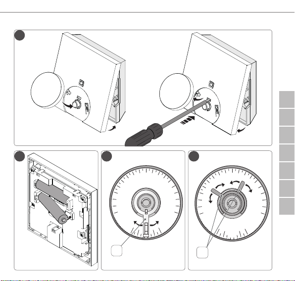
The Alpha IP room control unit Analog RTA 61001-N1 serves for setting the room
temperature according to individual requirements. The room control unit measures
the temperature in the room and transmits these data cyclically to the Alpha IP Base
station FAL-x10x1-xx1 or to connected Alpha IP radiator thermostats. The registered
values allow an exact regulation of the room temperature. The target temperature
can be set manually with the setting wheel (E).
Communication with other components will be performed over the Homematic
(HmIP) radio protocol. The radio transmission is done on a non-exclusive transmis-
sion path; thus, disturbance cannot be completely excluded. Disturbance impacts
can be caused by switching processes, electric motors or electric appliances.
The range within buildings can differ strongly from the range outside (in
open air).
Function
3 Function

ENGNORSWE DANFINPOLRUS
11
ENG
4 Device overview
Device overview (see page 4 fig. 1)
(A) Installation bottom
(B) Room control unit Analog
(C) System button (teach-in button and LED)
(D) SET button
(E) Setting wheel
(F) Setpoint correction limiter
(G) Temperature limiters
Device overview

POL RUSFINDAN SWENORENG
12
ENG
Device overview
Short designation of
device
RTA 61001-N1
Supply voltage 2x 1.5 V LR03/micro/AAA
Power consumption max. 50 mA
Battery service life 2 years (normally)
Protection type IP20
Contamination degree 2
Ambient temperature 0 to 50 °C
Dimensions (W x H x D) 86 x 86 x 20mm / 26mm
Weight 90 g (incl. batteries)
Radio frequency 868.3 MHz/869.525 MHz
Receiver category SRD category 2
Typical radio range 250 m (in open air)
Duty Cycle < 1 % per h/< 10 % per h
Mode of action Type 1
Guidelines 2014/53/EU Telecommunications terminal
equipment
2014/30/EU EMC
2011/65/EU RoHs
4.1 Technical data

ENGNORSWE DANFINPOLRUS
13
ENG
5 Commissioning
5.1 Teach-in of the device
In order be integrated into the Alpha IP System and to communicate with other
devices, the room control unit Analog must be taught-in first. The room control unit
Analog is taught-in directly to the Alpha IP base station, or in conjunction with the
radiator thermostats, to the Alpha IP Access Point. In case of direct teach-in, the
configuration is done on the device itself; in case of teach-in via the Access Point, it
is done via the Alpha IP app.
5.1.1 Teach-in to Alpha IP Base Station
For teach-in, keep a minimum distance of 50 cm between the devices.
The teach-in process can be interrupted by shortly pressing the teach-in key
again. This is confirmed by a short flash in red colour of the device LED.
If no teach-in is performed, the teach-in mode is finished automatically
after 30 seconds.
If the room control unit Analog shall be taught-in to the Alpha IP Base station, the
two devices to be linked must be set to teach-in mode.
Commissioning

POL RUSFINDAN SWENORENG
14
ENG
1. Select the desired channel at the Alpha IP base station (see Alpha IP Base station
instructions).
2. Activate the teach-in mode at the base station by pressing and holding the key.
9The device LED starts to flash in orange.
3. Take off the room control unit Analog from the installation bottom (see page
5, fig. 3).
4. Pull out the insulating strip from the battery compartment, or insert batteries
(see page 5 fig. 4). If batteries have already been inserted, press the system key
(C) for at least 4 seconds in order to activate the teach-in mode.
9The teach-in mode is activated automatically for 3 minutes.
9The device LED flashes in orange.
The LED will light up in green after a successful teach-in process. If the LED
lights up red, repeat the process.
5.1.2 Teach-in to Alpha IP Access Point
For a control via the Alpha IP app, the teach-in must of the RTA 61001-N1 must be
performed via the Access Point (HAP 21001). Teach-in the device as follows:
ÖThe Alpha IP Access Point has been set up via the Alpha IP App (see instructions
HAP 21001).
1. Open the Alpha IP app on the smart phone.
2. Select the menu item Teach-in device.
3. Release the room control unit Analog from the installation bottom (see page 5
fig. 3).
4. Pull out the insulating strip from the battery compartment, or insert batteries (see
page5fig.4)Ifbatterieshavealreadybeeninserted,pressthesystemkey(C)foratleast
4 seconds in order to activate the teach-in mode.
Commissioning

ENGNORSWE DANFINPOLRUS
15
ENG
5. The device is displayed automatically in the Alpha IP app.
6. Enter the last four ciphers of the device number (SGTIN) or scan the supplied QR
code for confirmation. The device number can be found below the QR code or
in the battery compartment.
The LED will light up in green after a successful teach-in process. If the LED
lights up red, repeat the process.
7. Follow the instructions in the app.
5.2 Installation
The place of installation can be selected flexibly due to the battery operation. In-
stallation can be performed with screws, with the supplied adhesive strips, or in a
flush-type box.
5.2.1 On-surface installation
ÖSelect an appropriate installation position.
1. Ensure that the installation position is free from hidden lines.
2. If necessary, release the device from the installation bottom with a suitable
screwdriver (see page 5 fig. 3).
3. Hold the installation bottom to the installation position. Take care to align the
installation bottom correctly (see page 4 fig. 2a/b).
4. Align the installation bottom horizontally.
Commissioning

POL RUSFINDAN SWENORENG
16
ENG
5. Mark two diagonally opposite bore holes using the installation bottom (see page
5 fig. 2a).
If wood walls are present, the screws can be screwed directly into the wood.
Pre-drilling with a 1.5 mm wood drill can facilitate the installation of the
screws.
6. For stone walls, drill the holes at the marked positions with a 5 mm masonry drill.
7. Insert dowels into the bores.
8. Install the installation bottom using the supplied screws (see page 4 fig. 5).
9. Position the room control unit Analog onto the installation bottom and latch it
in (see page 5 fig. 3).
5.2.2 Installation in flush-type box
The fixing holes on the installation bottom can be used for installation on a flush-
type box (see page 4 fig. 2b).
1. If necessary, release the device from the installation bottom with a suitable
screwdriver (see page 5 fig. 4).
2. Align the installation bottom horizontally on the flush-type box.
3. Install the installation bottom with suitable screws (see page 4 fig. 2b).
4. Position the room control unit Analog onto the installation bottom and latch it
into the clips (see page 5 fig. 3).
Commissioning

ENGNORSWE DANFINPOLRUS
17
ENG
5.2.3 Installation with adhesive strips
Depending on the ground, installation can be performed using the supplied dou-
ble-sided adhesive tapes. Installation is possible on different grounds, as e. g. ma-
sonry, furniture, tiles or glass.
1. Select an appropriate installation position.
If the installation is done with adhesive strips, the installation surface must
be smooth, level, undamaged, clean, and free from grease and solvents.
2. Remove the protective foil from one side of the adhesive strip.
3. Fix the adhesive strip on the back side of the installation bottom in the recesses
provided for this (see page 4 fig. 2c).
4. Remove the protective foil from the other side of the adhesive strip.
5. Align the device horizontally to the desired position and press it on.
6 Operation
The target temperature is set manually on a scale from 0 to 5 by turning the setting
wheel (E) to the left or to the right.
6.1 Set value balance (offset)
Since the temperature is measured at the room control unit, it may be warmer or
cooler in another position in the room. The deviation can be corrected via a set value
balance of -2 K to 2 K in 0.5 K increments.
1. Remove setting wheel (E). There is a scale for the balance on the inside of the
setting wheel (E) (see page 5 fig. 5)
2. Insert the set point correction limiter (F) to the desired place in the setting wheel
(E).
Operation

POL RUSFINDAN SWENORENG
18
ENG
6.2 Temperature limitation
The temperature range for the target temperature to be set as a maximum and a
minimum can be limited via the set value elements on the inside of the setting wheel
(E) (see page 5 fig. 6).
1. Remove setting wheel (E). Read the scale for the limitation on the inside of the
setting wheel (E).
2. Insert the target value elements (G) into the setting wheel (E) indicating the
desired range.
6.2.1 Connection test
During this verification the room control unit Analog sends a switching command to
the base station. Depending on the switching status the assigned heating zone has,
it will be switched on or off after receiving the command.
1. Remove setting wheel (E).
2. Press the Set button in order to perform a radio test.
Operation

ENGNORSWE DANFINPOLRUS
19
ENG
Displays
7 Displays
7.1 Status indications
Display Meaning Solution
1 x long illumination in
green
Process confirmed Process with the set-up/
operation.
Short flashing in orange Radio transmis-
sion/transmission
attempt/data trans-
mission
Wait until the transmission
has finished.
1 illumination in orange
and 1 in green (after
inserting batteries)
Test indication After the test indication has
gone out, proceed with the
set-up/operation.
Short flashing in orange
(once every 10 sec.)
Teach-in mode
active
Enter the last four ciphers of
the device serial number for
confirmation.

POL RUSFINDAN SWENORENG
20
ENG
7.2 Error indications
Display Meaning Solution
1 x long illumination
in red
Process failed • Repeat the process.
Short illumination in
orange (after green or
red reception signal)
Batteries dead • Replace batteries.
1 x long illumination
in red
Process failed or
duty cycle limit
reached
• Re-send the command, in
case of exceeding the duty
cycle after one hour at the
latest.
• Check the device for a
defect, e. g. mechanical
blocking.
• Eliminate radio interfer-
ence.
6 x long illumination
in red
Device defective • Observe the indication in
the app.
• Have the device checked
by a specialised dealer.
• Replace the device.
Displays
Other manuals for RTA 61001-N1
2
Table of contents
Languages:
Other Alpha IP Thermostat manuals

Alpha IP
Alpha IP ETRV 61001 User manual

Alpha IP
Alpha IP WTH 61001 User manual

Alpha IP
Alpha IP WTHP 61001 Series User manual

Alpha IP
Alpha IP RTD 61001 Series User manual

Alpha IP
Alpha IP WTH 61001 User manual

Alpha IP
Alpha IP RTD 61001 Series User manual

Alpha IP
Alpha IP Display S User manual

Alpha IP
Alpha IP WRC2 61001 User manual
Popular Thermostat manuals by other brands

Field Controls
Field Controls EvenAir T32 Installation and user manual

Gemtech
Gemtech GT5020 Operation manual

MICRO-AIR
MICRO-AIR EasyTouch 351 operating manual

Honeywell
Honeywell T6 Pro Hydronic user guide

proSmart
proSmart BBoil instruction manual

White Rodgers
White Rodgers 1e+78 installation instructions