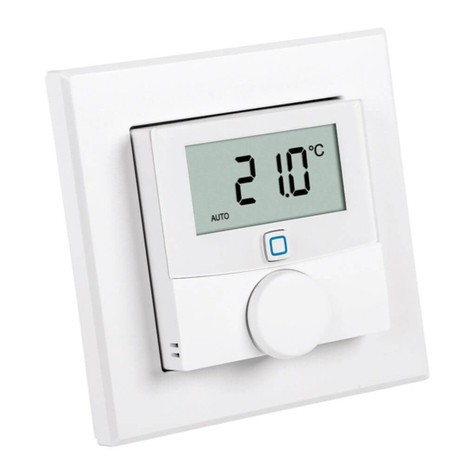
Alpha IP WTH 61001 User manual

ENGNORSWE DANFINPOLRUS
WTH 61001
132853.1628
Alpha IP
Quick Install Guide

POL RUSFINDAN SWENORENG
2
ENG 5
2
3
DAN NOR 14
FIN 23
SWE 32
POL 41
RUS 50
1x
1x
1x
2x
2x
2x
2x
M3 x 30 mm
5 mm

ENGNORSWE DANFINPOLRUS
3
1
AF
C
D
E
B

POL RUSFINDAN SWENORENG
4
R
3
45
S
QP
Q
P
2

ENGNORSWE DANFINPOLRUS
5
ENG
DEU
DEU 5
1 About these instructions 6
1.1 Validity, storage and forwarding of the instructions 6
1.2 Symbols 6
2 Safety 7
2.1 Intended use 7
2.2 Safety notes 7
3 Device overview 8
4 Commissioning 8
4.1 Teach-in of the device 8
4.2 Installation 10
4.2.1 Installation with adhesive strips 10
4.2.2 Installation with screws 11
4.2.3 Installation on flush-type box 12
4.2.4 Installation in multiple combinations 12
5 Decommissioning 13
6 Disposal 13
Contents

POL RUSFINDAN SWENORENG
6
ENG
1 About these instructions
1.1 Validity, storage and forwarding of the instructions
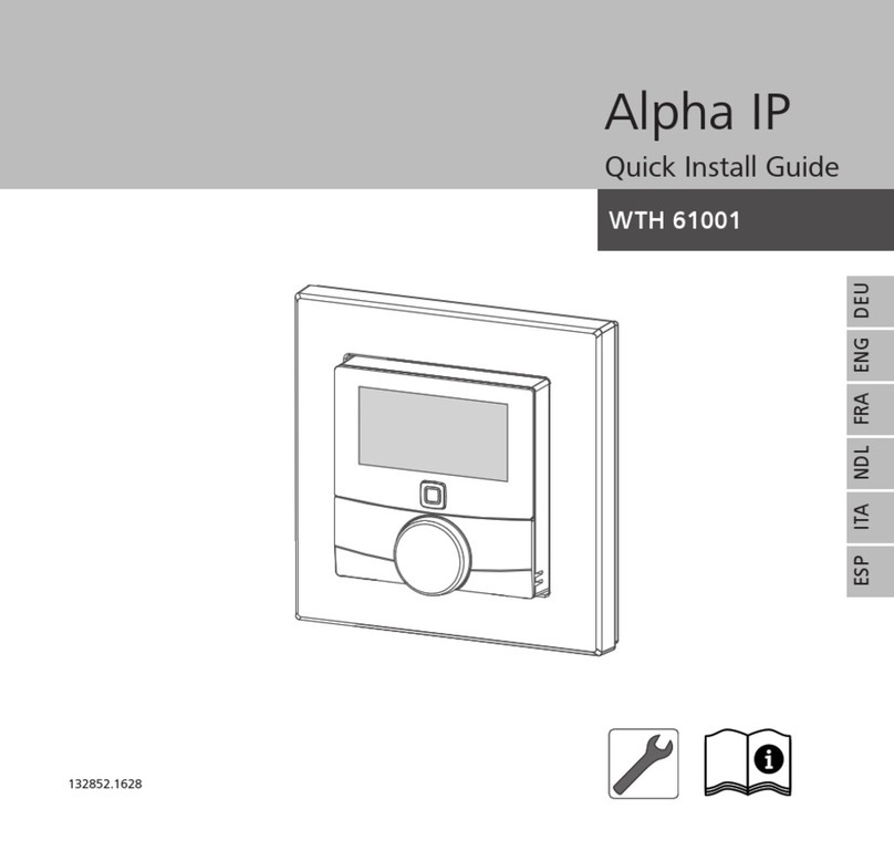
This Quick Install Guide applies to the room control unit Display S (WTH 61001). It
includes information necessary for installation, decommissioning and disposal. The
Quick Install Guide must be kept and to be handed over to future users.
Further information on commissioning, operation and function of the device, as well
additional Alpha IP system information can be found in the operating instructions
on www.alphaip.de.
System information, functions and operating steps from the Alpha IP Access
Point (HAP 2001) instructions must be followed.
1.2 Symbols
The following symbols are used in this manual:
Note:Identifies important or useful information
ÖPreconditions
9Result from an action
• List without fixed order
1., 2. List with fixed order
About these instructions

ENGNORSWE DANFINPOLRUS
7
ENG
Safety
2 Safety
2.1 Intended use
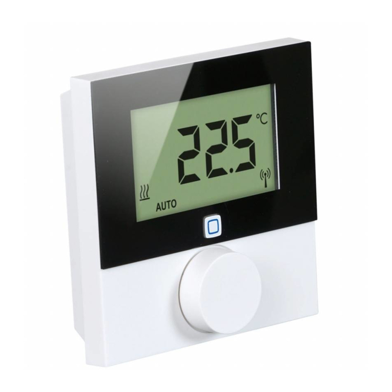
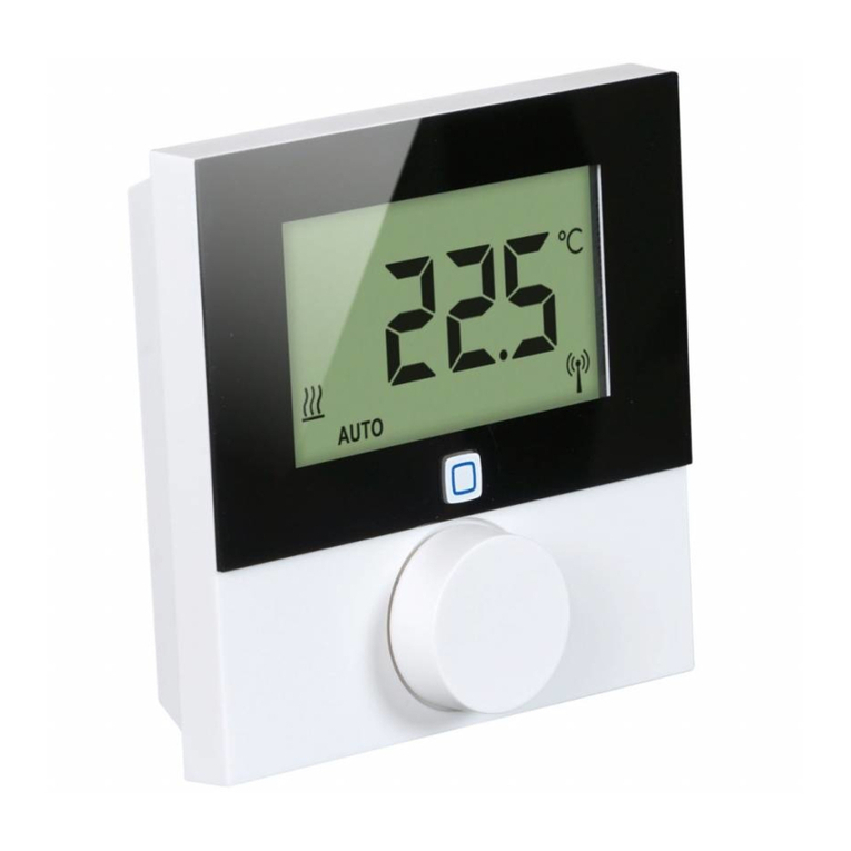
The room control unit Display S (WTH 61001) is a component of the Alpha IP System
and serves
• for installation in environments of residential use,
• for the registration of the actual temperature (room temperature) and the hu-
midity,
• for the setting of the target temperature (comfort temperature),
• for the regulation of the actual temperature by controlling radiator thermostats
and electric heaters with pluggable switch,
• for the wireless communication in the Alpha IP network.
Every other use, modification and conversion is expressively forbidden. Improper
use leads to dangers the manufacturer cannot be held liable for and will exempt
guarantees and liabilities.
2.2 Safety notes
All safety notes in these instructions must be observed in order to avoid accidents
with personal damage or property damage. No liability is assumed for personal
damage and property damage caused by improper use or non-observance of the
danger notes. In such cases any warranty claim is invalid! There is no liability for
consequential damages!

POL RUSFINDAN SWENORENG
8
ENG
• The device may only be opened by an authorised specialist.
• Only use the device if it is in flawless state.
• Observe the performance limits of the device and its environmental conditions.
• Only operate the device in a dry and dust-free environment.
• Do not expose the device to the influence of humidity, vibration, continuous
solar radiation or other types of radiation, coldness or mechanical load.
• Ensure that children do not play with this device or its packaging. Children must
be monitored if necessary.
3 Device overview
(see page 3 fig. 1)
(A) Interchangeable frame
(B) Room control unit Display S
(C) Display
(D) System key (teach-in key and LED)
(E) Setting wheel
(F) Mounting plate
4 Commissioning
4.1 Teach-in of the device
Prior to operating the device, it must be integrated into the Alpha IP system via the
Commissioning

ENGNORSWE DANFINPOLRUS
9
ENG
Commissioning
Access Point (HAP 21001). Teach-in the device as follows:
ÖThe Alpha IP Access Point has been set-up via the Alpha IP app (see manual HAP
21001).
1. Open the Alpha IP app on your smart phone.
2. Select the menu item Teach-in device.
3. Pull the room control unit Display S from the interchangeable frame (see page
4 fig.5).
4. Remove the insulating strip from the battery compartment. The teach-in mode is
automatically activated for three minutes.
Theteach-inmodecanbeactivatedmanuallywiththesystemkey(seeDinfig.1)for
a duration of 3 minutes.
5. The device will be displayed automatically in the Alpha IP app.
6. For confirmation, enter the last four digits of the device number (SGTIN) or scan
the supplied QR code. The device number can be found below the QR code or
in the battery compartment.
The LED will light up in green after a successful teach-in process. The pro-
cess must be repeated if the LED lights up in red.
7. Follow the directions of the app.

POL RUSFINDAN SWENORENG
10
ENG
Commissioning
4.2 Installation
The battery operation allows a free choice of the installation place. The device can
be installed in the supplied interchangeable frame by fixing the mounting plate with
screws or with adhesive tape. An integration into an existing switch series is also
possible.
4.2.1 Installation with adhesive strips
Depending on the surface, installation can be performed with the supplied dou-
ble-sided adhesive tape or with the supplied screws. Installation is possible on differ-
ent surfaces as e. g. masonry, furniture, tiles, or glass.
ÖThe commissioning is finished and the device is readily assembled.
1. Select a suitable installation position.
In case of an installation with adhesive strips the installation surface must be
even, smooth, undamaged, clean, and free from grease and solvents.
2. Remove the protective foil from one side of the adhesive strip.
3. Stick the adhesive tape on the back side of the mounting plate in the recesses
provided for this purpose (see S in fig. 4).
4. Remove the protective foil from the other side of the adhesive strip.
5. Align the device horizontally at the desired position and press it on the surface.
ENGNORSWE DANFINPOLRUS
11
ENG
Commissioning
4.2.2 Installation with screws
ÖSelect a suitable installation position.
1. Ensure that no lines are laid at this position.
2. Remove the mounting plate from the device.
3. Position the mounting plate on the installation place. The arrow on the front of
the mounting plate must show upwards.
4. Align the mounting plate horizontally.
5. Mark two diagonally opposite bores using the mounting plate as a template
(see P in fig. 2).
6. For stone walls, drill the marked holes with a 5 mm masonry drill.
If wooden walls are present, the screws can be directly screwed into the
wood. Pre-drilling with a 1.5 mm wood drill facilitates the screw installation.
7. Insert the dowels into the bores.
8. Install the mounting plate with the supplied screws (see page 4 fig. 3).
9. Install the interchangeable frame onto the mounting plate.
10. Position the device onto the mounting plate and latch it into the clips.

POL RUSFINDAN SWENORENG
12
ENG
Commissioning
4.2.3 Installation on flush-type box
The fixing holes in the mounting plate can be used for installation onto a flush-type
box.
1. Remove the mounting plate from the room control unit Display S.
2. Align the mounting plate horizontally on the flush-type box.
3. Install the mounting plate with the correct screws (see Q in fig. 2).
4. Install the interchangeable frame onto the mounting plate.
5. Position the device onto the mounting plate and latch it into the clips.
4.2.4 Installation in multiple combinations
The device can be used with frames of other manufacturers or be integrated in a
multiple frame. For installation in multiple combinations, install the mounting plate
of the device flushing with the already installed mounting plates/bearer rings and
align it to these. The device will fit into the frames of the following manufacturers:
Manufacturer Frames
Berker S.1, B.1, B.3, B.7 Glass
ELSO Joy
GIRA System 55, Standard 55, E2, E22, Event, Esprit
merten 1-M, Atelier-M, M-Smart, M-Arc, M-Star, M-Plan
JUNG A 500, AS 500, A plus, A creation

ENGNORSWE DANFINPOLRUS
13
ENG
132853.1628
Disposal
5 Decommissioning
1. Pull the room control unit Display S from the frame and the mounting plate (see
page 4 fig.5).
2. Remove the batteries from the back of the device.
3. Uninstall the device and dispose of properly.
6 Disposal
Do not dispose of the device with domestic waste! Electronic devices/prod-
ucts must be disposed of according to the Directive for Waste Electrical and
Electronic Equipment at the local collection points for waste electronic equip-
ment.
This manual is protected by copyright. All rights reserved. It may not be copied, reproduced,
abbreviated or transmitted, neither in whole nor in parts, in any form, neither mechanically nor
electronically, without the previous consent of the manufacturer.
© 2016

POL RUSFINDAN SWENORENG
14
DAN NOR
DA
DAN 5
1 Om denne vejledning 15
1.1 Gyldighed, opbevaring og videregivelse af vejledningen 15
1.2 Symboler 15
2 Sikkerhed 16
2.1 Bestemmelsesmæssig brug 16
2.2 Sikkerhedshenvisninger 16
3 Oversigt over enheden 17
4 Ibrugtagning 17
4,1 Instruktion af enheden 17
4,2 Montering 18
4.2.1 Montering med klæbestrimmel 19
4.2.2 Montering med skruer 19
4.2.3 Montering på et indbygget stik 20
4.2.4 Montering i multikombinationer 21
5 Ud-af-drifttagning 22
6 Bortskaffelse 22
Indhold

ENGNORSWE DANFINPOLRUS
15
DANNOR
1 Om denne vejledning
1.1 Gyldighed, opbevaring og videregivelse af vejledningen
Denne Quick Install Guide gælder for rumtermostaten Display S (WTH 61001). Den
indeholder oplysninger, som er nødvendige til montering, ud-af-brugtagning og
bortskaffelse. Quick Install Guide skal opbevares og videregives til senere brugere.
De videre oplysninger om enhedens ibrugtagning, betjening og funktion samt yder-
ligere Alpha IP systeminformationer kan ses i brugsanvisningen på www.alphaip.de.
Systeminformationer, funktioner og betjeningstrin fra vejledningen til Alpha
IP Access Point (HAP 2001) skal tilgodeses.
1.2 Symboler
Følgende symboler bruges i denne vejledning:
Information: Kendetegner en vigtig og nyttig information
ÖForudsætning
9Resultatet, som fremkommer af en handling
• Optælling uden fast rækkefølge
1., 2. Anvisning med fast rækkefølge
Om denne vejledning

POL RUSFINDAN SWENORENG
16
DAN NOR
Sikkerhed
2 Sikkerhed
2.1 Bestemmelsesmæssig brug
Rumtermostaten Display S (WTH 61001) er en del af Alpha IP systemet og tjener til
• installering i boliglignende omgivelser,
• registrering af den faktiske temperatur (rumtemperatur) og luftfugtighed,
• indstilling af den ønskede temperatur (behagelig temperatur),
• regulering af den faktiske temperatur ved udløsning af radiatortermostater og
el-radiatorer med koblingsstikdåse,
• trådløs kommunikation i Alpha IP netværket.
Enhver anden brug, ændringer og ombygninger er udtrykkeligt forbudte. En ikke
bestemmelsesmæssig brug medfører farer, som producenten ikke hæfter for, samt
til garantiudelukkelse og ansvarsfrihed.
2.2 Sikkerhedshenvisninger
For at undgå ulykker med personskade og materiel skade skal alle sikkerhedsin-
formationer i nærværende vejledning overholdes. Der hæftes ikke for personskade
og materiel skade, som forårsages af ukorrekt brug eller manglende overholdelse
af farehenvisningerne. I sådanne tilfælde bortfalder garantien! Der hæftes ikke for
følgeskader!
• Enheden må kun åbnes af autoriseret fagpersonale.
• Enheden må kun bruges i teknisk upåklagelig tilstand.

ENGNORSWE DANFINPOLRUS
17
DANNOR
• Overhold enhedens effektgrænser og omgivelsesbetingelser.
• Brug kun enheden i tørre samt støvfrie omgivelser.
• Enheden må ikke udsættes for påvirkninger fra fugtighed, vibrationer, konstant
sol- eller anden varmeindstråling, kulde eller mekaniske belastninger.
• Kontroller, at børn ikke leger med produktet eller emballagen. Hold i givet fald
børn under opsyn.
3 Oversigt over enheden
(jf. side 3 fig. 1)
(A) Skifteramme
(B) Rumtermostat Display S
(C) Display
(D) Systemtast (instruktionstast og LED)
(E) Indstillingshjul
(F) Monteringsplade
4 Ibrugtagning
4.1 Instruktion af enheden
Inden enheden kan fungere, skal den integreres i Alpha IP systemet via Access Point
(HAP 21001). Instruér enheden som følger:
ÖAlpha IP Access Point blev indstillet via Alpha IP App (jfr. vejledning HAP 21001).
Ibrugtagning

POL RUSFINDAN SWENORENG
18
DAN NOR
Ibrugtagning
1. Åbn Alpha IP app'en på din smartphone.
2. Vælg menupunktet Instruktion af enheden.
3. Træk rumtermostaten Display S ud af skifterammen (jf. side 4 fig.5).
4. Træk isoleringsstrimlen ud af batterirummet. Instruktionsmodus aktiveres auto-
matisk i 3 minutter.
Instruktionsmodus kan aktiveres manuelt i 3 min. med systemtast (jf. D i fig. 1)
.
5. Enheden vises automatisk i Alpha IP app'en.
6. For at bekræfte skal de sidste fire cifre i enhedens nummer (SGTIN) indtastes
eller den vedlagte QR-koden scannes. Enhedens nummer befinder sig hhv. under
QR-koden og i batterirummet.
Efter en vellykket instruktion lyser LED'en grønt. Lyser LED'en rødt, gentages
processen.
7. Følg instruktionerne i app'en.
4.2 Montering
På grund af batteridriften kan monteringsstedet vælges fleksibelt. Monteringen i
den medleverede skifteramme kan foretages ved fastskruning eller fastklæbning af

ENGNORSWE DANFINPOLRUS
19
DANNOR
Ibrugtagning
monteringspladen. Det er også muligt at integrere i en eksisterende kontaktrække.
4.2.1 Montering med klæbestrimmel
Alt efter undergrunden kan monteringen foretages med de medleverede dobbelt-
sidede klæbestrimler eller med de medleverede skruer. En montering er mulig på
forskellige undergrunde, f.eks. mure, møbler, fliser eller glas.
ÖIbrugtagningen er gennemført, og enheden er sat sammen.
1. Vælg en egnet monteringsposition.
Ved en montering med klæbestrimler, skal monteringsstedets undergrund
være glat, plan, ubeskadiget, ren og fri for fedt og opløsningsmidler.
2. Beskyttelsesfolien på den ene side af klæbestrimlen tages af.
3. Klæbestrimlerne fastgøres på bagsiden af monteringspladen i de dertil beregne-
de fordybninger (jf. S i fig. 4).
4. Beskyttelsesfolien på den anden side af klæbestrimlen tages af.
5. Enheden justeres horisontalt på den ønskede position og trykkes fast.
4.2.2 Montering med skruer
ÖVælg en egnet monteringsposition.
1. Kontroller, at der ikke er ledninger ved denne position.
2. Monteringspladen løsnes fra enheden.

POL RUSFINDAN SWENORENG
20
DAN NOR
Ibrugtagning
1. Monteringspladen holdes mod monteringspositionen. Sørg for, at pilen på forsi-
den af monteringspladen peger opad.
2. Monteringspladen justeres horisontalt.
3. Markér to borehuller diagonalt over for hinanden ved hjælp af monteringspla-
den (jf. P i fig. 2).
4. Ved stenvægge bores de markerede huller med et 5 mm-stenbor.
Ved trævægge kan skruerne indskrues direkte. Det kan gøre indskruningen
af skruerne nemmere, hvis der bores med et 1,5mm træbor.
5. Sæt rawpluggerne ind i boringerne.
6. Moneringspladen monteres ved hjælp af de vedlagte skruer (jf. side 4 fig. 3).
7. Skifterammen sættes på monteringspladen.
8. Enheden sættes på monteringspladen. Lad klemmerne gå i hak.
4.2.3 Montering på et indbygget stik
Fastgørelseshullerne i monteringspladen kan bruges til en montering på et indbyg-
get stik.
1. Monteringspladen løsnes fra enheden rumtermostat Display S.
2. Monteringspladen justeres horisontalt på det indbyggede stik.
Other manuals for WTH 61001
1
Table of contents
Languages:
Other Alpha IP Thermostat manuals

Alpha IP
Alpha IP RTD 61001 Series User manual

Alpha IP
Alpha IP Display S User manual

Alpha IP
Alpha IP WRC2 61001 User manual

Alpha IP
Alpha IP WTH 61001 User manual

Alpha IP
Alpha IP WTHP 61001 Series User manual

Alpha IP
Alpha IP RTD 61001 Series User manual

Alpha IP
Alpha IP RTA 61001-N1 User manual

Alpha IP
Alpha IP ETRV 61001 User manual