Alpha Microsystems AM-314 User manual

RIGHT. FROM THE START
AM-314 Four-Port
Serial I/O Board
Installation Instructions
PDI-00314-00,Rev.A04

1995 Alpha Microsystems
REVISIONS INCORPORATED
REVISION DATE
00 Jan. 1994
01 May 1994
02 Sept. 1994
03 Sept. 1994
04 Dec. 1994
AM-314 Four-Port Serial I/O Board Installation Instructions
To re-order this document, request part number PDI-00314-00.
The information contained in this manual is believed to be accurate and reliable. However, no
responsibility for the accuracy, completeness or use of this information is assumed by Alpha
Microsystems.
This document may contain references to products covered under U.S. Patent Number 4,530,048.
The following are registered trademarks of Alpha Microsystems, Santa Ana, CA 92799:
AMIGOS AMOS Alpha Micro AlphaACCOUNTING
AlphaBASIC AlphaCALC AlphaCOBOL AlphaFORTRAN 77
AlphaLAN AlphaLEDGER AlphaMAIL AlphaMATE
AlphaNET AlphaPASCAL AlphaRJE AlphaWRITE
CASELODE OmniBASIC VER-A-TEL VIDEOTRAX
The following are trademarks of Alpha Microsystems, Santa Ana, CA 92799:
AlphaBASIC PLUS AlphaVUE AM-PC AMTEC
DART ESP MULTI inSight/am
inFront/am
All other copyrights and trademarks are the property of their respective holders.
ALPHA MICROSYSTEMS
2722 S. Fairview Street
P.O. Box 25059
Santa Ana, CA 92799

Page iINSTALLATION INSTRUCTIONS: AM-314 Four Port I/O Board
TABLE OF CONTENTS
1.0 INTRODUCTION . . . . . . . . . . . . . . . . . . . . . . . . . . . . . . . . . . . . . . . . . . . . . . . . 1
2.0 PRODUCT DESCRIPTION . . . . . . . . . . . . . . . . . . . . . . . . . . . . . . . . . . . . . . . . 1
3.0 CONFIGURING YOUR AM-314 BOARDS . . . . . . . . . . . . . . . . . . . . . . . . . . . . . 1
4.0 INSTALLATION OVERVIEW . . . . . . . . . . . . . . . . . . . . . . . . . . . . . . . . . . . . . . . 2
5.0 AM-314 INSTALLATION (ALL AM-1600 COMPUTERS) . . . . . . . . . . . . . . . . . . 2
5.1 Installing the I/O Cables . . . . . . . . . . . . . . . . . . . . . . . . . . . . . . . . . . . . . 4
5.2 Modifying the System Initialization Command File . . . . . . . . . . . . . . . . . 6
5.3 Finishing the Installation . . . . . . . . . . . . . . . . . . . . . . . . . . . . . . . . . . . . . 10
6.0 AM-314 INSTALLATION (EAGLE SERIES COMPUTERS) . . . . . . . . . . . . . . . . 11
6.1 Eagle 300 AM-319(-00) I/O Expansion Slots . . . . . . . . . . . . . . . . . . . . . 14
6.2 Eagle 200 AM-319(-10) I/O Expansion Slots . . . . . . . . . . . . . . . . . . . . . 15
6.3 Eagle 100 AM-137 I/O Expansion Slot . . . . . . . . . . . . . . . . . . . . . . . . . . 16
6.4 Installing the AM-314 Board . . . . . . . . . . . . . . . . . . . . . . . . . . . . . . . . . . 17
6.5 Eagle 300 Rear Panel I/O Configuration . . . . . . . . . . . . . . . . . . . . . . . . 17
6.6 Eagle 200 Rear Panel I/O Configuration . . . . . . . . . . . . . . . . . . . . . . . . 19
6.7 Eagle 100 Rear Panel I/O Configuration . . . . . . . . . . . . . . . . . . . . . . . . 21
6.8 Installing AM-314 DB9 Connectors on the Rear Panel . . . . . . . . . . . . . 23
6.9 System Initialization Command File (Eagle 300 and 200) . . . . . . . . . . . 24
6.10 System Initialization Command File (Eagle 100) . . . . . . . . . . . . . . . . . 27
6.11 Finishing the Installation . . . . . . . . . . . . . . . . . . . . . . . . . . . . . . . . . . . . 30
7.0 DB-9 CONNECTOR SIGNALS FOR RS-232 AND RS-422 . . . . . . . . . . . . . . . . 30
8.0 TERMINAL CABLES . . . . . . . . . . . . . . . . . . . . . . . . . . . . . . . . . . . . . . . . . . . . . 31
8.1 AM-65 Terminal and RS-422 Cabling . . . . . . . . . . . . . . . . . . . . . . . . . . . 32
8.2 Workstation . . . . . . . . . . . . . . . . . . . . . . . . . . . . . . . . . . . . . . . . . . . . . . . 32
9.0 PRINTER CABLES . . . . . . . . . . . . . . . . . . . . . . . . . . . . . . . . . . . . . . . . . . . . . . 34
PDI-00314-00, Rev. A04

Page 1INSTALLATION INSTRUCTIONS: AM-314 Four Port I/O Board
1.0INTRODUCTION
The instructions in this document describe the installation of AM-314 four-port serial I/O
boards into AM-1600 (both desktop and deskside models), as well as Eagle 100, 200,
and 300 computers. The information is written for the experienced Alpha Micro Service
Technician, so if you do not feel comfortable performing the hardware and software
procedures discussed below, please contact your Alpha Micro Dealer or the Alpha Micro
Technical Support Group for help.
2.0PRODUCT DESCRIPTION
The AM-314 board supports four asynchronous serial I/O ports. AM-314 serial ports can
be individually configured for either RS232 or RS422 protocols. Each AM-314 board is
linked to the rear panel of your computer using a 40-pin cable with four female DB9
connectors at one end and a standard 40-pin connector at the other. The AM-1600’s
AM-135 board has four slots designed for serial I/O expansion. Eagle 300 computers
have also have four I/O expansion slots; Eagle 200 computers have two I/O expansion
slots; and Eagle 100 computers have one I/O expansion slot.
Eagle computers also support the AM-318 eight-port serial I/O board. Special
instructions on mixing AM-314 and AM-318 boards in Eagle computers can be found in
the
AM-318 Eight-Port Serial I/O Board Installation Instructions.
3.0CONFIGURING YOUR AM-314 BOARDS
There are no address jumpers on the AM-314 board. In fact, the only jumpers on the
board are the RS422/232 jumpers. The jumpers at location W0 control the RS422/232
selection for the first port; the W1 jumpers control the second port; the W2 jumpers
control the third port; the W3 jumpers control the fourth port. All boards are shipped
configured for RS232 as shown in the illustration below:
U2
RN2
PIN-1
MC1083
J1
U1
DWB-00314-00, REV. X
ALPHA MICROSYSTEMS
RN1
422 232 422 232 422 232 422 232
W0
W1
W2W3
AM-314 Four-Port Serial I/O Board
PDI-00314-00, Rev. A04

Page 2 INSTALLATION INSTRUCTIONS: AM-314 Four Port I/O Board
4.0INSTALLATION OVERVIEW
The installation instructions are identical for AM-1600 desktop and deskside computers;
however, there are some significant differences in the procedure for installing an
AM-314 board into an Eagle computer. Because of the differences, the AM-1600
(desktop and deskside) AM-314 installation instructions and the Eagle AM-314
installation instructions will be split into two sections. Section 5.X will include the
AM-314 installation information for AM-1600 computers and Section 6.X will include the
AM-314 installation information for Eagle computers.
5.0AM-314 INSTALLATION (ALL AM-1600 COMPUTERS)
The first step in the installation process is to remove the computer’s top cover.
Instructions for removing the top cover from the AM-1600 desktop model are located in
the
AM-1600 Computer Owner’s Manual
. For the deskside AM-1600, instructions for
removing your computer’s top cover are located in the
AM-1600 Deskside Computer
Service Manual.
With the AC power cord unplugged and the top cover removed, the components inside
your computer are vulnerable to damage caused by static discharge. Your body and
clothing are capable of storing an electrical charge that can damage or destroy
unprotected electronic components. Prior to handling any computer hardware, make
sure your work area is properly protected against static discharge. There are a number
of commercially available static protection devices designed specifically to protect your
equipment from harmful static discharge.
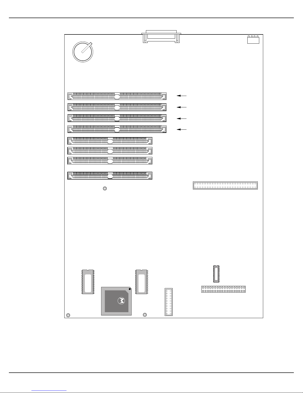
Once the top cover is removed, you will be able to access your computer’s main circuit
board, which is called the AM-135. The AM-135 board has four expansion slots
designed for AM-314 I/O boards.
The AM-135 board illustration, located on the following page, shows the four serial I/O
expansion slots: J17, J16, J15, and J14. As indicated in the illustration, the first I/O
board installs in J17, the second in J16, the third in J15, and the fourth in J14.
PDI-00314-00, Rev. A04

Page 3INSTALLATION INSTRUCTIONS: AM-314 Four Port I/O Board
AM-135 BOARD
AM-135 BOARD
J10
J11
J12
J13
J14
J15
J16
J17
J9
BATTERY
SW1
J18
J19
MC1084
MC68020
135-01
135-00
U116U121
U133
U104
135-15
1STAM-314 INSTALLS AT THIS LOCATION
2ND AM-314 INSTALLS AT THIS LOCATION
3RD AM-314 INSTALLS AT THIS LOCATION
4THAM-314 INSTALLS AT THIS LOCATION
AM-135 Board I/O Expansion Slots
PDI-00314-00, Rev. A04

Page 4 INSTALLATION INSTRUCTIONS: AM-314 Four Port I/O Board
The AM-135’s I/O expansion slots are very similiar to the type of slots memory SIMM
modules plug into. The AM-314 board should be inserted into the appropriate slot with
the component side of the AM-314 board facing your computer’s rear panel. The
AM-314 must be inserted into the expansion slot at a slight angle and after you feel the
board settle into the slot, you rotate it into an upright position. When the AM-314 is
properly positioned, the metal retainer clips at each end of the expansion slot will click
into position, locking the board in place.
5.1Installing the I/O Cables
The cable that links your AM-314 board to the rear panel of your computer has four
female DB9 connectors at one end and a standard 40-pin connector at the other. Plug
one 40-pin I/O cable into each of the AM-314 boards. The 40-pin connector on the
AM-314 board has an embossed arrow showing the pin-1 location. Make sure the red
stripe on the I/O cable aligns with the embossed arrow on the connector.
The rear panel of your computer has 16 DB9 cutouts labeled 0 through 15. The
illustration on the following page shows the DB9 connector orientation for both desktop
and deskside AM-1600 computers:
PDI-00314-00, Rev. A04

Page 5INSTALLATION INSTRUCTIONS: AM-314 Four Port I/O Board
MC1085
08
19
210
311
412
513
614
715
PARALLEL 0
IN
OUT
SCSI
SCSI
0
1
2
3
4
5
6
7
9111315
8101214
AM-1600 DESKTOP SERIAL I/O CONFIGURATION
AM-1600 DESKSIDE SERIAL I/O
CONFIGURATION
AM-1600 Rear Panel Serial I/O Configuration
The AM-314 board plugged into connector J17 attaches to the rear panel at locations 0,
1, 2, and 3. The AM-314 board plugged into connector J16 attaches to the rear panel at
locations 4, 5, 6, and 7. The AM-314 board plugged into connector J15 attaches to the
rear panel at locations 8, 9, 10, and 11. The AM-314 board plugged into connector J14
attaches to the rear panel at locations 12, 13, 14, and 15.
PDI-00314-00, Rev. A04

Page 6 INSTALLATION INSTRUCTIONS: AM-314 Four Port I/O Board
One end of the AM-314 40-pin I/O cable splits of into four separate cables, each with its
own DB9 connector. Notice how the cable leading to each of the DB9 connectors is
marked:
(P0, 4, 8, 12)
(P1, 5, 9, 13)
(P2, 6, 10, 14)
(P3, 7, 11, 15)
The first number following the letter "P" applies to the AM-314 board installed in
connector J17; the second number following the P applies to the AM-314 board installed
in connector J16; the third number following the P applies to the AM-314 board installed
in connector J15; the last number following the P applies to the AM-314 board installed
in connector J14.
Attach the DB9 connectors to the rear panel of your computer, using the 3/16" hex-nuts
included in the mounting kit.
Re-install the AM-1600M top cover.
5.2Modifying the System Initialization Command File
In order to use a serial port, it needs to be defined in your system initialization command
file. This file, which is located in the SYS: account, is called AMOSL.INI. Within this file,
serial ports are defined using an octal (base 8) numbering system. The octal number
used corresponds directly to what slot on the AM-135 a particular I/O board is plugged
into. The following table shows the AM-314 octal port numbers for each of the four I/O
expansion slots on the AM-135 board:
AM-135 I/O EXPANSION
SLOT OCTAL PORT NUMBERING
FOR AM-314 BOARDS
J17
J16
J15
J14
0 -3
4 - 7
10 - 13
14 - 17
MC1086
AM-135 / AM-314 Octal Port Numbering Scheme
PDI-00314-00, Rev. A04

Page 7INSTALLATION INSTRUCTIONS: AM-314 Four Port I/O Board
To illustrate how AM-314 serial ports are defined in the AMOSL.INI file, we’ll construct a
sample system initialization command file based on the installation of four AM-314
boards.
It’s never a good idea to directly modify your AMOSL.INI file; always create a test file;
type:
LOG SYS:
RETURN
COPY TEST.INI=AMOSL.INI
RETURN
Several areas in the TEST.INI file need to be modified:
1.You need to make sure the total number of jobs assigned to the JOBS statement
is increased by the number of new serial ports being added to the computer. The
example configuration has four AM-314 boards, which is a total of 16 serial ports.
For our example configuration, we will set the JOBS statement to 22, which will
allow for all the serial ports, the AM-1600’s one on-board parallel port, and a
couple of extras to support spawned jobs.
2.You must also add some additional JOBALC statements. JOBALC allocates a
name to each defined job. In our TEST.INI file, we’ll use names like JOB1, JOB2,
etc. However, you could just as easily use TOM, DICK, HARRY, etc.
3.Roadrunner enhanced AM-1600 computers require a healthy quantity of queue
blocks. When you add new serial ports, you need to increase your queue block
allocation. Use the following queue block formula to determine how many queue
blocks you require.
NEW QUEUE BLOCK REQUIREMENT = OLD QUEUE BLOCKS + (13 x THE NUMBER OF JOBS)
For example, if the QUEUE statement in your system initialization command file is
currently set to 200 and the JOBS statement is set to 22, the resulting formula
would look like this:
NEW QUEUE BLOCK REQUIREMENT = 200 + (13 x 22)
For our example, the QUEUE statement should be changed to 486 to
accommodate our new queue block requirements.
4.You will also need to add a TRMDEF statement to your TEST.INI file for each new
port. The TRMDEF statement is where the octal port number is assigned. The
basic elements that make up a TRMDEF statement are shown below:
PDI-00314-00, Rev. A04

Page 8 INSTALLATION INSTRUCTIONS: AM-314 Four Port I/O Board
TRMDEF TERM7,AM135=10:19200,ALPHA,100,100,100
TRMDEF command
Assigned name
Serial port driver name
Octal port number
BAUD rate
Terminal driver name
In-width buffer size
In-buffer size
Out-buffer size
MC1087
TRMDEF Command Statement
5.Finally, you will add SETJOB statements that attach the JOBALC name to the
TRMDEF name, assign memory to the job, and log the job on.
An Example of our TEST.INI file with all the support statements for the four AM-314
boards is shown on the next page.
PDI-00314-00, Rev. A04

Page 9INSTALLATION INSTRUCTIONS: AM-314 Four Port I/O Board
:T
JOBS 22
JOBALC JOB1,JOB2,JOB3,JOB4,JOB5,JOB6,JOB7,JOB8,JOB9,JOB10
JOBALC JOB11,JOB12,JOB13,JOB14,JOB15,JOB16
;
QUEUE 486
;
TRMDEF TERM1,AM135=0:19200,ALPHA,100,100,100
TRMDEF TERM2,AM135=1:19200,ALPHA,100,100,100
TRMDEF TERM3,AM135=2:19200,ALPHA,100,100,100
TRMDEF TERM4,AM135=3:19200,ALPHA,100,100,100
TRMDEF TERM5,AM135=4:19200,ALPHA,100,100,100
TRMDEF TERM6,AM135=5:19200,ALPHA,100,100,100
TRMDEF TERM7,AM135=6:19200,ALPHA,100,100,100
TRMDEF TERM8,AM135=7:19200,ALPHA,100,100,100
TRMDEF TERM9,AM135=10:19200,ALPHA,100,100,100
TRMDEF TERM10,AM135=11:19200,ALPHA,100,100,100
TRMDEF TERM11,AM135=12:19200,ALPHA,100,100,100
TRMDEF TERM12,AM135=13:19200,ALPHA,100,100,100
TRMDEF TERM13,AM135=14:19200,ALPHA,100,100,100
TRMDEF TERM14,AM135=15:19200,ALPHA,100,100,100
TRMDEF TERM15,AM135=16:19200,ALPHA,100,100,100
TRMDEF TERM16,AM135=17:19200,ALPHA,100,100,100
;
DEVTBL DSK1,DSK2
DEVTBL TRM,RES,MEM
DEVTBL /VLP0
;
BITMAP DSK
SYSTEM TRM.DVR
SYSTEM VLP.DVR[1,6]
SYSTEM
SETJOB JOB2,TERM2,500K,LOGIN
SETJOB JOB3,TERM3,500K,LOGIN
SETJOB JOB4,TERM4,500K,LOGIN
SETJOB JOB5,TERM5,500K,LOGIN
SETJOB JOB6,TERM6,500K,LOGIN
SETJOB JOB7,TERM7,500K,LOGIN
SETJOB JOB8,TERM8,500K,LOGIN
SETJOB JOB9,TERM9,500K,LOGIN
SETJOB JOB10,TERM10,500K,LOGIN
SETJOB JOB11,TERM11,500K,LOGIN
SETJOB JOB12,TERM12,500K,LOGIN
SETJOB JOB13,TERM13,500K,LOGIN
SETJOB JOB14,TERM14,500K,LOGIN
SETJOB JOB15,TERM15,500K,LOGIN
SETJOB JOB16,TERM16,500K,LOGIN
;
;
MOUNT DSK1:
MOUNT DSK2:
;
MEMORY 0
Update JOBS and JOBALC statements
QUEUE block allocation increased
TRMDEF statements for 1st AM-314
TRMDEF statements for 2nd AM-314
TRMDEF statements for 3rd AM-314
TRMDEF statements for 4th AM-314
SETJOB statements for all serial ports
Sample TEST.INI File
When installing an AM-314 serial I/O board into an AM-135 board, make sure you use
AM135 as the serial port driver in your TRMDEF statements.
PDI-00314-00, Rev. A04

Page 10 INSTALLATION INSTRUCTIONS: AM-314 Four Port I/O Board
5.3Finishing the Installation
Once you have created a TEST.INI file that is applicable to your configuration, you need
to verify it has been correctly modified. You do this by using the MONTST command:
LOG OPR:
RETURN
MONTST AMOSL,TEST.INI
RETURN
Watch closely as the system initialization command file is executed; make sure no
errors are displayed on your terminal screen. If an error does occur, take another look at
your TEST.INI file; double check your octal port numbers and other statements you
added to support the serial ports.
After you are certain your TEST.INI file is working correctly, execute the following
command:
COPY AMOSL.INI=TEST.INI
RETURN
PDI-00314-00, Rev. A04

Page 11INSTALLATION INSTRUCTIONS: AM-314 Four Port I/O Board
6.0AM-314 INSTALLATION (EAGLE SERIES COMPUTERS)
The first step in the installation process is to remove your computer’s top cover.
Instructions for removing the top cover are located in the
Eagle Computer Service
Manual
.
With the AC power cord unplugged and the top cover removed, the components inside
your computer are vulnerable to damage caused by static discharge. Your body and
clothing are capable of storing an electrical charge that can damage or destroy
unprotected electronic components. Prior to handling any computer hardware, make
sure your work area is properly protected against static discharge. There are a number
of commercially available static protection devices designed specifically to protect your
equipment from harmful static discharge.
After your computer’s top cover has been removed, you need to gain access to the main
electronics board. If you have an Eagle 200 or 300 computer, access to your main
electronics board may be blocked if your Roadrunner board is mounted vertically, as
shown in the next two illustrations. If this true for your application, you will need to
remove the Roadrunner board and its mounting bracket in order to install your I/O board
or boards. Instructions for doing this are shown in the illustrations.
Many Eagle 200 and 300 computers have their Roadrunner boards mounted on the
bottom of the chassis in the horizontal position, which does not block access to the main
electronics board. Also, Eagle 100 computers do not use a separate Roadrunner board
and access to the main electronics board is not a problem.
PDI-00314-00, Rev. A04

Page 12 INSTALLATION INSTRUCTIONS: AM-314 Four Port I/O Board
DWF-20754-00
Your Roadrunner 030 or 040 board is mounted
on the DWF-20754-00 bracket shown above.
To access the board, you need to remove
these four phillips-head screws. Once the
screws are removed, the mounting bracket
and board assembly can be folded down onto
your work surface.
MC1055
Roadrunner Mounting Bracket
PDI-00314-00, Rev. A04

Page 13INSTALLATION INSTRUCTIONS: AM-314 Four Port I/O Board
ROADRUNNER 030 OR 040
BOARD
With the Roadrunner and its mounting bracket
folded down out of the way, you will be able to
access the main electronics board.
MC1162
MAIN BOARD
Locating the Main Electronics Board
PDI-00314-00, Rev. A04

Page 14 INSTALLATION INSTRUCTIONS: AM-314 Four Port I/O Board
6.1Eagle 300 AM-319(-00) I/O Expansion Slots
The AM-319 board illustration shows the four serial I/O expansion slots: J8, J9, J10, and
J11. As indicated in the illustration, the first I/O board installs in J8, the second in J9, the
third in J10, and the fourth in J11.
J10
J9
J8
J14
J2 J1
J3
BATTERY
J5 J6
J11
J7
W5
J15
J12
J13
W3
W1
W6
W9
W10
MC1062
1ST I/O BOARD INSTALLS IN SLOT J8
2ND I/O BOARD INSTALLS IN SLOT J9
3RD I/O BOARD INSTALLS IN SLOT J10
4TH I/O BOARD INSTALLS IN SLOT J11
U6
AM-319 I/O Expansion Slots
PDI-00314-00, Rev. A04

Page 15INSTALLATION INSTRUCTIONS: AM-314 Four Port I/O Board
6.2Eagle 200 AM-319(-10) I/O Expansion Slots
The AM-319(-10) board illustration shows the two serial I/O expansion slots: J6 and J7.
As indicated in the illustration, the first I/O board installs in J7 and the second in J6.
J6
J1
J3 J5
J8 J9
W9
J10
W6
W5
MC1160
J7
BATTERY
J2
J4
W8
W7
w1
w2
w3
w4
1ST I/O BOARD INSTALLS IN SLOT J7
2ND I/O BOARD INSTALLSIN SLOT J6
U2
U3
AM-319(-10) I/O Expansion Slots
PDI-00314-00, Rev. A04

Page 16 INSTALLATION INSTRUCTIONS: AM-314 Four Port I/O Board
6.3Eagle 100 AM-137 I/O Expansion Slot
The AM-137 board illustration shows the one serial I/O expansion slot at location J6.
BATTERY
J1
W1
J5J4
J2 J3
ALPHA MICROSYSTEMS
W4
W5
J8 J9
J6
J7
W10
J11
W11
J10
W13
W14
W7
POWER
RUN
DISK
W8
W12
W9
W6
030
FOUR ON-BOARD (4-7)
RS232 SERIAL PORTS
FOUR ON-BOARD (0-3)
RS232 SERIAL PORTS
OSCILLATOR JUMPERS
DO NOT REMOVE
1ST (AND ONLY) I/O BOARD INSTALLS IN SLOT J6
SSD
W3
W2
AM-137
MC1161
U28 U29
U14 U15
AM-137 I/O Expansion Slot
The AM-137 board has one I/O expansion slot that will support one AM-314 board. In
addition, the AM-137 board has eight standard RS232 on-board serial ports, which are
attached to the rear panel using exactly the same type of cable assembly used by
AM-314 boards.
The Eagle 100’s eight on-board serial ports can take advantage of a feature called
Super I/O. Super I/O handles character output in a much more efficient manner than
any other previously released AMOS serial port driver. This greatly reduces the load on
the CPU and makes more CPU cycles available for other tasks. More information about
Super I/O is located in your
Eagle Series Computer Owner’s Manual
and in the
AM-318
Eight-Port Serial I/O Installation Instructions
.
PDI-00314-00, Rev. A04

Page 17INSTALLATION INSTRUCTIONS: AM-314 Four Port I/O Board
6.4Installing the AM-314 Board
The Eagle’s I/O expansion slots are very similiar to the type of slots memory SIMM
modules plug into. The AM-314 board should be inserted into the appropriate slot with
the component side of the AM-314 board facing your computer’s rear panel. The
AM-314 must be inserted into the expansion slot at a slight angle and after you feel the
board settle into the slot, you rotate it into an upright position. When the AM-314 is
properly positioned, the metal retainer clips at each end of the expansion slot will click
into position, locking the board in place.
Very little force is required to install an AM-314 board. If you’re having problems
installing the board in the expansion slot, stop and take a moment to examine both the
AM-314 and the slot. Make sure you are installing the AM-314 with the component side
of the board facing your computer’s rear panel.
6.5Eagle 300 Rear Panel I/O Configuration
The next step in the installation process is to install the I/O cables that link your AM-314
boards to the rear panel of your computer.
The next illustration shows how rear panel serial I/O connector positions correspond to
where a particular I/O board is plugged into the AM-319 board (i.e., J8, J9, J10, and
J11):
If you are mixing AM-314 and AM-318 serial I/O boards in your Eagle computer, please
see the
AM-318 Eight-Port Serial I/O Board Installation Instructions
for more information
on installing I/O cables.
PDI-00314-00, Rev. A04
Table of contents
Other Alpha Microsystems Motherboard manuals