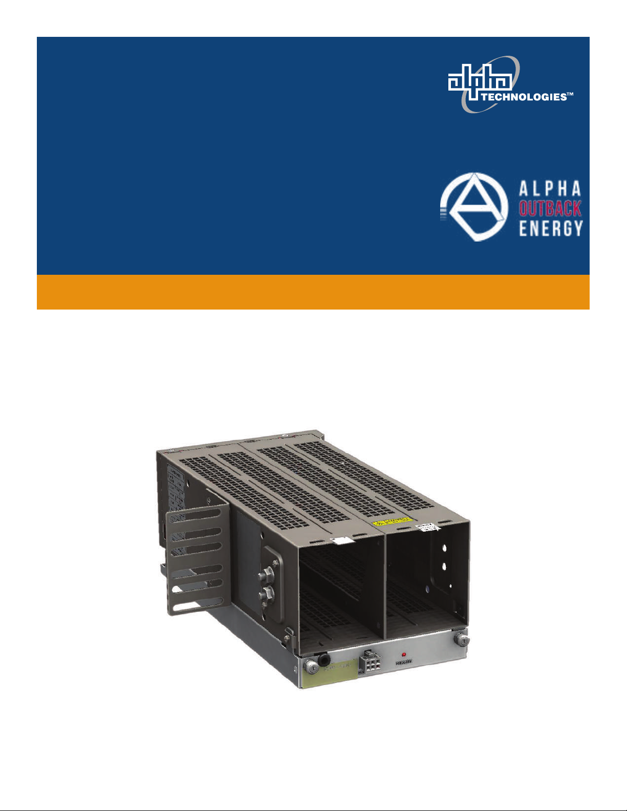
Alpha Technologies ALPHA OUTBACK ENERGY Cordex HP LPS36 Compact User manual

Your Power Solutions Partner
Cordex HP LPS36 Compact
Installation Manual
Part # 0300189-J1
Effective: 07/2020


NOTE:
Photographs contained in this manual are for illustrative purposes only. These photo-
graphs may not match your installation.
NOTE:
Operator is cautioned to review the drawings and illustrations contained in this manual
before proceeding. If there are questions regarding the safe operation of this powering
system, contact Alpha and Outback Energy GmbH or your nearest AOE representative.
NOTE:
AOE shall not be held liable for any damage or injury involving its enclosures, power
supplies, generators, batteries, or other hardware if used or operated in any manner or
subject to any condition inconsistent with its intended purpose, or if installed or oper-
ated in an unapproved manner, or improperly maintained.
Alpha and Outback Energy GmbH
Tel: +49 9122 79889 0
Mail: [email protected]
Copyright
Copyright © 2015 Alpha Technologies Ltd. All rights reserved. Alpha is a registered trademark of Alpha Technolo-
gies.
No part of this documentation shall be reproduced, stored in a retrieval system, translated, transcribed, or transmit-
ted in any form or by any means manual, electric, electronic, electromechanical, chemical, optical, or otherwise
without prior explicit written permission from Alpha Technologies.
This document, the software it describes, and the information and know-how they contain constitute the proprietary,
confidential and valuable trade secret information of Alpha Technologies, and may not be used for any unauthorized
purpose, or disclosed toothers without the prior written permission ofAlpha Technologies.
The material contained in this document is for information only and is subject to change without notice. While
reasonable efforts have been made in the preparation of this document to assure its accuracy, Alpha Technologies
assumes no liability resulting from errors or omissions in this document, or from the use of the information contained
herein. Alpha Technologies reserves the right to make changes in the product design without reservation and with-
out notification to its users.
To download the full LPS36 manual go to the Alpha website.
NOTE:


Table of Contents
Safety �����������������������������������������������������������������������������������������������������������������������������������4
2. Product Overview
3 Product Specifications.......................
4 Site Evaluation and Pre-Installation

1� Safety
SAVE THESE INSTRUCTIONS: This manual contains important safety instructions that must be followed
during the installation, servicing, and maintenance of the product. Keep it in a safe place. Review the drawings
and illustrations contained in this manual before proceeding. If there are any questions regarding the safe
installation or operation of this product, contact Alpha Technologies or the nearest Alpha representative.
1.1 Safety Symbols
To reduce the risk of injury or death, and to ensure the continued safe operation of this product, the following
symbols have been placed throughout this manual. Where these symbols appear, use extra care and attention.
NOTE:
A NOTE provides additional information to help complete a specific task or procedure.
Notes are designated with a checkmark, the word NOTE, and a rule beneath which the
information appears
CAUTION!
CAUTION indicates safety information intended to PREVENT DAMAGE to material or
equipment. Cautions are designated with a yellow warning triangle, the word CAUTION,
and a rule beneath which the information appears.
WARNING!
WARNING presents safety information to PREVENT INJURY OR DEATH to personnel.
Warnings are indicated by a shock hazard icon, the word WARNING, and a rule beneath
which the information appears.
HOT!
The use of HOT presents safety information to PREVENT BURNS to the technician or
user.
1.2 General Warning and Cautions
WARNING!
This system is designed to be installed in a restricted access location that is
inaccessible to the general public.
1.3 Mechanical Safety
CAUTION!
Do not disassemble the product – call our qualified service centers for servicing.
Incorrect reassembling may result in a risk of electrical shock or fire.
Do not operate the product if it has received a sharp blow, it has been dropped, or
otherwise damaged in any way – return it to a qualified service center for repair.

1�4 Electrical Safety
Before working with any live battery or power system, follow these precautions:
a. Remove all metallic jewelry, such as watches, rings, metal rimmed glasses, or necklaces.
b. Wear safety glasses with side shields at all times during the installation.
c. Use OSHA approved insulated hand tools. Do not rest tools on top of batteries.
WARNING!
Potentially harmful voltages are present within the power system. Always assume that
an electrical connection or conductor is energized. Check the circuit with a voltmeter
with respect to the grounded portion of the enclosure (both AC and DC) before perform-
ing any installation or removal procedure.
• Do not work alone under hazardous conditions.
• A licensed electrician is required to install permanently wired equipment. Hazardous voltages are present at
the input of power systems. Ensure that the utility power is disconnected and locked out before performing
any installation or removal procedure.
• Ensure that no liquids or wet clothes come into contact with internal components.
• Hazardous electrically live parts inside this unit are energized from the batteries even when the AC input
power is disconnected.
• The enclosure which contains the DC or AC power system along with customer installed radios must remain
locked at all times, except when authorized service personnel are present.
• Always assume electrical connections or conductors are live. Turn off all circuit breakers and double-check
with a voltmeter before performing installation or maintenance.
• Place a warning label on the utility panel to warn emergency personnel that a reserve battery source is pres-
ent which will power the loads in a power outage condition or if the AC disconnect breaker is turned off.
• At high ambient temperature conditions, the internal temperature can be hot so use caution when touching
the equipment.
WARNING!
The DC input to the modules (and the converter system) – though not dangerous in volt-
age – has a high short circuit current capacity that may cause severe burns and electri-
cal arcing.
The DC output is a potentially dangerous voltage. Do not touch the output connections
when under power. Ensure that power has been removed from the outputs before work-
ing on them.

2� Product Overview
• High efficiency >92% for increased OPEX savings and reduced carbon footprint
• High temperature tolerance for installation in harsh OSP cabinet environment
• Industry leading power density enabling 16 channels in a compact 2RUx6” footprint
• High reliability convection-cooled design with optional fan tray
The LPS36 Compact is a modular DC to DC up-converter system designed for distributed power communications
applications using +/- 190Vdc (RFT-V circuit) over existing copper network. Using switched mode technology, the
LPS36 quad output converter module provides outstanding efficiency in a compact design. Applications include
powering sealed DSLAM’s, Distribution Point Units (DPU) as well as Optical Network Terminals in Fiber to the Home
Networks.
The LPS36 packs maximum power into minimum space, but doesn’t compromise on features. The shelf provides up
to 16 line powering channels in the compact 2RUx6”x12” form. Standard system features include major and minor
alarms for monitoring, connectorized cable output and one side mounting. This product is particularly suitable for
remote OSP power cabinets where free rack space is tight or non-existent. With a six inch width and a single side
bracket, it can be easily mounted to the side of a rack support post without using up valuable rack space.
Alpha’s LPS36 Compact modular DC to DC converter systems incorporate a full range of standard features,
including current limiting and individual ground fault interrupt for each circuit. Particular emphasis is placed on
recognizing a fault condition and shutting down the circuit as quickly as possible to ensure the highest level of
personnel safety. Compliance with GR-1089-CORE - Class A2 provides the ability to work on the equipment while
powered, which significantly reduces the administrative and labeling requirements and overheads for the high
voltage wiring.
Product part numbers
Product Part number

3� Product Specifications
Electrical
Mechanical
6” shelf - 4 modules (P/N 0300189-001)
Environmental
Efficiency:

Performance/ Features
Agency Compliance

4� Site Evaluation and Pre-Installation
4�1 Pre-Installation Requirements
4�1�1 Effective Capacitance
The effective capacitance of each output of the LPS36 is 2.7 microfarads maximum between the output connections
to the telecommunications network and 0.5 microfarads between each output connection to the telecommunica-
tions network and earth ground.
• At the time of installation, carry out a system assessment to ensure that the effective capacitance of the total
system, including the capacitance of the LPS36 output system, does not exceed 11 µF (Line to Earth) and 40µF
(Line to Line).
4�1� 2 RFT-V Circuits
• At the time of installation, ensure that the voltage rating of the wiring of the telecommunication network is ad-
equate for the normal RFT circuit voltage (+/-200Vdc), together with superimposed transients.
• Ensure that the circuits to be connected together are all RFT-V circuits.
4�1�3 Primary Protection
The LPS36 Compact has built-in second level surge protection in compliance with the GR-1089 requirement. Pri-
mary protection must be in place at the customer site.
The LPS36 Compact includes secondary surge protection. External primary surge protection devices are necessary
to optimally protect the RFT-V circuits from lightning surge and maintain safety certification to UL/CSA 60950-21.
Each channel (pair) must be properly protected by the upstream system using a 5-pin protector to a level corre-
sponding to a Bourns 2410 Series. For example: 2410-33-G-MSP-S provides the part in a red color. This protector
should be UL 497 listed and rated for 300-400 Volts voltage breakdown range.
4�1�4 Transient Response
The LPS36 output has been designed to provide protection against typical input and output voltage surges. For
example, in the event of any single isolated 75 Vdc/9.5ms overvoltage transient being applied between the input
power terminals, the LPS36 Compact will continue to operate properly, and will not be damaged or degraded in
performance.
However, the RFT-V output may exhibit a momentary voltage over/under-shoot by as much as 25% of the nominal
output voltage, depending on the characteristics of the equipment being connected as a load. The down-con-
verter connected at the remote end is expected to tolerate this dynamic line voltage swing.
In the event of lightning surges and AC power faults, the RFT-V output ports of the LPS36 channel will experience
voltage surges of up to a few thousand volts, but the equipment will not be damaged, and will continue to operate
without manual intervention after normally expected electrical stresses and transients (i.e. first-level surges), and
will remain safe under less frequently encountered severe stresses and transients (i.e. second-level surges).
For critical application that requires a more robust system such that any momentary interruption on the remote
end is not acceptable (as caused by input or output transients described above), Alpha recommends using the
AlphaCap 665 Short Duration Backup Supply Module (p/n 013-015-20) in conjunction with Alpha CSM46.
For more information on this subject, please refer to Telcordia Technologies Generic Requirements document for
Electromagnetic Compatibility (EMC) and Electrical Safety – Generic Criteria for Network Telecommunications
Equipment (GR-1089-CORE).

5� LPS36 Compact System Installation
• Remove all metallic jewelry; e.g., watches, rings, metal rimmed glasses, necklaces.
• Wear safety glasses with side shields (and prescription lenses if necessary) at all times during installation.
Use insulated metallic tools.
The installer should follow all applicable local rules and regulations for electrical and battery installations; e.g., CSA,
UL, CEC, NEC, OSHA, and local fire codes.
This chapter is provided for qualified personnel to install an LPS36 Compact system.
5.1 General Instructions
This chapter provides cabling details and notes on cable sizing for DC applications.
Connections to the converter system must comply with all the local codes and ordinances.
5.2 Safety Precautions
WARNING!
The DC input to the modules (and the converter system) – though not dangerous in
voltage – has a high short circuit current capacity that may cause severe burns and
electrical arcing.
The DC output is a potentially dangerous voltage. Do not touch the output connections
when under power. Ensure that power has been removed from the outputs before
working on them.
WARNING!
The intra-building ports (Ethernet, CAN, alarm relays) of the equipment or
subassembly are suitable for connection to intra-building or unexposed wiring or
cabling only. The intra-building port(s) of the equipment or subassembly MUST NOT be
metallically connected to interfaces that connect to the OSP or its wiring. These
interfaces are designed for use as intra-building interfaces only (Type 2 or Type 4
ports) and require isolation from the exposed OSP cabling. The addition of Primary
Protectors is not sufficient protection in order to connect these interfaces metallically
to OSP wiring.
Before working with any live power system, take the following precautions:

5�3 Tools Required
Various insulated tools are essential for product installation. The following list is a guide:
• Phillips head screwdriver, #2 (tip size 3/16")
• Slot head screwdriver (blade size 1/8")
• Digital voltmeter equipped with test leads
• Cutters, crimpers, and wire strippers 0.25 to 10mm2(#24 to #6 AWG)
CAUTION!
The LPS36 Compact is suitable for connection to the central office.
The LPS36 Compact must be grounded via a copper ground conductor.
Before making connections all bare grounding connection points to the LPS36 Compact must be cleaned
and coated with an anti-oxidant solution.
Before making connections all surfaces on the LPS36 Compact that are un-plated must be brought to a
bright finish and treated with an anti-oxidant solution.
To ensure electrical continuity, all non-conductive surface coating on the LPS36 Compact should be
removed from all threads and all connection points.
The LPS36 Compact utilizes a 2-hole compression lug with a #8AWG wire.

5�3�1 Rack Mounting
Use the bracket provided to mount LPS36 Compact shelf to a structural component, typically one side of an
equipment rack or a frame inside an outside plant enclosure. The bracket can be assembled to the left or right
side of the shelf depending on the installation. When a fan tray is used, the shelf can be in any orientation de-
pending on the space available. When a fan tray is not used, the LPS36 Compact can only be orientated in the
normal, upright position as shown in Figure 2. In both situations, pay attention to air flow requirements around the
shelf.


5�3�2 Fan Tray Installation
Fan tray installation should be done before the shelf is mounted to the rack.
1. Assemble the fan holding cradle to the rear bottom of the shelf, secure with two screws.
2. Attach two fan mount brackets to the front, left and right side of the shelf and secure with screws on both
sides.
3. Cut the cable tie holding the fan connector to free the fan wire.
4. Remove the wire grommet from the fan tray and wrap it on fan wire about 1-1/2" from the connector.
5. Slide the back side of the fan tray to the cradle at and angle.
6. Insert the wire grommet back to the slot with fan wire, and then move the fan tray front into position so that the
two thumb screws can be engaged and tightened.
7. Plug the fan connector to the fan tray.


5�3�3 Thermal Management
To facilitate adequate air flow to cool the modules, leave minimum 1/2 RU space at both air in-take and air exhaust of
the LPS36 Compact. This applies to all mounting orientations. The three modes for thermal management are:
1. Natural convection cooling.
2. Forced air cooling without a fan tray.
3. Forced air cooling with a fan tray.
CAUTION!
CAUTION: For natural convection cooling the only orientation that can be used is the
following one pictured in Figure 8, Thermal Management, Natural Convection.
Table of contents
Other Alpha Technologies Industrial Equipment manuals

Alpha Technologies
Alpha Technologies 030-706-J0 User manual

Alpha Technologies
Alpha Technologies Tri Power X31 HE User manual

Alpha Technologies
Alpha Technologies ALPHA OUTBACK ENERGY Cordex HP LPS04 User manual

Alpha Technologies
Alpha Technologies Cordex 24-3.1kW User manual

Alpha Technologies
Alpha Technologies ALPHA OUTBACK ENERGY Cordex 48-1kW User manual