Alpha Technologies Tri Power X31 HE User manual

Fragen? Jetzt Kontakt aufnehmen.
Headquarter Germany
Hansastrasse 8
D–91126 Schwabach
Germany
Die Firma Alpha Technologies GmbH behält sich das Recht vor, Änderungen an den hier enthaltenen Produkten und Informa-
tionen vorzunehmen, ohne Vorankündigung. Copyright © 2020 Alpha und Outback Energy GmbH. Alle Rechte vorbehalten.
Kontakt
T: +49 9122 79889 0
F: +49 9122 79889 21
Ofces
Eastern Europe | Middle East
Belgium | France
Spain | Africa
Tri Power X31 HE – 10 to 20 kVA
USER MANUAL

- 2 -
INTRODUCTION
Thank you for choosing this product.
Our company is specialized in the design, development and production of uninterruptible power supplies (UPS).
The TRIPOWER X31 HE described in this manual is a high-quality, meticulously-designed product, built to guarantee the best
performance.
This manual contains detailed instructions on how to use and install the product.
For information on how to use your equipment to its full potential, this manual should be kept close at hand beside the
TRIPOWER X31 HE and READ BEFORE STARTING TO WORK ON IT.
© Copying all or any part of this manual is strictly prohibited unless due authorization has been granted by the manufacturers.
In order to improve the product, the manufacturers reserve the right to make changes to it at any time and with no notice.

- 3 -
CONTENTS
OVERVIEW 5
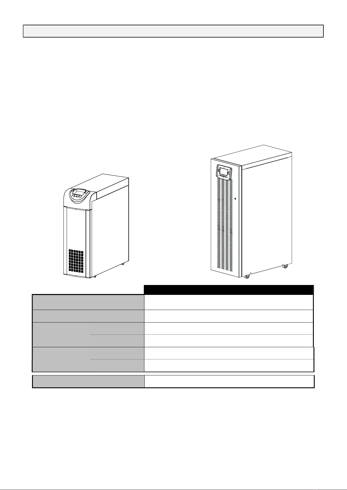
OPTIONAL SMALL SIZE TRIPOWER X31 HE VIEWS 6
STANDARD TRIPOWER X31 HE VIEWS 7
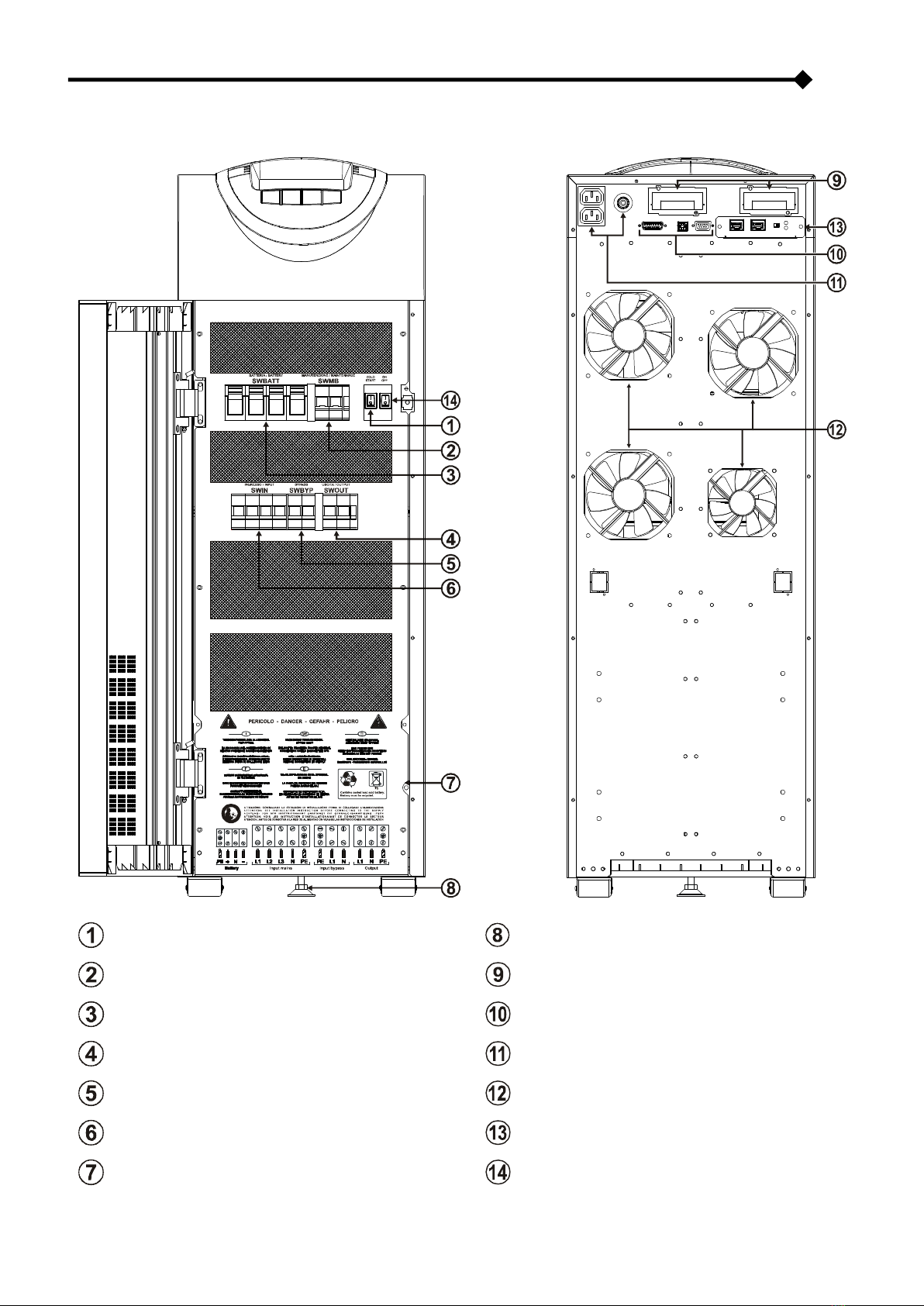
VIEW OF THE TRIPOWER X31 HE CONNECTIONS 8
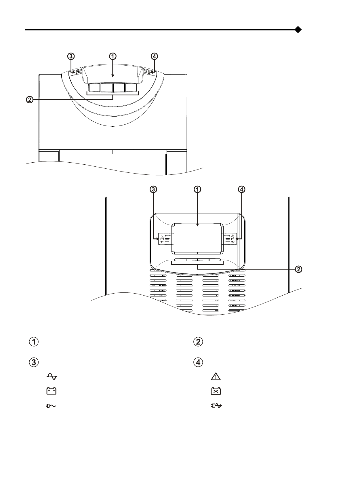
VIEW OF THE CONTROL PANEL 9
BATTERY BOX (OPTIONAL) 10
SEPARATE BYPASS INPUT (OPTIONAL) 11
INTERNAL TRANSFORMER 11
ADDITIONAL INTERNAL BATTERY CHARGERS 11
INSTALLATION 12
STORING THE TRIPOWER X31 HE AND THE BATTERY BOX 12
PREPARING FOR INSTALLATION 12
PRELIMINARY INFORMATION 12
ELECTROMAGNETIC COMPATIBILITY 13
INSTALLATION ENVIRONMENT 13
REMOVING THE TRIPOWER X31 HE AND THE BATTERY BOX FROM THE PALLET 14
PRELIMINARY CHECK OF CONTENTS 16
INSTALLING THE TRIPOWER X31 HE AND THE BATTERY BOX 16
STEPS TO BE TAKEN TO GAIN ACCESS TO THE TERMINALS OF THE TRIPOWER X31 HE / BATTERY BOX 16
ELECTRICAL CONNECTIONS 17
WIRING DIAGRAMS FOR CONNECTING TO THE ELECTRICAL SYSTEM 17
INTERNAL PROTECTIVE DEVICES OF THE TRIPOWER X31 HE 20
EXTERNAL PROTECTIVE DEVICES 21
CROSS SECTION OF THE CABLES 22
CONNECTIONS 22
CONNECTIONS OF THE MODEL WITH SEPARATE BYPASS 23
CONNECTION OF TRIPOWER X31 HE SINGLE-PHASE INPUT 23
R.E.P.O. 24
EXTERNAL SYNC 24
CONNECTING THE REMOTE MAINTENANCE BYPASS 25
CONNECTING THE BATTERY BOX TO THE TRIPOWER X31 HE 27
MULTIPLE EXPANSIONS 28
SETTING THE RATED BATTERY CAPACITY – SOFTWARE CONFIGURATION 28
EXTERNAL TEMPERATURE PROBE 29

- 4 -
REMOTE PANEL (OPTIONAL) 29
USE 30
DESCRIPTION 30
PRELIMINARY OPERATIONS 31
POWERING ON FOR THE FIRST TIME 32
POWERING ON FROM THE MAINS 33
POWERING ON FROM THE BATTERY 33
POWERING OFF THE TRIPOWER X31 HE 33
GRAPHIC DISPLAY 34
DISPLAY MENUS 35
OPERATING MODES 36
MAINTENANCE BYPASS (SWMB) 36
REDUNDANT AUXILIARY POWER SUPPLY FOR AUTOMATIC BYPASS 37
PROGRAMMABLE AUXILIARY SOCKET (POWER SHARE) 37
POWER WALK-IN 37
REDUCING THE LOAD (TO 200V AND 208V) 37
CONFIGURING THE TRIPOWER X31 HE 38
COMMUNICATION PORTS 40
RS232 AND USB CONNECTORS 40
COMMUNICATION SLOTS 40
AS400 PORT 41
BUZZER 42
SOFTWARE 43
MONITORING AND CONTROL SOFTWARE 43
CONFIGURATION SOFTWARE 43
TROUBLESHOOTING GUIDE 44
STATUS / ALARM CODES 48
TECHNICAL DATA 52

- 5 -
OVERVIEW
The new three-phase/single-phase TRIPOWER X31 HE 10 – 15 – 20 kVA series (VFI-SS-111 type) have been designed using
the latest technology available today so as to guarantee users maximum performance. The use of the new control PCBs based
on multiprocessor architecture (DSP + P inside) together with high frequency IGBT technology offers excellent performance both
in the input stage (absorbed current harmonic distortion ≤ 3%) and in output (output voltage distortion ≤ 1%).
Thanks to these and many other features plus the easy-to-use design, this new series represents a new reference standard for
single-phase output TRIPOWER X31 HE systems.
Depending on user requirements, there are two different versions available:
Optional Small Size
The Optional Small Size version stands out by its
compact size and new, modern design. These features
make it suitable for any environment.
Standard
The Standard version, offers longer autonomy than
the Optional Small Size version, thanks to the
possibility to double the number of batteries inside the
cabinet.
10 kVA 15 kVA 20 kVA
Nominal power 10000 VA
8000 W
15000 VA
12000 W
20000 VA
16000 W
Output power factor 0.8 0.8 0.8
Weight (with
batteries)
Optional Small
Size 180 Kg 190 Kg 195 Kg
Standard 305 Kg 315 Kg 320 Kg
W x D x H
Optional Small
Size 320 x 840 x 930 mm
Standard 440 x 850 x 1320 mm
Accessories Battery cabinets – Communication boards – Remote mimic panel

- 6 -
OPTIONAL SMALL SIZE TRIPOWER X31 HE VIEWS
Battery start button (COLD START)
Brake rod
Manual bypass switch Slots for accessory communication cards
Battery fuse holder isolator Communication ports (AS400, USB, RS232)
Output switch
Powershare sockets (10A max. total on the two
sockets) and relative protection
Separate bypass switch (optional) Ventilation fans
Input switch Parallel PCB (optional)
Terminal cover panel 1/0 main power switch

- 7 -
STANDARD TRIPOWER X31 HE VIEWS
Battery start button (COLD START)
Brake rod
Manual bypass switch Slots for accessory communication cards
Battery fuse holder isolator Communication ports (AS400, USB, RS232)
Output switch
Powershare sockets (10A max. total on the two
sockets) and relative protection
Separate bypass switch (optional) Ventilation fans
Input switch Parallel PCB (optional)
Terminal cover panel Remote Emergency Power Off (R.E.P.O.)

- 8 -
VIEW OF THE TRIPOWER X31 HE CONNECTIONS
Connection for the R.E.P.O command (Remote Emergency Power Off)
(see previous page for the Standard version)
Power connections: BATTERY, INPUT, SEPARATE BYPASS (optional), OUTPUT
Connection for remote maintenance bypass command
Connection for external Battery Box temperature probe
Connection for external synchronization signal
Slot for power relay board
Area for the single-phase short-circuit bar

- 9 -
VIEW OF THE CONTROL PANEL
Graphic display Function keys *
Left-hand LEDs area: Right-hand LEDs area:
Mains power LED Stand-by / alarm LED
Battery power LED Battery low LED
Load on bypass LED ECO mode LED
* The function of each key is indicated at the bottom of the display and varies according to the menu used.

- 10 -
BATTERY BOX (OPTIONAL)
THE BATTERY BOX IS AN OPTIONAL ACCESSORY. THIS TRIPOWER X31 HE RANGE HAS BATTERY BOX VERSIONS
OF THE SAME SIZE AND MATCHING STYLE.
The Battery Box contains batteries that increase the operating time of the UPS during prolonged black-outs. The number of
batteries contained in it will vary according to the type of TRIPOWER X31 HE to which the Battery Box is to be installed. The
utmost attention must be paid to ensure that the battery voltage of the Battery Box corresponds to that supported by the UPS.
Optional Small Size Standard
Additional Battery Boxes may be connected in a chain to obtain the desired autonomy time during a power failure.
This series of Battery Box contains two separate strings of batteries, one with a positive voltage and the other with a negative
voltage with respect to the neutral terminal (N).
The basic diagram for the Battery Box is shown here below.
Optional Small Size
BB480
-
A5
BB480
-
M5
Rated voltage 240 + 240 Vdc 240 + 240 Vdc
Weight 150Kg 270Kg
W x D x H 320 x 840 x 930 mm
Standard
BB480X
-
M5
BB480X
-
M7
BB480X
-
M3
BB480X
-
M6
Rated voltage 240 + 240 Vdc 240 + 240 Vdc 240 + 240 Vdc 240 + 240 Vdc
Weight 300 Kg 390 Kg 395 Kg 400 Kg
W x D x H 400 x 815 x 1320 mm

- 11 -
SEPARATE BYPASS INPUT (OPTIONAL)
THE DI (OPTIONAL) VERSION OF THE TRIPOWER X31 HE SERIES HAS SEPARATE BYPASS AND INPUT LINES.
The TRIPOWER X31 HE series with separate Bypass ensures a separate connection between the input and bypass lines.
The TRIPOWER X31 HE output is synchronised with the bypass line so as to safeguard against incorrect voltage changeovers in
the alternate phases, in the event of automatic bypass or closing of the maintenance switch (SWMB).
INTERNAL TRANSFORMER
THE OT (OPTIONAL) VERSION OF THE TRIPOWER X31 HE SERIES DIFFERS FROM THE OPTIONAL SMALL SIZE
VERSION IN THAT IT USES AN ISOLATION TRANSFORMER INSTEAD OF THE BATTERIES.
This series of TRIPOWER X31 HE uses an isolation transformer connected to the UPS output terminals.
NOTE: A separate bypass line is supplied on this UPS version.
The transformer is connected to the TRIPOWER X31 HE output terminals, so the values displayed are those of the
quantities measured upstream of the transformer.
The presence of the transformer inside the UPS modifies the system neutral arrangements.
The installation of a remote maintenance bypass parallel to the UPS is incompatible with inclusion of the
transformer. In any event, if the remote maintenance bypass is inserted, make sure, at the time the remote bypass
switch is closed, that the UPS is isolated from the system by opening the input and/or output switches.
ADDITIONAL INTERNAL BATTERY CHARGERS
THE AC (OPTIONAL) VERSION OF THE TRIPOWER X31 HE SERIES DIFFERS FROM THE OPTIONAL SMALL SIZE
VERSION IN THAT SOME ADDITIONAL BATTERY CHARGERS ARE USED INSTEAD OF THE BATTERIES.
This series of TRIPOWER X31 HE must be used together with an external Battery Box and is suitable for applications requiring
long back-up times.
NOTE: A separate bypass line is supplied on this UPS version.
The additional internal battery charger cards are powered directly on mains power and have pseudo-sinusoidal wave form
absorption.
If the input switch is closed but the I/O switch is open (UPS switched off) the battery chargers operate independently.
Open the input switch (SWIN) to totally shutdown the UPS and the additional battery chargers.
AC Version 10 kVA 15 kVA 20 kVA
Nominal voltage 240 + 240 Vdc
Current in addition to that supplied
by the internal battery charger 6A@240Vdc

- 12 -
INSTALLATION
ALL THE OPERATIONS DESCRIBED IN THIS SECTION ARE TO BE PERFORMED EXCLUSIVELY BY
QUALIFIED STAFF.
The company declines all liability for damage caused by incorrect connections or operations not described
in this manual.
STORING THE TRIPOWER X31 HE AND THE BATTERY BOX
The storage room must respect the following conditions:
Temperature: 0°÷40°C (32°÷104°F)
Relative humidity: max. 95%
PREPARING FOR INSTALLATION
PRELIMINARY INFORMATION
TRIPOWER X31 HE models 10 kVA 15 kVA 20 kVA
Rated power 10000 VA 15000 VA 20000 VA
Working temperature 0 ÷ 40 °C
Max. relative humidity during operation 90 % (non-condensing)
Max. height of installation
1000 m at rated power
(-1% Power for every 100 m above 1000 m)
max 4000 m
W x D x H
Optional Small
Size 320 x 840 x 930 mm
Standard 440 x 850 x 1320 mm
Weight (w/ batteries)
Optional Small
Size 180 Kg 190 Kg 195 Kg
Standard 305 Kg 315 Kg 320 Kg
Power dissipated at rated resistive load
(pf=0.8) and with battery as buffer *
0.56 kW
480 kcal/h
1910 B.T.U./h
0.765 kW
660 kcal/h
2610 B.T.U./h
1.02 kW
880 kcal/h
3480 B.T.U./h
Power dissipated at rated distortion load
(pf=0.7) and with battery charged *
0.49 kW
420 kcal/h
1660 B.T.U./h
0.67 kW
580 kcal/h
2290 B.T.U./h
0.90 kW
775 kcal/h
3070 B.T.U./h
Flow rate of fans for removing heat from
installation room ** 300 mc/h 410 mc/h 545 mc/h
Current leak to earth *** < 7 mA
Isolation protection IP20
Cable input From bottom / on rear
* 3.97 B.T.U./h = 1 kcal/h
** The following formula can be used to calculate the fan capacity: Q [mc/h] = 3.1 x Pdiss [kcal/h] / (ta - te) [°C]
Pdiss is the dissipated power of all the installed apparatus at the installation premises expressed in kcal/h.
ta= environmental temperature, te= external temperature. To account for leaks, increase the value obtained by 10%.
The table shows an example of the fan capacity with (ta - te)=5°C and with nominal resistive load (pf=0.8).
(N.B.: The formula applies if ta>te; otherwise an air conditioner should be installed).
*** The dispersion current of the load is added to the dispersion current of the UPS on the earth protection conductor.

- 13 -
ELECTROMAGNETIC COMPATIBILITY
This TRIPOWER X31 HE product conforms to the current electromagnetic compatibility (EMC) regulations (C2 class). It may
cause radio interference in the home environment. The user may have to adopt supplementary measures.
This product is for professional use in industrial and commercial environments. Connections to USB and RS232 connectors must
be made with the cables provided, or at least with shielded cables less than 3 metres long.
INSTALLATION ENVIRONMENT
When choosing the site in which to install the TRIPOWER X31 HE and the Battery Box, the following points should be taken into
consideration:
Avoid dusty environments
Check that the floor is level and capable of withstanding the weight of the TRIPOWER X31 HE and the Battery Box
Avoid cramped environments that could impede the normal maintenance activities
The relative humidity should not exceed 90%, non-condensing
Check that the ambient temperature, with the TRIPOWER X31 HE running, remains between 0 and 40°C
The UPS may be operated with an ambient temperature of between 0 and 40°C. The recommended
working temperature for the UPS and the batteries is between 20 and 25°C. In fact, if the battery has an
average life of 5 years with a working temperature of 20°C, the life is halved if the working temperature is
increased to 30°C.
Avoid installing the equipment in places exposed to the direct sunlight or hot air
To keep the temperature of the installation room within the range indicated above, there must be a system for eliminating the
dissipated heat (the TRIPOWER X31 HE kW / kcal/h / B.T.U./h dissipation values are shown in the table on the previous page).
The methods that may be used are:
Natural ventilation
Forced ventilation, recommended if the outside temperature is less (e.g. 20°C) than the temperature at which the
TRIPOWER X31 HE or Battery Box is to be operated (e.g. 25°C)
Air-conditioning system, recommended if the outside temperature is higher (e.g. 30°C) than the temperature at which the
TRIPOWER X31 HE or Battery Box is to be operated (e.g. 25°C)

- 14 -
REMOVING THE TRIPOWER X31 HE AND THE BATTERY BOX FROM THE PALLET
OPTIONAL SMALL SIZE VERSION
Cut the straps and remove the
cardboard box by sliding it
upwards
Remove the accessory box and
side blocks.
NOTE 1: You will find the
accessory box either inside the
door of the TRIPOWER X31 HE
or on top of the UPS.
FRONT VIEW REAR VIEW
Open the door and remove the
slides.
NOTE 2: The slides are fixed to
the pallet by a screw (marked C
in the figure).
Remove the 4 brackets securing
the UPS to the pallet (the screws
are marked A and B in the
figures).
Using 4 of the previously
removed screws (type A) secure
the slides to the pallet (as
shown). Push the UPS from the
rear off the pallet with great care.
Make sure that the door is
closed before doing this
NOTE: All parts of the packaging should be kept for future use.
A
AA
A
B
B
CB
B
AA
A
A

- 15 -
STANDARD VERSION
WARNING: IN ORDER TO AVOID DAMAGE TO PERSONS AND/OR TO THE MACHINES, PLEASE
FOLLOW SCRUPULOUSLY THE INDICATIONS GIVEN BELOW.
SOME OF THE FOLLOWING OPERATIONS REQUIRE TWO PEOPLE.
Cut the straps and slide the cardboard box off
the unit pulling upwards. Remove the packaging.
Remove the box containing the accessories.
NOTE: The box of accessories may be inside the
packaging or behind the UPS door.
Remove the two brackets securing the UPS to the pallet by
loosening screws A and B.
Once removed, the two brackets can be used as ramps. Fasten the ramps to the pallet using the screws A and making sure
to align them with the wheels of the unit.
Turn the feet as far as they will go in order to increase the distance between the unit and the pallet.
Make sure that the door is properly closed.
WARNING: to unload the TRIPOWER X31 HE from the pallet, we recommend that you push it down the ramps from
behind, taking every precaution and accompanying the unit along the ramps to the floor. In view of the weight of
the machine, this operation should be carried out by two people.
NOTE: We advise you to keep all the parts of the packaging for future use.

- 16 -
PRELIMINARY CHECK OF CONTENTS
Having opened the package, start by checking the contents.
TRIPOWER X31 HE BATTERY BOX (optional)
Metal slides, Guarantee document, User manual, Cd-
rom containing the UPS management software, Serial
connecting cable, 4 battery fuses (to be inserted in the
"SWBATT" fuse holders), Front door key (Standard
version only), Short circuit bar (with 3 fastening
screws)
Metal slides, Guarantee document, Cable for connecting
the Battery Box to the TRIPOWER X31 HE (Optional
Small Size version only), 4 battery fuses (to be inserted
in the "SWBATT" fuse holders), Front door key (Standard
version only)
INSTALLING THE TRIPOWER X31 HE AND THE BATTERY BOX
When installing the equipment, the following points should be considered:
The wheels are to be used exclusively for fine positioning, and thus for small distances only.
The plastic parts and the door are not to be used for gripping or pushing the TRIPOWER X31 HE.
Sufficient space should be left in front of the equipment for it to be turned on/off and maintenance operations to be
performed on it ( 1.5 mt )
The rear part of the TRIPOWER X31 HE should be set at least 30 cm from the wall, to enable the air blown by the
ventilation fans to flow away correctly
No objects should be left on its top surface
Having set the equipment in position, secure it by engaging the brake rod (see "Front Views of the TRIPOWER X31 HE" point 8)
situated below the connecting terminals.
(Standard version only): In seismic areas or for mobile systems, the brackets used to fasten the unit to the pallet (ramps) can
be reused to anchor the UPS to the floor (see the figure below). In normal conditions, the brackets are not necessary.
STEPS TO BE TAKEN TO GAIN ACCESS TO THE TERMINALS OF THE TRIPOWER X31 HE /
BATTERY BOX
The operations indicated below are to be performed with the UPS disconnected from the mains powers,
turned off and with all the switches and fuse holders of the equipment open.
Follow the instructions provided below to open the TRIPOWER X31 HE:
Open the door
Remove the terminal and switches cover (see "Views of the TRIPOWER X31 HE" ref. 7)
Having completed the installation operations inside the equipment, replace the terminal cover and close the door.

- 17 -
ELECTRICAL CONNECTIONS
WARNING: a 4-wire three-phase distribution system is required for the three-phase input connection. The
UPS must be connected to a power supply line made up of 3 phases + neutral + PE (protective earth) of TT, TN or
IT type. Therefore, the phase rotation must be respected.
Optional TRANSFORMER BOXES to convert the distribution systems from 3 wires to 4 wires are available.
WIRING DIAGRAMS FOR CONNECTING TO THE ELECTRICAL SYSTEM
NOTE: for the following diagrams, in cases of single-phase connections on the input line, instead of 3P=N, please read P+N.
TRIPOWER X31 HE with no variation of the neutral arrangements
TRIPOWER X31 HE with galvanic isolation on input
Note: For three-phase connections, the transformer must be suitably sized to operate off the bypass
TRIPOWER X31 HE with galvanic isolation on output

- 18 -
TRIPOWER X31 HE without any variation in neutral condition and with separate bypass input
TRIPOWER X31 HE with galvanic isolation and with separate bypass input
TRIPOWER X31 HE with galvanic isolation at output and separate bypass input

- 19 -
Separate bypass:
if the separate bypass option is present, protective devices must be present on both the main power supply line and the bypass
line.
Note: the neutral of the input line and that of the bypass are commoned inside the equipment, so they must refer to the same
potential. If the two power supplies were different, an isolation transformer would have to be used on one of the inputs.
TRIPOWER X31 HE without any variation in neutral condition and with separate bypass input
connected to independent power supply line
TRIPOWER X31 HE with separate bypass input on independent power supply line
and with galvanic isolation at input
TRIPOWER X31 HE with separate bypass input connected to independent power supply line
and with galvanic isolation at output

- 20 -
INTERNAL PROTECTIVE DEVICES OF THE TRIPOWER X31 HE
The table below shows the sizes of the isolators of the UPS and the sizes of the battery fuses (SWBATT): these devices are
accessible from the front of the UPS.
There are also indications about the internal fuses (not accessible) protecting the input and output lines and the maximum input
and rated output currents. To install the TRIPOWER X31 HE, see the block diagram in the “USE” section of the “Description”
paragraph.
Fuses are to be replaced with ones of the same size and the characteristics indicated in the table below.
Isolators and internal protective devices
UPS
mod. Non-automatic switches Fuses
[kVA] UPS input /
Separate bypass
UPS output /
Maintenance
Rectifier input
fuse Battery fuse Output fuse
Input
current
[A] **
Output
current
[A]
SWIN / SWBYP
(optional) SWOUT / SWMB SWBATT Max * Rated
10 40A(4P) 40A(4P) 25A FF 500V
(6.3x32)
32A gG 400V
(10x38)
25A FF 500V
(6.3x32) 20A 15A
15 63A(4P) 63A(4P) 2 x 20A FF
500V (6.3x32)
50A gG 400V
(14x51)
2 x 20A FF
500V (6.3x32) 29A 22A
20 63A(4P) 63A(4P) 2 x 20A FF
500V (6.3x32)
50A gG 400V
(14x51)
2 x 20A FF
500V (6.3x32) 38A 29A
* The max. input current refers to a rated load (PF = 0.8) and an input voltage of 346V,
and a battery charger charged with 4A.
** In versions with additional internal battery chargers (optional), the maximum input current on lines L2 and L3 must be increased
by 7A.
SHORT CIRCUIT
If a failure occurs on the load, the TRIPOWER X31 HE protects itself by limiting the value and duration of the current output (short-
circuit current). These values also depend on the operating status of the TRIPOWER X31 HE at the time of the failure; there are
two different cases:
TRIPOWER X31 HE in NORMAL OPERATION: the load is switched instantaneously to the bypass line (I2t=11250A2s):
the input line is connected to the output without any internal protection (blocked after t>0.5s)
TRIPOWER X31 HE in BATTERY OPERATION: the UPS protects itself by providing a current equivalent to about 1.5
times the rated current for 0.5s and turns itself off after this time has elapsed
BACKFEED
The TRIPOWER X31 HE has internal protection against backfeed through metal separating devices.
There is an output on the relay board (optional) for activating a releasing device to be installed upstream from the TRIPOWER
X31 HE.
The TRIPOWER X31 HE has an internal device (redundant bypass power supply) which, when a failure occurs on
the machine, activates the bypass automatically, thus keeping the load powered without any internal protection and
without any limitation to the power supplied to the load.
Under these emergency conditions, any disturbance present on the input line will affect the load.
See also the “USE” section of the “Redundant Auxiliary Power Supply for Automatic Bypass” paragraph.
Table of contents
Other Alpha Technologies Industrial Equipment manuals

Alpha Technologies
Alpha Technologies ALPHA OUTBACK ENERGY Cordex 48-1kW User manual

Alpha Technologies
Alpha Technologies ALPHA OUTBACK ENERGY Cordex HP LPS36 Compact User manual

Alpha Technologies
Alpha Technologies ALPHA OUTBACK ENERGY Cordex HP LPS04 User manual

Alpha Technologies
Alpha Technologies Cordex 24-3.1kW User manual

Alpha Technologies
Alpha Technologies 030-706-J0 User manual