ASSEMBLY & DISASSEMBLY INSTRUCTIONS:
Date: January 27, 2005
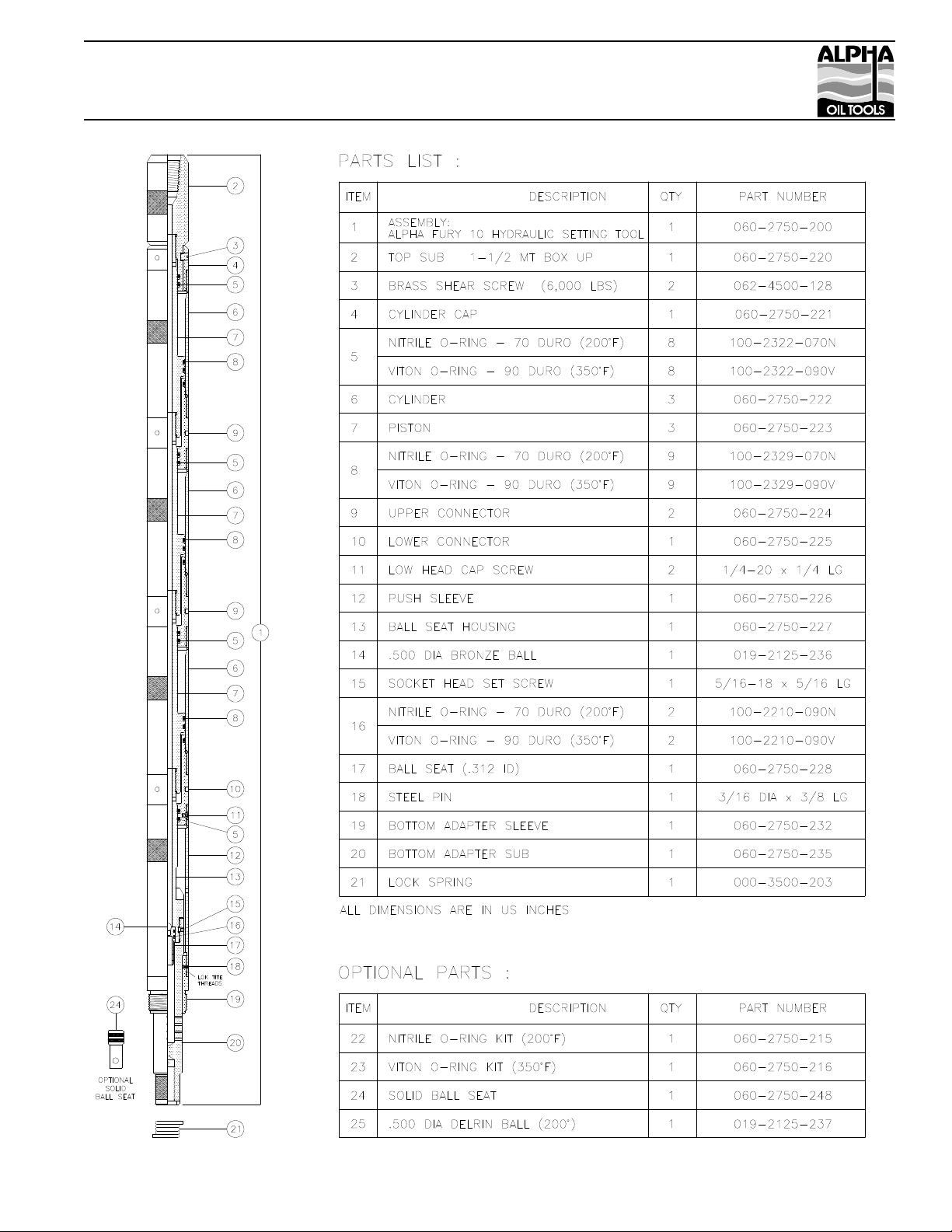
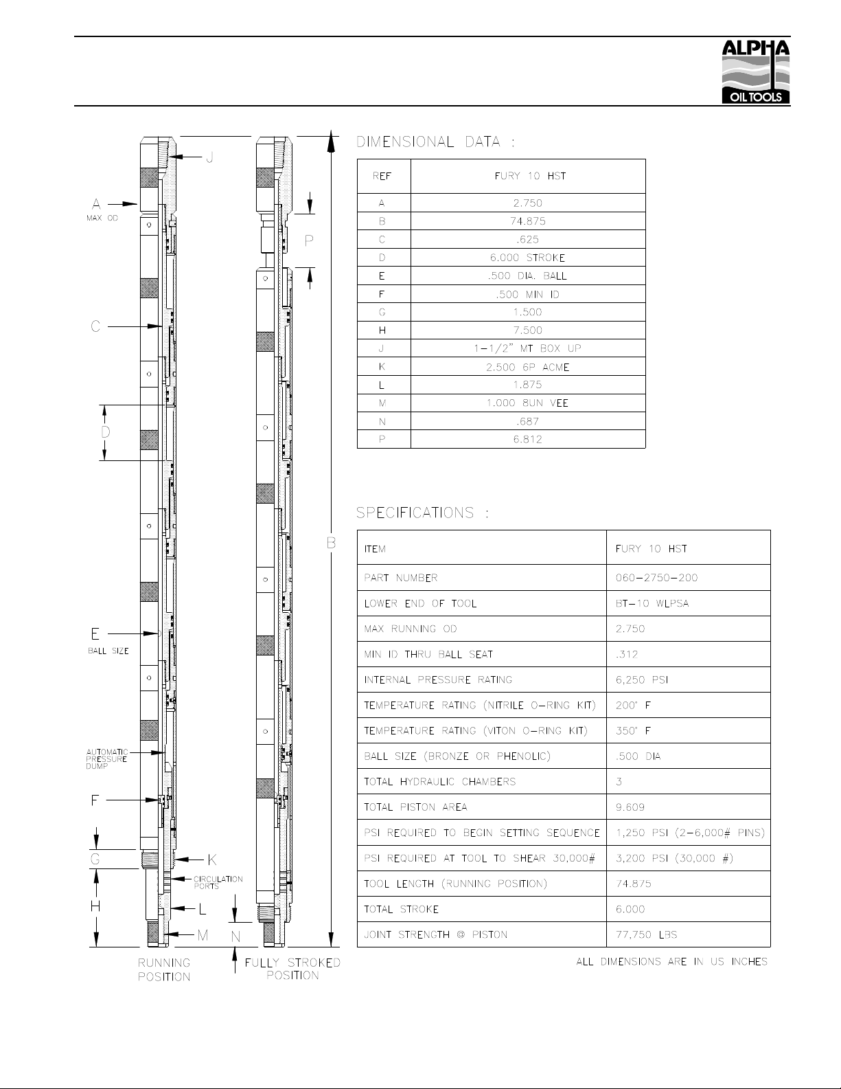
Alpha Fury 10 Hydraulic Setting Tool
Page: 1 of 2
Assembly Instructions :
Reference Alpha Fury 10 Hydraulic Setting Tool Parts List. Drift Cylinder (item 6) with Piston (item 7).
Install all O-Rings. Lubricate all O-Rings, Threads, Sealing and Sliding Surfaces with Mobil Grease HP.
Wrench only where indicated. File away wrench marks. Note: Never use pipe wrench or vise on Cylinder
(item 6) at midpoint. Make Cylinders (item 6) strap wrench tight by locating strap on knurled area of
cylinder. Spanner wrench tight means hand tight then striking spanner handle with rubber mallet two or
three times. Screwdriver tight means hand tight with a medium blade 6” long screwdriver.
1. Place Top Sub (item 2) in vise at box connection. Slide Cylinder Cap (item 4) on Top Sub. Install (2)
Brass Shear Screws (item 3) in groove screwdriver tight then back-off 1/8 turn.
2. Screw first Piston (item 7) in Top Sub wrench tight. Lubricate entire ID of first Cylinder (item 6) with
Mobil Grease HP. Slide Cylinder (item 6) over Piston and screw to Cylinder Cap (item 4). Make strap
wrench tight by holding back up at Cylinder Cap with spanner wrench. Screw first Upper Connector (item
9) in Cylinder and make spanner wrench tight.
3. Screw second Piston (item 7) in previous Piston wrench tight. Lubricate entire ID of second Cylinder
(item 6) with Mobil Grease HP. Slide Cylinder (item 6) over Piston and screw to Upper Connector (item 9).
Make strap wrench tight by holding back up at Cylinder Cap with spanner wrench. Screw second Upper
Connector (item 9) in Cylinder and make spanner wrench tight.
4. Screw third Piston (item 7) in previous Piston wrench tight. Lubricate entire ID of third Cylinder (item 6)
with Mobil Grease HP. Slide Cylinder (item 6) over Piston and screw to Upper Connector (item 9). Make
strap wrench tight by holding back up at Cylinder Cap with spanner wrench. Screw Lower Connector (item
10) in Cylinder and make spanner wrench tight. Note: The Lower Connector (item 10) differs from the
Upper Connector (item 9) with a spot face/tapped hole in the lower thread and the OD is knurled.
5. Slide upper end of Ball Seat Housing (item 13) through Lower Connector (item 10) then screw to lower
end of previous Piston wrench tight. Wrench at knurled area on Ball Seat Housing.
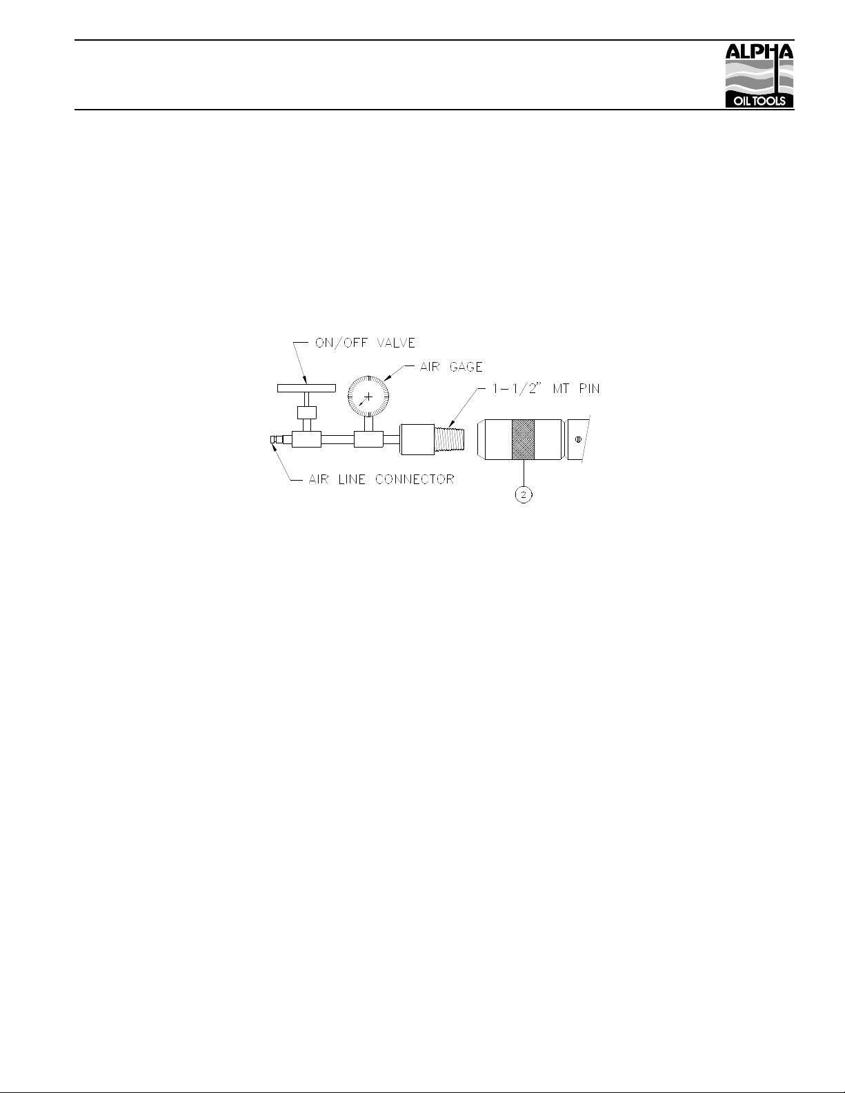
6. Internally test 3-hydraulic chambers with air to check for cut or missing o-rings. Temporally install solid
ball seat (item 24) in lower end of Ball Seat Housing (item 13). Screw Bottom Adapter Sub (item 20) on
Ball Seat Housing (item 13) wrench tight. Wrench at knurled area on Ball Seat Housing. Make sure Top
Sub (item 2) is secure in pipe vise, tighten both brass shear screws (item 3) then connect air test fixture.
Make 1-1/2” MT connection wrench tight and close on/off valve. Connect airline, open on/off valve and
allow air to fill HST, then close valve. If gage is steady for 2-minutes and no flow of air can be heard then
HST is tested. If a steady air test cannot be achieved then HST must be disassembled to find the cause. Bled
air pressure to zero and remove Bottom Adapter Sub (item 20) by placing a back up at knurled area on Ball
Seat Housing. Remove Solid Ball Seat (item 24). Install Ball Seat (item 17) in lower end of Ball Seat
Housing (item 13). Screw Bottom Adapter Sub (item 20) on Ball Seat Housing (item 13) wrench tight.
Install Socket Head Set Screw (item 15).
7. If it is desired to run HST with a solid seat “no ball” then install Optional Solid Seat (item 24) in lower
end of Ball Seat Housing.