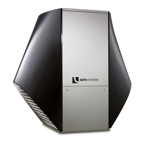
alphainnoTec HT 6Split User manual
Other alphainnoTec Heat Pump manuals

alphainnoTec
alphainnoTec LWP Series User manual

alphainnoTec
alphainnoTec SWP Series User manual
alphainnoTec
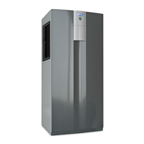
alphainnoTec LWC Series User manual
alphainnoTec
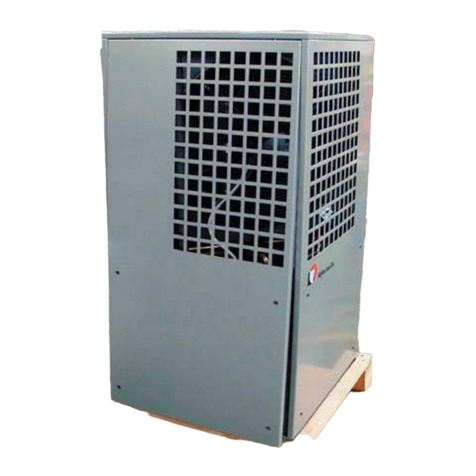
alphainnoTec Solair LW 70M-A User manual
alphainnoTec
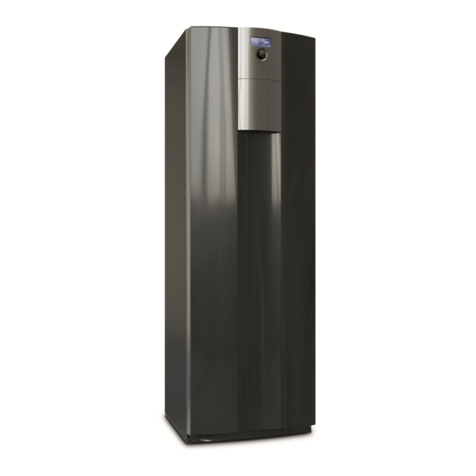
alphainnoTec WZS 42K3M User manual

alphainnoTec
alphainnoTec SW 42H3 User manual
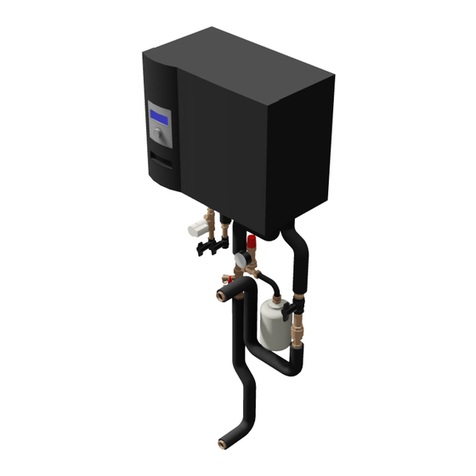
alphainnoTec
alphainnoTec WWB 20 User manual
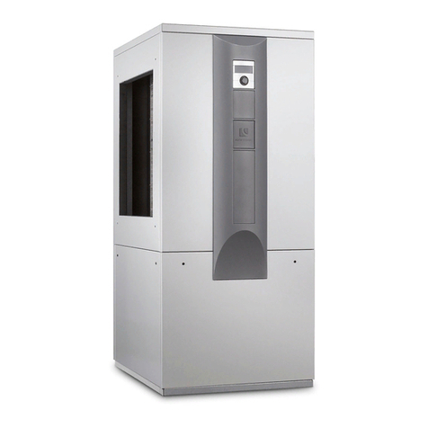
alphainnoTec
alphainnoTec LW 140 User manual
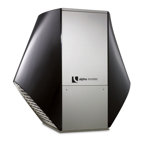
alphainnoTec
alphainnoTec LW A Series User manual

alphainnoTec
alphainnoTec BWP 303+S User manual

alphainnoTec
alphainnoTec SWC V Series User manual

alphainnoTec
alphainnoTec SW 42H3 User manual
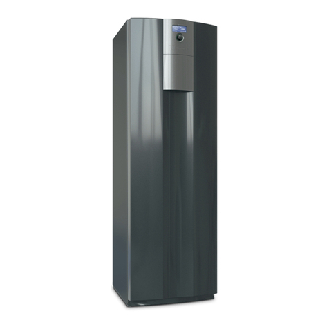
alphainnoTec
alphainnoTec WZS 42H3M User manual
alphainnoTec
alphainnoTec WZS Series User manual
alphainnoTec
alphainnoTec SWC 60H User manual

alphainnoTec
alphainnoTec LW Series User manual

alphainnoTec
alphainnoTec LW 100H User manual

alphainnoTec
alphainnoTec SWC H1 Series User manual

alphainnoTec
alphainnoTec LW 160H/V User manual

alphainnoTec
alphainnoTec LWD 90A User manual
Popular Heat Pump manuals by other brands

Daikin
Daikin RXL12QMVJU Service manual

AIREDALE
AIREDALE BluCube CUR092V16-1CO-0 Installation and maintenance manual

Calyenty
Calyenty RBH 125 Customer's manual

GRE
GRE HPGI50 owner's manual

Carrier
Carrier 30XW Installation, operation and maintenance instructions

Hayward
Hayward SUMHEAT HP5131DT3 Installation instructions manual

REMKO
REMKO SQW 400 Electrical wiring

Sanyo
Sanyo SAP120FCH Service manual

Daikin
Daikin EHYHBH05AA Operation manual

Panasonic
Panasonic WH-SDF03E3E5 Design handbook

Airxcel
Airxcel 45000 Series Installation, operation and maintenance instructions

Mitsubishi Electric
Mitsubishi Electric PUZ-SWM60VAA Service manual

Dimplex
Dimplex LI 16I-TUR Installation and operating instruction

Carrier
Carrier WSHP Open v3 Integration guide

Mitsubishi Electric
Mitsubishi Electric EHSE-YM9EC Service manual

TGM
TGM CTV14CN018A Technical manual

Carrier
Carrier 38MGQ Series installation instructions

Kokido
Kokido K2O K880BX/EU Owner's manual & installation guide
