alphainnoTec Solterra Brine WZ S 75H User manual

Alpha-InnoTec GmbH
Industriestrasse 3, D-95359 Kasendorf
Tel.: +49 (0)9228 99060
Fax.: +49 (0)9228 990629
www.alpha-innotec.de
e-mail:[email protected]
INSTRUCTION MANUAL
with Product Information
Heat station Brine
WZ S 75H
WZ S 75H/S
This instruction manual is part of the scope of supply and must be handed over to the user of the plant.
Please keep safely and show to authorized service-technicians, if necessary.
The future of heat pumps

2-Subject to Technical Modifications - 830133GB/151111
Page
Safety Regulations 2
Scope of Supply / General 3
Transport 4
Installation 6
Installation Plan 7
Assembly Module Box 8
Connection Heating Circuit 9
Connection Brine Circuit 10
Hydraulic Systems / Electrics 12
Assembly Groups Heat station 13
Connections Heat station 14
Hydraulic Schematics 15
System Venting 17
Installation Power Supply 18
Terminal Connection Diagram WZ S 75H 20
Terminal Connection Diagram WZ S 75H/S 21
Operating Element 22
Start up / Maintenance / Trouble Shooting 23
Technical Details 24
Heating Output, Cop 26
Cooling Capacity 27
Pressure Drop Curves 28
View Plan 29
Circuit Diagrams WZ S 75H 30
WZ S 75H/S 35
EC-Declaration of Conformity 40
Guarantee Conditions 41
Notice of Completion 42
In general, the following recommendations are referred to in
this instruction manual.
Safety instructions. Important! Please
observe!
Please observe advice referring to function
and operating method!
Reference to instruction manual of the
heat pump controller
The heat pump installation must be installed and
commissioned by a competent person in accordance
with the current legislation and standards and the
instruction manual.
The use of a heat pump plant must be notified to your
local energy supply company.
The components and pipework of the refrigeration
circle must on no account be used for lifting
purposes.
For safety reasons, the power supply of the heat
pump and of the controller must never be shut off
even outside the heating period.
Opening of the device only by competent persons.
Before opening the device, all electric circuits must
be switched off.
Works on the refrigeration system must be carried
out only by competent persons.
After purging the condenser with a chemical purifying
agent, the neutralization of remainders as well as
intense water rinsing is absolutely necessary.
Never treat the device with scouring, acidic
or corrosive agents.
i
i
TABLE OF CONTENTS SAFETY REGULATIONS

830133GB/151111 - Subject to Technical Modifications - 3
General
Operating Range
The heat pump is designed exclusively for the heating of
heating circuit water and domestic hot water. Considering
the application limits (see technical details), the heat pump
can be installed on new or existing heating installations.
Functioning of the brine / water heat pump
The heat pump converts the low temperature heat of
the ground to a higher temperature. Brine (a mixture of
water and antifreeze agent) is pumped through coils in
the ground and conducted to the evaporator of the heat
pump. The evaporator contains the liquid agent which
boils and vaporizes at low temperatures and low pressure.
The vaporizing heat is transferred from the brine. The
compressor sucks in the vaporized agent and compresses
it to achieve a higher pressure. The compressed gaseous
agent enters the condenser, where it condenses at high
pressure and high temperature. The condensation heat
is transferred to the heating circuit water with resultant
increase in temperature.
The energy transmitted to the heating circuit water
corresponds to the energy transmitted from the brine plus
the small amount of electric energy for the compressor.
Energy-saving use of the heat pump heating
installation
By choosing a heat pump heating installation, you have
acknowledged the need for environmental protection
by lower emissions and less consumption of energy. To
ensure your new heating system works as efficiently as
possible, please note the following:
The heat pump heating installation must be correctly
sized and installed.
Avoid unnecessarily high flow temperatures. The
lower the flow temperature at the heating circuit water
side is, the more efficiently the heat pump works.
The controller must be set correctly!!
Preferably open the window totally to renew the air.
Compared to constantly pivot-hung windows opening
outward, this kind of ventilation reduces the energy
consumption and saves money!
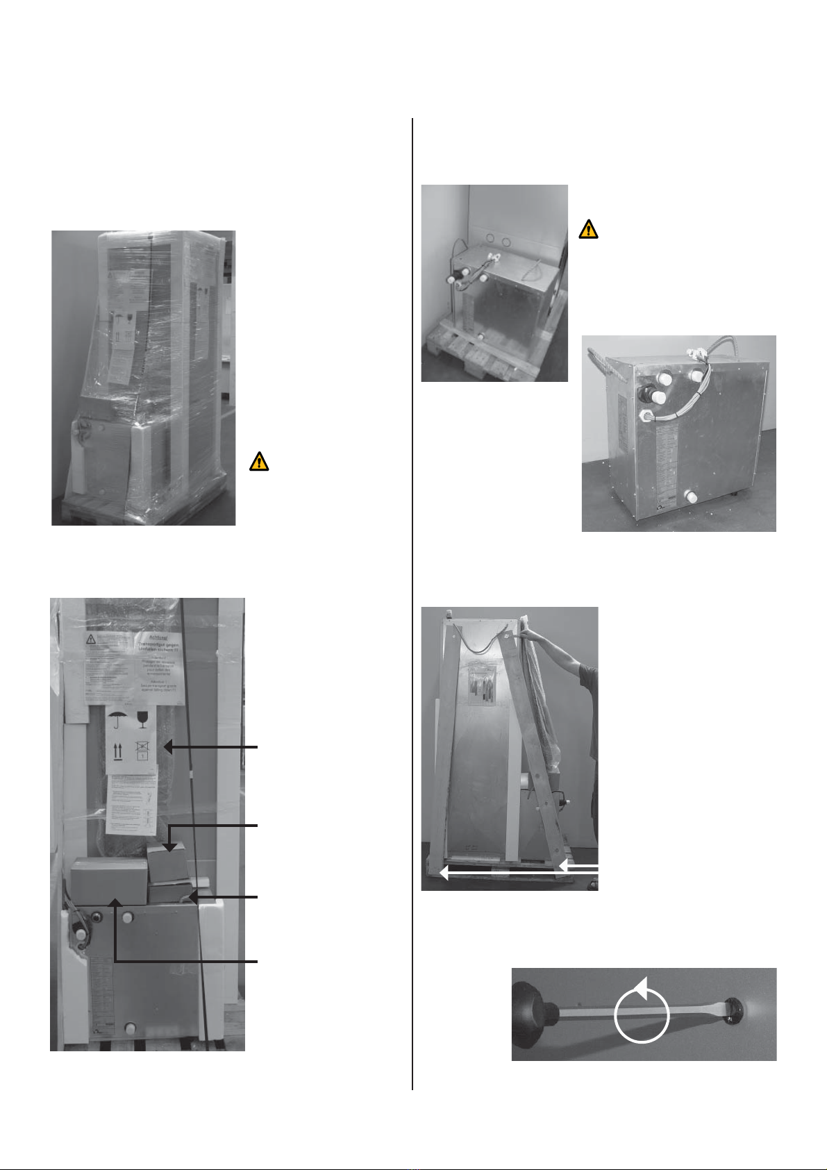
Scope of Supply
• Compact device with module box
• Integrated heat pump and heating installation controller
(during the transport, the outdoor temperature sensor is
stored inside the device)
• Electric switch box with power contactor.
• Integrated brine circuit circulating pump and heating circuit
circulating pump (Note: free pressing - see Technical
Data Sheets)
•
Integrated domestic hot water storage with external current
anode
• Safety components for the heating circuit
• Pressure differential valve for heating circuit
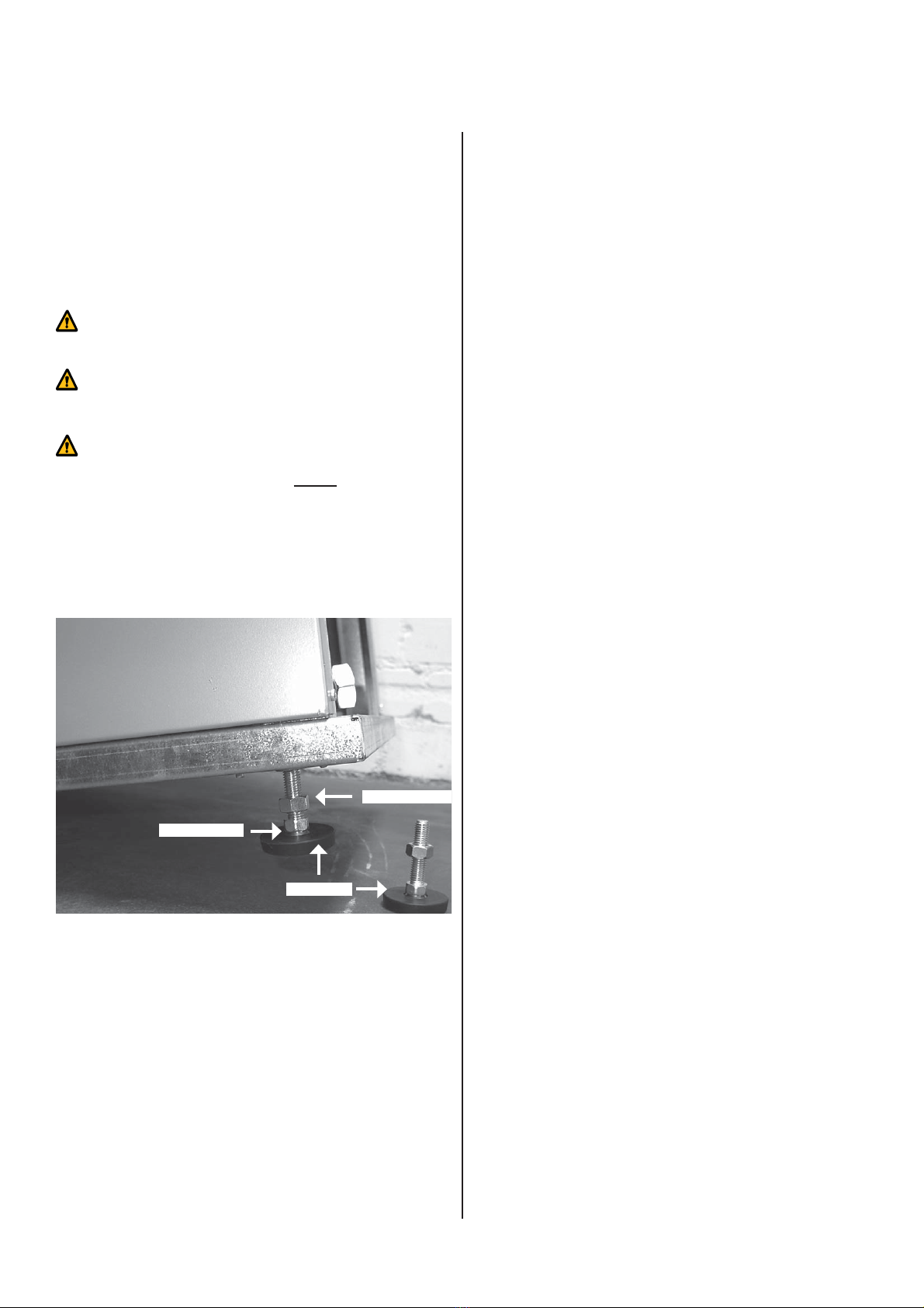
• Adjustable stands
• 3-way reversing valve for domestic hot water heating
• Electrical heating element: 6kW (reversible to 4kW or
2kW))
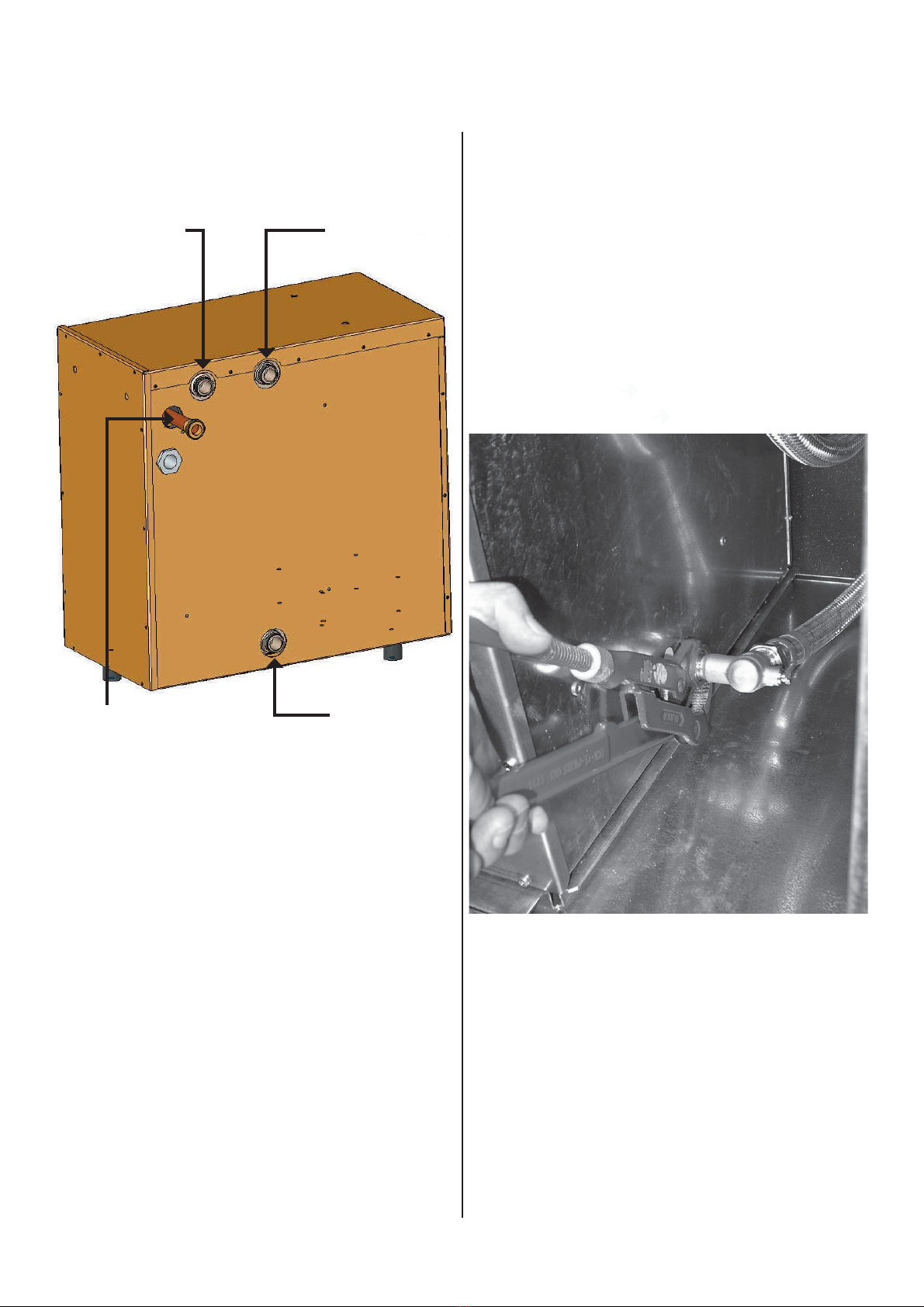
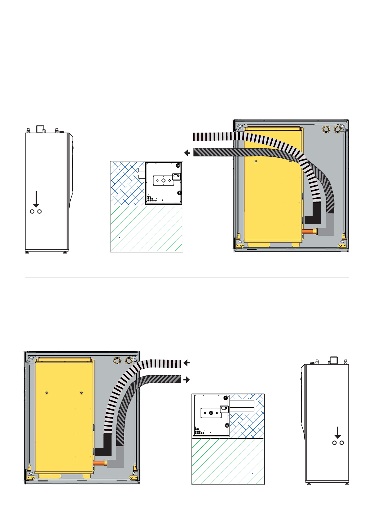
• Connection-set brine:
2 flexible reinforced tubes (stainless steel), pre-insulated
+ insulating material + small parts
• Operating element for heat pump controller
Expansion vessel and safety components for the
brine circuit are not delivered with the unit.
Expansion vessel for the heating circuit is not
delivered with the unit.
Further features:
Sensors inside the device for sensing the hot gas temperature
and heating-circuit water flow and return temperature.
Sensors for monitoring of the heat source temperature and the
hot gas temperature of the refrigeration circuit.
i
SCOPE OF SUPPLY / GENERAL

4-Subject to Technical Modifications - 830133GB/151111
Transport with Lift Truck
To avoid transportation damage, the heat pump should be
transported with a lift truck, in packed condition, on a wooden
pallet.
Note: transportation
with a lift truck only in
packed condition.
The module box and the accessories are besides the heat pump
on the pallet, in packed condition.
Cover plate
Operating Elementl
Heat station controller
Heating safety
components
Small parts:
- 4 stands
- 1 outdoor sensor
- 1 insulating set
- 2 ball valves
- 8 washers
-
1 service tube
Remove the plastic sheeting. Take the module box and the ac-
cessories off the pallet.
Module box unpacked:
The module box must not be
inclined by more than 45° during
the transportation.
Remove screwing at the safety crate with an open-end adjustab-
le wrench (wrench size 13).
Remove the Spax-screws.
Open the quick-release screws on the front by turning anticlock-
wise (90°), lift the service door and put it down safely.
Open the quick-release screws.
TRANSPORT

830133GB/151111 - Subject to Technical Modifications - 5
Lift the front panel:
Remove the safety strips. Two persons at least are needed to lift
the device from the pallet.
Note: danger of tilting! For tilting or laying down the
device, 2 persons must support the heat pump at the
rear side!
Consider the weight of the heat pump!
(see technical data sheet).)
Horizontal transportation of the basic device is possible
W I T H O U T M O D U L E B O X!
Transport with the pallet truck
We recommend to lift the front plate (weight reduction). Put the
heat pump on the pallet truck with open front plate and transport
it to the installation site.
Note: transport with the pallet truck is admissible
only at the rear side.
Note: secure the heat pump to the pallet truck
against slipping down.n
The components and pipework of the refrigeration
circle, the heating side and the heat source side must
on no account be used for lifting purposes.
TRANSPORT

6-Subject to Technical Modifications - 830133GB/151111
Installation
The heat pump must be installed on a sustainable and horizontal
underground. Small unevennesses may be levelled by the
enclosed stands.
The installation site must be frost-proof and dry.
The heat pump must not be installed on a PUR boiler
platform.
Note: shifting of the device without stands may
damage the floor!
2 persons are needed to mount the stands, one per-
son securing the slightly tilted device.
The stands must be installed before inserting the mo-
dule box to avoid tilting of the box and damage of the
device.
Mount the stands and install the device at the installation site.
Align the device with the four set-screws; then screw down the
counter nut (SW19).
INSTALLATION
Set-screw
Counter-nut
Stand

830133GB/151111 - Subject to Technical Modifications - 7
INSTALLATION PLAN
Raumhöhe min. 2150
Version 1
Oberkante Fertigfußboden
Bord supérieur sol
Upper edge finished floor
Hauteur de la pièce 2150 au minimum
Room height min. 2150
2050
Version 2
> 1200
>20
>20
> 1200
> 1500
>20
>20
-schraffierte Fläche
Freiraum für
funktionsnotwendiges
Zubehör
-surface hachure section
pour accessoires nécessaire
pour le bon fonctionnement
-hatched section clear
area for necessary
accessories for operating
-schraffierte Fläche
Freiraum für
Servicezwecke.
-Section hachure espace libre
pour service après vente.
-Hatched section clear area
for maintenance.

8-Subject to Technical Modifications - 830133GB/151111
Installation of the module box
Before fitting in the module box, take out the two flexible rein-
forced tubes for the heat source.
Note: when fitting in the module box, the rubber feet must be
positioned in accordance with the base plate drawing. The front
rubber foot must be fitted in between the two guide angles.
Top view base plate:
Front rubber foot of the module box
To avoid damage, the module box must not be inclined
by more than 45° during the transportation!
Lift the two rear rubber feet above the front edge of the centering
sheet steel in the casing bottom to be able to fit the module box
in the heat station casing.
Please note the
position of the
plugs when fitting
in the module box!
Fit in the module box until the front rubber foot needs to be
lifted above the centering sheet steel. The module box is placed
correctly as soon as the front rubber foot has snapped in the
centering sheet steel.
Never transport the device after the module box has
been fitted in!
ASSEMBLY MODULE BOX
Flexible reinforced tubes for
the heat source
Remove the protective plastic
sheeting at the heating water
tubes..
Rear rubber feet of the
module box
Centering
sheet steel
Stop

830133GB/151111 - Subject to Technical Modifications - 9
Connection of the enclosed tubes:
HYDRAULIC CONNECTION POINTS AT THE MODULE BOX
Heat source inlet Heating circuit water outlet
(flow)
Heat source outlet Heating circuit water inlet
(return)
Heating circuit water supply point
First of all, connect the heating circuit water circuit to ensure bet-
ter accessibility .
The two flexible reinforced tubes for connection to the heating cir-
cuit are inside the device. Use two washers for the connection.
Note the inlet- and outlet-side of the heating circuit when faste-
ning the connections!
blue (beneath) = heating circuit water inlet (return)
red (top) = heating circuit water outlet (flow)
Elektro- / Fühlerleitungen
CONNECTION HEATING CIRCUIT

10 -Subject to Technical Modifications - 830133GB/151111
The connection to the heat source installation (brine circuit) is
possible at the right hand or left hand device side (optional).
LEFT HAND brine tube laying
Brine-inlet
Brine-outlet
RIGHT HAND brine tube laying
Brine-inlet
Brine-outlet
CONNECTION BRINE CIRCUIT
Ansicht von oben
im Schnitt:
Ansicht von oben
im Schnitt:

830133GB/151111 - Subject to Technical Modifications - 11
CONNECTION BRINE CIRCUIT
The connection to the piping of the brine circuit must be carried
out by the flexible tubes delivered with the unit.
First of all, the circular blanks of the tube ducts must be removed
on the chosen connection side.
Note: do not leave any excess ends to ensure trouble-
free inserting of the plastic rosettes.
The two brine connection tubes should be fitted in from the
outside to the inside
and fastened to the corner ball valve. Use the enclosed
washers.
The insulated flexible reinforced tu-
bes of the brine circuit are led out-
side through the plastic rosettes.
The tubes should be led in
a quarter circle to decoup-
le the module box from the
rigid piping system.
Tighten the screwings of the tube connections with a spanner.
Note the correct inlet- and outlet-side of the brine circuit and use
the enclosed washers!
When connecting the flexible reinforced tubes, the
connection point on the heat pump must be secured
against torsion with a spanner in order to avoid
damage to the copper pipe on the heat source outlet.
The heat source installation must be designed in accordance
with the project planning manual.
Please note:
• Before filling the heat source installation, it must be rinsed
thoroughly.
• A strainer (sieve size < 1 mm) must be installed in front of
the heat pump inlet on the brine side (not delivered with the
unit).
The water/antifreeze-mixture (brine) must be mixed
thoroughly before filling in the heat source installation.
• The brine concentration must be minimum 25%,
• The cross-section and the length of the tubes of the
heat source installation must be sized correctly, i.e. the
pressure of the integrated brine pump must achieve
the nominal brine flow rate.
• Expansion vessel and safety components are not
delivered with the unit.
Device Nominal
brine flow Free pressure
WZ S 75H/S 1800 0,37 bar

12 -Subject to Technical Modifications - 830133GB/151111
Open the 4 corner ball valves after having
tightened them at the module box.
Open the ball valve anticlockwise (90°) with a spanner.
Ball valve closed Ball valve open
(slot longitudinal axis)
Open the corner ball valves and make a pressure test; before the
start-up, insulate the corner ball valves of the heat source side
with the enclosed insulating material (diffusion-proof).
Connection of electrics:
Push the 3 electric attaching plugs in the plug connections (at the
bottom side of the intermediate bottom).
Removal from the module box
Dismantling of the module box reciprocally, i.e.:
Close the 4 ball valves and drain the module box before discon-
necting the tubes.
> Drainage by the corner ball valve.
Mount the maintenance tube for venting or draining:
HYDRAULIC SYSTEMS / ELECTRICS

830133GB/151111 - Subject to Technical Modifications - 13
Ducts for electric
cables / sensor cables
Switch box
r
temperature sensor
sanitary hot waters torage
Maintenance opening sanitary
hot water storage
Drainage
Domestic hot water storage
Impressed-current anode
under the cap in the top
3-way-switching valve
Heating / domestic hot water
Circulating pump
Heating / domestic hot water
Sanitary hot water storage
Pressure differential valve
Heating element
Flushing ball valve
ASSEMBLY GROUPS OF THE HEAT STATION
Safety temperature limiter
Pump failure: check whether the RE-
SET-BUTTON of the electric heating
element has jumped out - if so, push
it in again!

14 -Subject to Technical Modifications - 830133GB/151111
CONNECTIONS HEAT STATION
Connection to the heating system
The heating side connection is on the top of the device.
Heating circuit water-Inlet (Return)
t
Impressed-current anode
under the cap Heating circuit water-
Outle
(Flow)
Duct for electric cables/
sensor cables Connection
safety components
Venting valves must be attached on top of the heat
station!
Note: Hold up the device when attaching the
heating circuit water connections and the safe-
ty components.
The domestic hot water storage is integrated.
Please note the following on the heating side:
• The heating system must be flushed before connecting
the heat pump to prevent contamination inside the
heating system affecting the function of the heat
pump.
• On the heat pump side, flow and return must be
equipped with isolating valves to allow eventual flush-
ing of the internal heating circuit.
• The heating installation must be sized correctly, i.e.
the pressure of the integrated circulating pump must
achieve the nominal heating circuit water flow rate.
• The expansion vessel for the heating circuit water is
not delivered with the unit.
Device Nominal heating
circuit water flow Free pressure
WZ S 75H/S 700 l/h 0,3 bar
cold warm
sanitary hot water

830133GB/151111 - Subject to Technical Modifications - 15
HYDRAULIC SCHEMATIC
Heat station brine, single source operation, 1 heating circuit,
domestic water heating and passive cooling
g
Domestic
hot water
tank
Refrigeration system module
box, removable
Integral within heat station
1) Heat pump with flow and return sensor for the heating system
2) Radiator or floor heating
3) Vibration-free connection (flexible connections)
4) Sound-absorbing support (only for elevated sound intensity)
5) Gate valve with drain device
6) Expansion vessel
7) Safety valve
8) Gate valve
9) Heating circulating pump
10) Non-return valve
11) Thermostatic valve / single room temperature control
12) Pressure differential regulating valve
13) Vapour-proof insulation
14) Domestic hot water circulating pump
15) Three-way mixer (mixing circuit)
16) Mixer motor
17) 2nd heating circuit with tv<tv 1st heating circuit
18) Immersion heating element heating
19) Four-way mixing valve
20) Immersion heating element domestic hot water
21) Circulating pump mixing circuit
22) Circulating pump swimming pool
23) Feeder circulating pump
24) Manometer
25) Heating circulating pump and domestic hot water
26) Switching valve domestic hot water
27) Immersion heater for heating and domestic hot water
28) Brine circulating pump
29) Strainer (1 mm sieve size)
30) Storage tank for brine liquid
31) Wall penetration
32) Supply pipe PE-MR PN 10
33) Brine distributor with filling and drain device
34) Collector pipe PE MRS8
35) Permanent aspirator
36) Well pump (corrosion-proof immersion pump)
37) Thermostat 0°C - 16°C
38) Flow switch
39) Suction well pipe
40) Absorption well pipe
41) Flushing valve heating circuit
42) Circulating pump
A Outside wall sensor
B Domestic hot water sensor or thermostat
C Flow sensor (mixing circuit)
D Floor temperature limiter
The heat exchanger surface of the domestic hot water storage must be adapted to
the heating output of the heat pump!
All pipe work must be sized correctly to achieve minimum water flow rate through
the heat pump!

16 -Subject to Technical Modifications - 830133GB/151111
HYDRAULIC SCHEMATICS
Heat station brine, with cooling kit
Single room temperature control,
suitable for heating and cooling
Dew point guard - accessory (optional)
Integral within the coo-
ling kit (accessory) Antifreeze
thermostat + 5°C
Domestic
hot water
tank
Refrigeration system module
box, removable
Integral within heat station
1) Heat pump with flow and return sensor for the heating system
2) Radiator or floor heating
3) Vibration-free connection (flexible connections)
4) Sound-absorbing support (only for elevated sound intensity)
5) Gate valve with drain device
6) Expansion vessel
7) Safety valve
8) Gate valve
9) Heating circulating pump
10) Non-return valve
11) Thermostatic valve / single room temperature control
12) Pressure differential regulating valve
13) Vapour-proof insulation
14) Domestic hot water circulating pump
15) Three-way mixer (mixing circuit)
16) Mixer motor
17) 2nd heating circuit with tv<tv 1st heating circuit
18) Immersion heating element heating
19) Four-way mixing valve
20) Immersion heating element domestic hot water
21) Circulating pump mixing circuit
22) Circulating pump swimming pool
23) Feeder circulating pump
24) Manometer
25) Heating circulating pump and domestic hot water
26) Switching valve domestic hot water
27) Immersion heater for heating and domestic hot water
28) Brine circulating pump
29) Strainer (1 mm sieve size)
30) Storage tank for brine liquid
31) Wall penetration
32) Supply pipe PE-MR PN 10
33) Brine distributor with filling and drain device
34) Collector pipe PE MRS8
35) Permanent aspirator
36) Well pump (corrosion-proof immersion pump)
37) Thermostat 0°C - 16°C
38) Flow switch
39) Suction well pipe
40) Absorption well pipe
41) Flushing valve heating circuit
42) Circulating pump
A Outside wall sensor
B Domestic hot water sensor or thermostat
C Flow sensor (mixing circuit)
D Floor temperature limiter
The heat exchanger surface of the domestic hot water storage must be adapted to
the heating output of the heat pump!
All pipe work must be sized correctly to achieve minimum water flow rate through
the heat pump!
see hydraulics heat source installation

830133GB/151111 - Subject to Technical Modifications - 17
The installation must be completely VENTED before
the start-up. A scavenging ball valve is integrated in
the heat station for this purpose.
For flushing the installation, cock 3 must be closed and the ball
valves 1 and 2 must be opened.
A tube for the water inlet is connected to cock 2. A tube for water
outlet is connected to cock 1. This tube should be led to a drain.
When flushing the installation, a maximum pressu-
re of 2,5 bar must not be exceeded. The safety valve
must be connected before flushing.
After completion of the manual flushing and before
starting the venting program (heat pump controller)
the ball valves must be brought back to their original
position.
The cutoffs above the heat station or at the floor heating dis-
tributor must be closed to allow flushing of the internal heating
circuit.
Hand lever right: Hand lever left (hold back with
(normal position) your thumb)
Flushing / venting of Flushing / venting of the loading
the heating circuit circuit of the domestic hot water
storage
In central position of the hand lever, the domestic hot water
storage and the heating circuit are being flushed simultane-
ously.
This operation is supposed to take about 3 to 5 minutes.
We recommend to hold back 1 minute also the lever of the
switching valve to ensure complete venting of the domestic
hot water loading circuit.
After termination of the flushing, the lever must be reset for-
ward (at the right).
After completion of the flushing of the heat station, start the
venting program at the heat pump controller.
SYSTEM VENTING
1
2
3

18 -Subject to Technical Modifications - 830133GB/151111
Installation and electric works must be carried out
by competent persons and in accordance with all
safety and IEE* regulations.
*IEE – Institute of Electrical Engineers
Please secure right-hand rotating field of the load supply.
The supply of the heat pump must be equipped with an all-pole
switching-off with minimum 3 mm contact opening distance and a
3-pole overload release. Please find the relevant starting current
on the respective technical data sheet.
The connections of the supply lines and control lines of the heat
pump and the ambient temperature sensor must be connected in
accordance with the terminal connection diagram in the product
information sheets.
The cables are lead through the screwed cable glands on top of
the device and over the cable duct to the clamps.
Strain relief by the screwed cable glands.
Screw off the cover plate:
Remove the lower screws and loosen the two upper screws
slightly to hang the cover plate out.
INSTALLATION POWER SUPPLY

830133GB/151111 - Subject to Technical Modifications - 19
In the switch room WZ S 75H/S:
Terminal strips for the connection of working stress and control
voltage (see terminal connection diagram).
soft
starter
The heating element is serially
clamped to 6kW.
The label on the heating ele-
ment explains how to modify
the heating element to 2 / 4 / 6
kW.
Connection / disconnection
at contac K5t
Control
Compressor 1PE
Supplementary
heating 1NPE
N / PE
After finishing the electric installation, the switch
room covering must be reassembled and the device
must be closed.
Reattach the cover plate and screw tightly.
INSTALLATION POWER SUPPLY

20 -Subject to Technical Modifications - 830133GB/151111
N
ASD
PEX
VBO
ZW1
HUP
FP1
ZUP/ZIP
MA1
MZ1
BUP
ZW2/SST
GND
RFV
GND
TB1
GND
BWT
GND
TA
GND
TRL
GND
MOT
EVU
N
PE
N
N
N
N
N
PE
PE
PE
PE
PE
N
WP-Absicherung mit 3-pol.
Leitungsschutzschalter.
Achtung Rechtsdrehfeld
ist zwingend notwendig!
Hausinstallation
Unterverteilung
geschlossen
Sperre
EVU-
Freigabe WP
EVU-Sperre
Kontakt bei
Aussenfühler
Brauchwasserfühler/-thermostat (intern verdr.)
Steuerung 230 V
EVU-Sperre
Last Verdichter
3 x 400 V
E
P
L
1
L
1
E
P
L
1
2
L
L
3
Fürhler Mischer1 (Zubehör)
Raumfernversteller (Zubehör)
Heizungsumwälzpumpe
Fußbodenheizungspumpe
Zusatzumwälzpumpe
Brauchwasserumwälzpumpe
Soleumwälzpumpe
Zweiter Wärmeerzeuger 1
Wärmeerzeuger 2 / Sammelst.
Mischer 1
AUF
Mischer 1
ZU
externer Rücklauffühler
43
2
interne Verdrahtung
Anschlussklemmen in WP Anschlussklemmen auf Platine
Zweiter Wärmeerzeuger 2
(alternativ Sammelst.)
M
Lade-/
Entlademischer
Raumstation (Zubehör)
L
1
L
1
Pumpe für
Entlademischer
N-/PE-Verteilung in Wärmepumpe
für Anschluß externer 230V-Geräte
(z.B. Pumpen/Mischer)
WP-Absicherung 10A / C (Träge)
Soledruckpressostat
Motorschutzschalter
P
Soledruck-Pressostat
Last Heizelement
3 x 400 V
L
1
2
L
L
3
E
P
5
Absicherung Heizelement 10A / C (Träge)
Potenziostat Fremdstromanode (intern)
INSTALLATION POWER SUPPLY / TERMINAL CONNECTION DIAGRAMM
WZ S 75H 400V / 3ph
The installation and execution of electric works must be carried out by an authorized qualified enginee-
ring specialist, following the relevant EN- and VDE* safety instructions and the “Conditions for Techni-
cal Connections” of the local utility companies.
*German association of electricians
Control 230V
Interior installation
subdivision
off-time by
energy supply
company (local
utility company)
contact closed at
release heat pump
external return sensor
remote setting control (accessories)
terminal clamp on circuit boardterminal clamps in HP
Load copmpressor
3 x 400 V
second heatgenerator1
Heating circulation pump
service water circulation pump
Mixer 1 Open
Mixer1 Closed
suppl.-/circulation pump
heatgenerator2 / collector fault
Floor heating heat pump
brine circulation pump
second heatgenerator2 (alternativ
collector fault)
internal wiring
Pump for
discharge
mixer
sanitary hot water sonsor/-thermostat(accessories)
outside sensor
sensor mixer1/(accessories)
room station /accessories)
HP protection: 10 A//C (inactive)
heating element protection: 10 A//C (inactive)
charge-
/discharge
mixer
N-/PE-distribution in heat pump for
connection of external 230V-devices
(for example pumps/mixers)
HP protection with 3-pole line
safety switch Attention: right-
hand rotating field is impera-
tive
brine pressure press.
EVU-
off-
time
Load copmpressor
3 x 400 V
off-time by energy supply company
brine pressure press.
motor protection switch
This manual suits for next models
1
Table of contents
Popular Heating System manuals by other brands

Maico
Maico WS 320 Additional information

Caladair
Caladair EXAECO 10 Operating and Commissioning Instructions

Honeywell
Honeywell Y9120H Sundial RF2 Pack 1 user guide

Hoval
Hoval TopVent TV operating manual

BrookVent
BrookVent aircycle ONE+ 100 Installation, maintenance & user manual

Suevia
Suevia 317 Mounting instructions