ControllerController
©Aqua-Hot® 125-GN1 Service Manual
REV 220427
©Aqua-Hot® 125-GN1 Service Manual
REV 220427
p. 15p. 14
The Aqua-Hot Controller
Introduction:
The Aqua-Hot 125GN operates on a controller platform
which has been modernized and updated from the previously
used Electronic Controllers and Relay Control Boards of older
Aqua-Hot units.
This controller is best utilized with the Aqua-Hot 3.5in
display. Using the Aqua-Hot with this new display will ensure
that you can take advantage of all of the tools and features of
this controller.
Features:
This new controller brings with it new features to it which
effect functionality from every stage of operation. Fail safe
functionality, climate control, and troubleshooting and
diagnostics have all been overhauled on this new control
architecture. These features will be explained in detail below.
Troubleshooting:
The new troubleshooting functionality is perhaps the largest
and most substantial change to come about from the new
controller architecture. Many faults and failures within the
Aqua-Hot can now be relayed in plain language to the technician
servicing the Aqua-Hot. There are ve system faults which will
Figure 16
Figure 17
be utilized; System Voltage, Low-Level Cutoff, Over-Current,
Overheat, and Burner Failed to Ignite. These will be explained
below.
System Voltage:
System voltage faults indicate that there is a
problem with the RV-side power supply which
powers the Aqua-Hot.
The Aqua-Hot can only operate within a
voltage range of 11V DC to 16V DC. If voltage
drops below 11V, or exceeds 16V DC, the
controller will shut down the Aqua-Hot as a
safety mechanism.
Low-Level Cutoff:
The Low-Level Cutoff fault will only trigger if
the minimum uid level within the Aqua-Hot
is below an acceptable operational threshold.
If the controller is showing a low-level cutoff
fault, begin by diagnosing the oat sensor.
Over-Current:
Over-current faults are triggered by an output
channel (pump, fan, etc) that is attempting
to draw too much current through the
controller. This fault will be accompanied by
the component which triggered the fault,
for example “PUMP 2 OVER-CURRENT” will
display if Pump 2 is not operating correctly.
If over-current faults are appearing on the
display, troubleshoot the offending component
listed as being over-current.
Overheat:
Overheat faults indicate that the unit has
exceeded its overheat threshold of 210°F.
If an overheat condition has occurred,
diagnose the cause of the overheat by
investigating the heating sub-systems of the
Aqua-Hot (electric and/or gas burner).
Under-Current
Under-current faults indicate that the unit
does not have enough voltage to properly
operate. If voltage drops below 11V, the
controller will shut down the Aqua-Hot as a
safety mechanism.
If an under-current fault is displayed on the
screen, troubleshoot the offending component
listed and also check power into the Aqua-Hot.
The fault codes shown above will cover the most common
Aqua-Hot related issues. For more complex issues, it may be
necessary to utilize the DIAG screens, which will be explained
next.
Diagnostic Screens (DIAG)
The diagnostic screens will show the current operational status
of different elements within the Aqua-Hot. By comparing these
operational statuses against the expected results it is possible
to discern operational issues.
Shown below are the diagnostic screens. From these screens it
is possible to see the current status of elements within both the
Aqua-Hot and the status of certain elements within the RV such
as zone thermostats and on/off signals. Each element on the
screens listed below will be explained in detail.
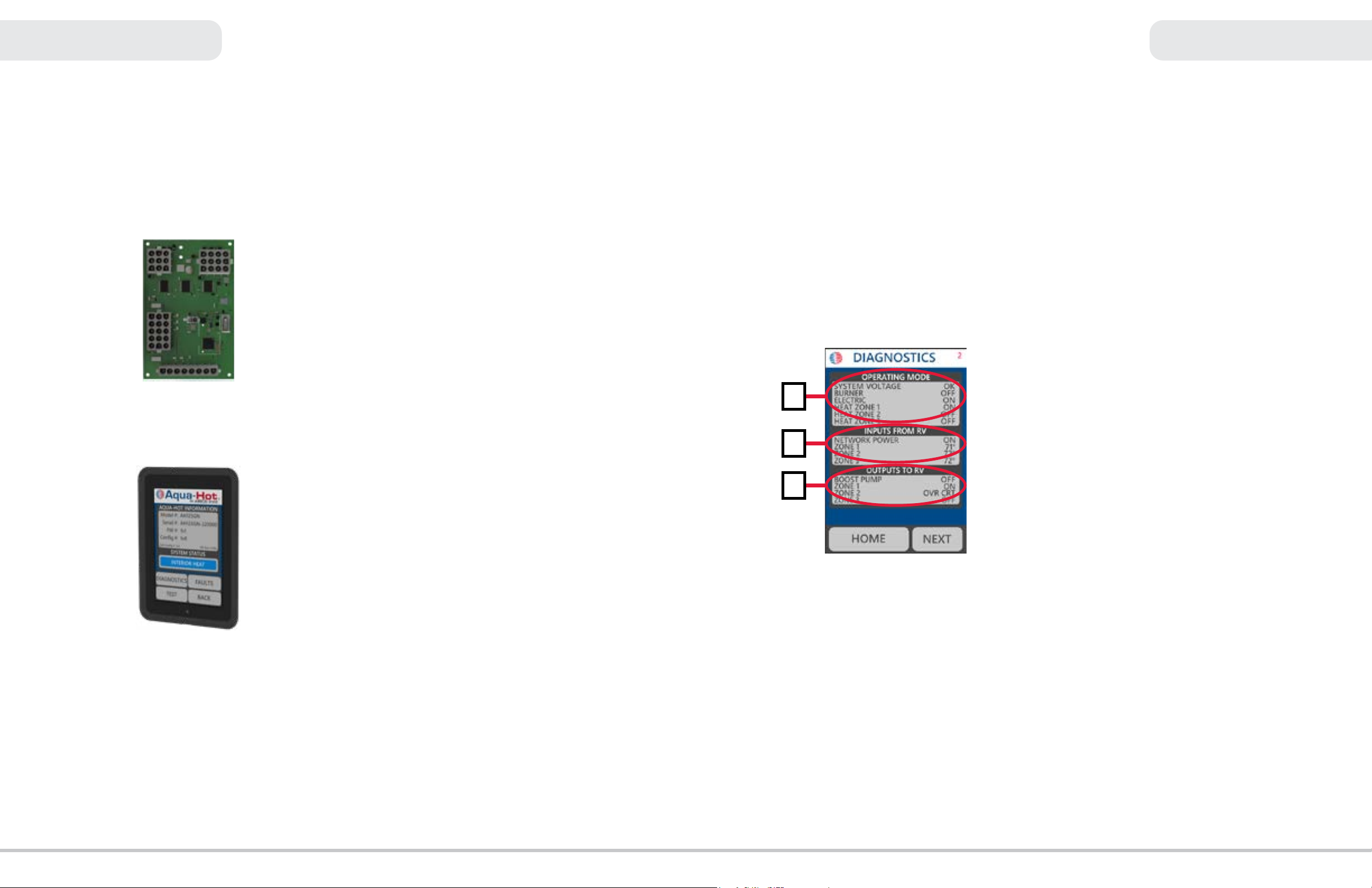
Operating Mode (A):
The operating mode contains six items which relay at-a-glance
information about the function of the Aqua-Hot.
System Voltage:
This section of the Operating Mode page
indicates the status of the supply voltage to the
Aqua-Hot. This will display “OK” if the supply
voltage is between 11V DC and 16V DC.
If this element displays anything except “OK”
begin troubleshooting the RV-side voltage.
Burner:
This indicates the current burner status as
either ON, OFF or FAULT. ON indicates that the
burner is active, and able to re to provide heat.
OFF indicates that heat is either not required or
not requested by the controller.
FAULT indicates that there is an issue with the
burner.
Electric:
The Electric section indicates the controller’s
current handling status of the AC electric relay.
This status indicates that the controller is
attempting to activate the element relay only.
This does NOT indicate whether the electric
element is in working order or not.
Heat Zone #:
The next three elements indicate the current
status of the heating zones (maximum 3).
This element (ON or OFF) only indicates that
the zone thermostat is requesting heat, AND
that the controller is providing power to the
zone fans.
Inputs from RV (B):
The Inputs from RV section will display the signals received
from within the RV as pertaining to the RVC network and the
heating zone thermostats.
With respect to the zones, there will be three different items
displayed next to the Zone # items depending on the type of
RV-side thermostat in use.
• ON: This indicates that the zone is active, and the zone
thermostat is calling for heat
• OFF: This indicates that heat is either not needed, or not
requested by the zone thermostat
• 71°: This indicates the set-point of the RV thermostats.
The example in Figure 18 is showing the RV thermostat
is requesting it be 71°F in Zone 1. This is only available
with certain RV thermostats.
Outputs to RV (C):
The Outputs to RV indicates that the controller is sending power
to components within the RV. This section may also show faults
with components in each zone.
In the example in Figure 18, the controller is not sending power
to the boost pump, so the boost pump is shown as OFF.
Zone 1 is ON, meaning that the controller is sending power to
the Zone 1 fans.
Zone 2 is Over Current, indicating that there may be a problem
with the fans in this zone.
Zone 3 is not active. The controller is not receiving a request for
heat from the RV, and it is not powering the zone fans.
Figure 18
A
B
C