Alphatron ALPHACALL MF User manual

ALPHACALL MF
Installation & operations manual
ALPHATRON MARINE B.V.
Schaardijk 23
3063 NH ROTTERDAM
The Netherlands
Tel: +31 (0)10 – 453 4000
Fax: +31 (0)10 – 452 9214
P.O. Box 210003
3001 AA ROTTERDAM
Web: www.alphatronmarine.com
Mail: info@alphatronmarine.com
The information in this manual is subject to change
without further notice. No rights can be derived from
this manual.
Document : ALPHACALL MF Manual
Revision : 1.0
©ALPHATRON MARINE B.V.

ALPHACALL MF manual version 1.0 Page 2 of 22
ALPHACALL MF
Table of contents:
1VERSION CONTROL ....................................................................................................4
2INTRODUCTION............................................................................................................5
2.1 Options....................................................................................................................5
3INSTALLATION..............................................................................................................6
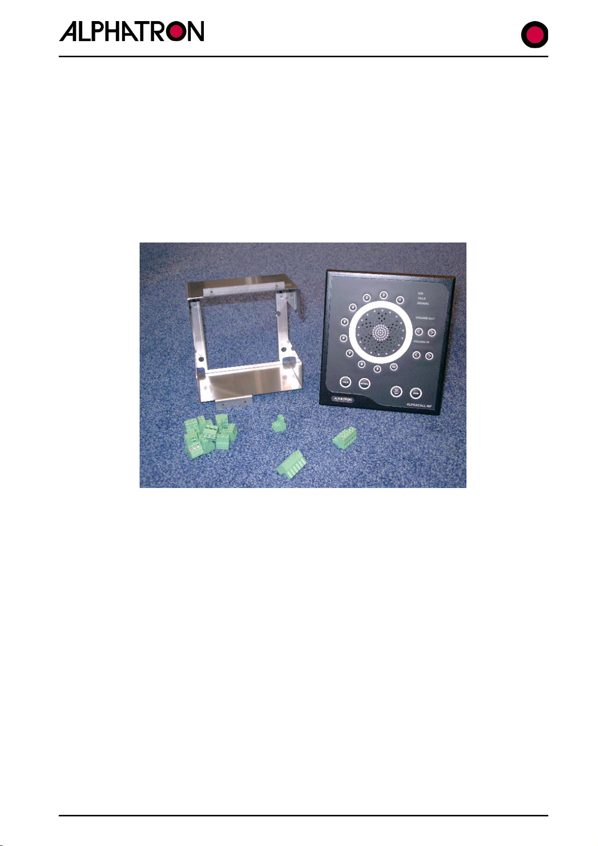
3.1 Materials supplied...................................................................................................6
3.2 Installing the ALPHACALL MF................................................................................7
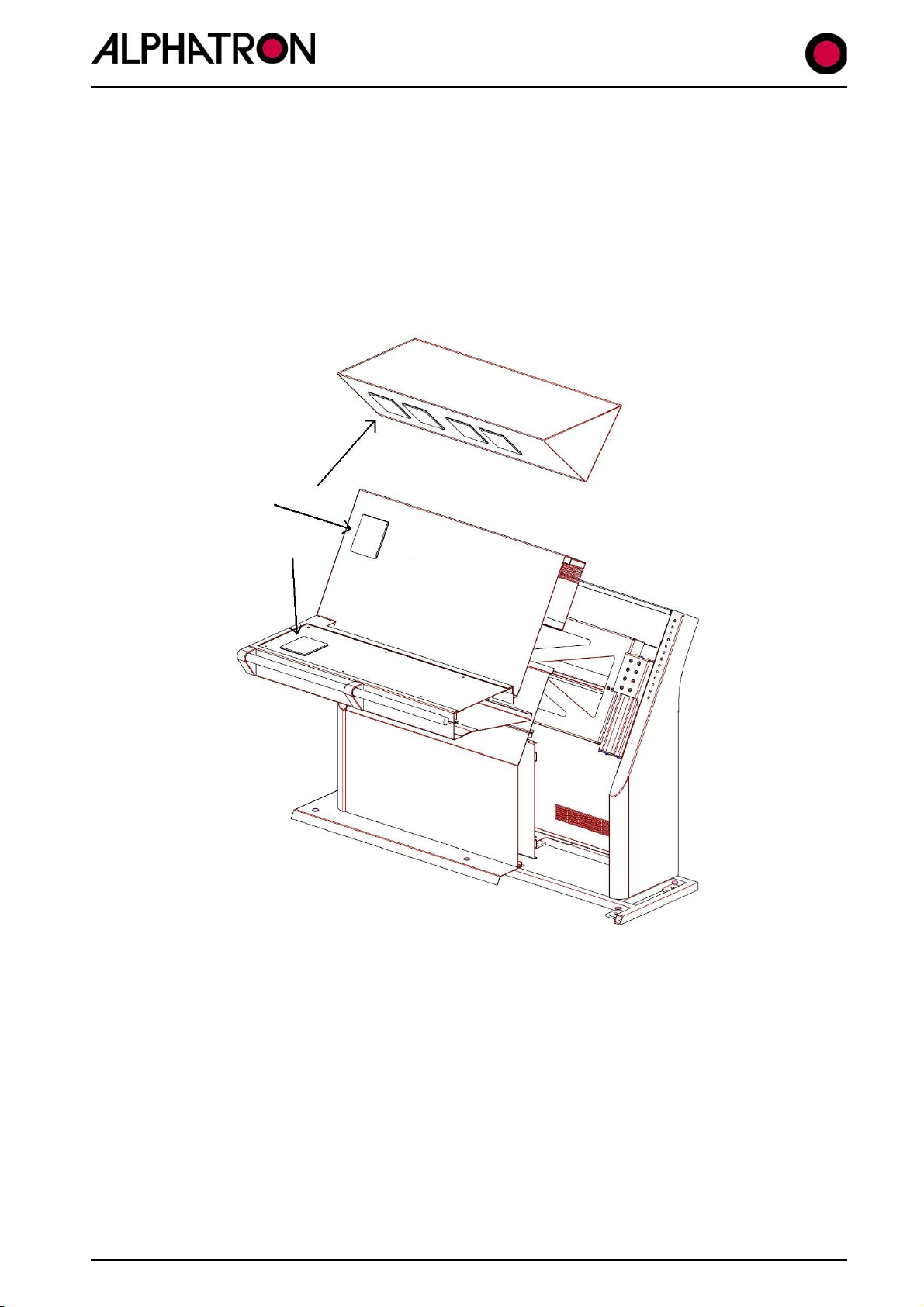
3.2.1 Flush mounting the ALPHACALL MF...............................................................7
3.2.2 ALPHACALL MF surface mounted ..................................................................9
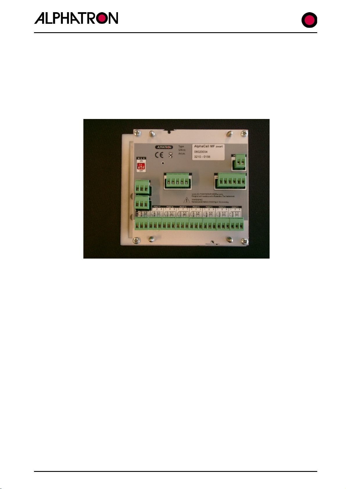
3.3 Connecting the ALPHACALL MF..........................................................................10
3.3.1 Terminating the cables...................................................................................11
3.3.2 Connecting the power supply.........................................................................12
3.3.3 Connecting the microphone and the foot switch............................................12
3.3.4 Connecting the substations............................................................................13
3.3.5 Connecting the external speaker...................................................................13
3.3.6 Connecting the external signalling device......................................................14
4OPERATING THE ALPHACALL MF............................................................................15
4.1 Buttons..................................................................................................................15
4.1.1 Switching the ALPHACALL MF on/off............................................................15
4.1.2 Dimming the ALPHACALL MF.......................................................................15
4.1.3 Setting the ALPHACALL MF outgoing and incoming volume ........................15
4.1.4 (De)selecting the substations.........................................................................15
4.1.5 Answering a call from one of the substations.................................................16
4.1.6 Giving a call signal.........................................................................................16
4.1.7 Making a call..................................................................................................16
4.1.8 Calling several substations simultaneously....................................................16
4.1.9 Setting the colour of the backlight..................................................................16
5TROUBLESHOOTING.................................................................................................17
6TECHNICAL SPECIFICATIONS..................................................................................17
7TECHNICAL SUPPORT ..............................................................................................17
8ALPHATRON Dealers (Authorized) .............................................................................18
9Appendix 1: Mounting frame ........................................................................................19
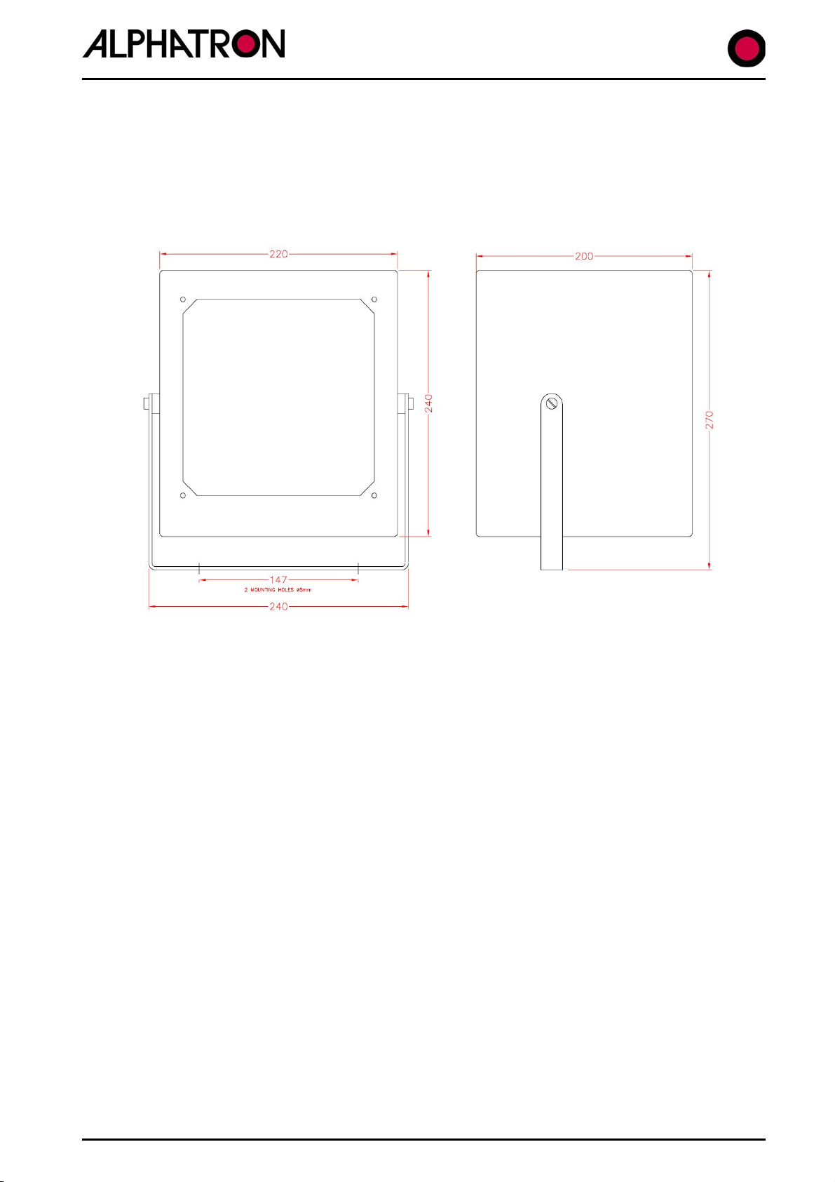
10 Appendix 2: Instrument dimensions..........................................................................20
Appendix 3: Complete connection diagram.........................................................................21
11 NOTES:....................................................................................................................22

ALPHACALL MF manual version 1.0 Page 3 of 22
ALPHACALL MF
Important!
Do not make changes to the instrument in whatever way without the written
approval of ALPHATRON MARINE, otherwise the guarantee will lapse.
Please read the manual thoroughly before installing and/or using the
instrument.
Terms of delivery: The general sales and delivery conditions for the metal and
electrotechnical industry, as filed at the Registry of the District Court of The
Hague on 21 August 1991, apply to all our deliveries. Listed in the Commercial
Register of the Chamber of Commerce in Rotterdam, under file number 182635.
Guarantee period: For Alphatron equipment, 1 year with respect to material
and/or construction errors; excluding travel and accommodation expenses and
additional sea trials. Unless agreed otherwise.
Nothing from this manual may be copied and/or published by means of print, photocopy, microfilm or in whatever form whatsoever,
without the prior written permission of Alphatron.
Although this manual has been created with the greatest possible care, Alphatron does not accept any liability for the consequences of
any inaccuracies it contains.

ALPHACALL MF manual version 1.0 Page 4 of 22
ALPHACALL MF
1VERSION CONTROL
Revision number Description Date
V1.0 document drawn up 03/06/08

ALPHACALL MF manual version 1.0 Page 5 of 22
ALPHACALL MF
2INTRODUCTION
The ALPHACALL MF is one of the products from the ALPHALINE MF product line. Because the
ALPHACALL MF allows the connection of up to 10 substations, it can be used on many different
types of ship.
When designing the ALPHACALL MF, careful attention was paid to the production of sound that
is as crisp and clear as possible. However, this will depend on the location of the substations
and the location of the gooseneck microphone if there is a lot of ambient noise near the main
unit.
The ALPHACALL MF intercom consists of a main unit, normally installed in the wheel house, to
which substations are connected that can be located outside, inside, in the engine room, etc. A
gooseneck microphone equipped with a foot switch is connected to the ALPHACALL MF.
The ALPHACALL MF works as a two-way command and intercom system. Communication occurs
between the ALPHACALL MF operating unit and the substations that are connected to it,
therefore not between the substations.
Substations that do not have the call facility are connected to the ALPHACALL MF using three-
core cables, substations that do have the call option are connected using four-core cables.
Meaning that in general it is easy to replace an existing intercom. The substations that have an
additional signal unit need a six-core cable.
2.1 Options
Optionally, the following peripheral equipment is available:
Gooseneck microphone
Foot switch
External loudspeaker for the main unit
Substation for indoor use in the living accommodation, including call and talk button
Substation for use in the engine room, with headphone connection
Loudspeaker
Substation with call button for location outdoors, in combination with loudspeaker
Engine room telephone
Bridge operation
Amplifier
Substation for mobile loudspeaker
Connecting box for headphones connection
Substation for use in the engine room, with headphone connection, external speaker and
on/off switch
Cabin units
Outdoor units
Engine room unit
Foot switch & Gooseneck
Main unit

ALPHACALL MF manual version 1.0 Page 6 of 22
ALPHACALL MF
3INSTALLATION
3.1 Materials supplied
The ALPHACALL MF hardware consists of the following parts:
Mounting frame
ALPHACALL MF main unit
10x Substation connector
1x Mic, PTT, speaker connector
1x External call connector
1x Power connector
Figure 1: The complete hardware of the ALPHACALL MF

ALPHACALL MF manual version 1.0 Page 7 of 22
ALPHACALL MF
3.2 Installing the ALPHACALL MF
The ALPHACALL MF can be installed in a number of different ways. The instrument can be flush
mounted and there is also a surface mounting option.
3.2.1 Flush mounting the ALPHACALL MF
De ALPHACALL MF can be installed horizontally, vertically as well as at an angle. The possible
positions are shown in Figure 2.
Figure 2: Possible flush mounting positions
To be able to install the ALPHACALL MF, first the mounting frame must be fitted. To do so,
an opening must be made in the console or overhead console that has the dimensions of the
mounting frame. The dimensions of the mounting frame are given in the appendix of this
manual.

ALPHACALL MF manual version 1.0 Page 8 of 22
ALPHACALL MF
Figure 3: Mounting frame
When the opening for the mounting frame has been made, the mounting frame can be installed
in it. The mounting frame must be attached using four screws through the intended holes.
These holes are indicated with arrows in Figure 3. After the mounting frame has been installed,
the ALPHACALL MF can be pressed into it. The instrument will be kept in position by a
click/spring system.

ALPHACALL MF manual version 1.0 Page 9 of 22
ALPHACALL MF
3.2.2 ALPHACALL MF surface mounted
For surface mounting the ALPHACALL MF, an additional DIN 144 housing is required. This
housing is not supplied as standard.
Figure 4: Surface mounted housing MF line

ALPHACALL MF manual version 1.0 Page 10 of 22
ALPHACALL MF
3.3 Connecting the ALPHACALL MF
The ALPHACALL MF has in total 13 connectors at the back of the instrument. The various
connectors and their functions are given below.
-Connector 1 = power supply (24VDC)
-Connector 2 = Ext. speaker, microphone and foot switch
-Connector 3 = External call indication
-Connector 4-13 = Substations 1 through 10
Figure 5: ALPHACALL MF connectors

ALPHACALL MF manual version 1.0 Page 11 of 22
ALPHACALL MF
3.3.1 Terminating the cables
The ALPHACALL MF must be connected in accordance with the instructions in the Appendix.
When designing the ALPHACALL MF, careful attention has been given to the sound quality.
To guarantee this quality in the installed system, here are some recommendations regarding
the grounding of the system:
Prevent ground loops, make one central ground point.
The main unit must be grounded.
The shielding of the power supply cable must be correctly grounded.
In addition, connect unused cores of the cables to ground.
The shielding of the cables to the substations must be correctly grounded.
Ensure that the cable of the gooseneck is separated from other cables, to prevent cross-talk
and/or acoustic feedback. Note that the ground of the microphone is not connected to the
ship's mass, but to the minus connection of the microphone input.
With respect to the cables to use, the following:
For the majority of substations, a three-core shielded cable is sufficient.
Preferably use twisted pair shielded cables for the substations.
For substations that have a provision for an additional signal indication, at least a five-core
shielded cable must be used. See the Appendix for an overview of the substations.
Install the cable connections between the devices in accordance with the Appendix.
If not stated differently, shielded cables with flexible cores must be used with a minimum
core diameter of 0.5mm².
The cabling must not run for long distances next to UTTP or antenna cables that carry high
currents.
For the instrument to operate correctly, it is essential that all of the cables are terminated
correctly.

ALPHACALL MF manual version 1.0 Page 12 of 22
ALPHACALL MF
3.3.2 Connecting the power supply
The ALPHACALL MF must be connected to a 22VDC to 32VDC power supply that can supply at
least 2 ampere. Connector 1 in Figure 6 is the power connector. The polarity of the power
connectors is shown on the sticker on the back of the instrument. The maximum core thickness
that can be connected is 2.5mm². The complete connection diagram of the ALPHACALL MF is
included in the Appendix of this manual.
Figure 6: Connecting the power supply
3.3.3 Connecting the microphone and the foot switch
The ALPHACALL MF has no internal microphone and must therefore be connected to an external
microphone (gooseneck). To prevent interference, the shielding of the microphone must be
connected to the - pole of the microphone input. The talk button (foot switch) connection is
located next to the microphone connection. The complete connection diagram of the ALPHACALL
MF is included in the Appendix of this manual.
Figure 7: Connecting the microphone and the foot switch

ALPHACALL MF manual version 1.0 Page 13 of 22
ALPHACALL MF
3.3.4 Connecting the substations
Up to 10 substations can be connected to the ALPHACALL MF. The outputs for substations 7
through 10 have the option of generating an external signal at the substation, for instance, a
flashing light, see the relevant section of this document. The intercom must be connected to
the substation using a three-core cable. One of the cores is the call signal from the substation
to the intercom, another core is the audio signal and the last core is common. The complete
connection diagram of the ALPHACALL MF is included in the Appendix of this manual.
Figure 8: Connecting the substations
3.3.5 Connecting the external speaker
The ALPHACALL MF has a connection for an external speaker, this is located next to the
microphone connection. The complete connection diagram of the ALPHACALL MF is included in
the Appendix of this manual.
Figure 9: Connecting the external speaker

ALPHACALL MF manual version 1.0 Page 14 of 22
ALPHACALL MF
3.3.6 Connecting the external signalling device
The outputs for the substations 7 through 10 have the option of generating an external signal at
the substation for instance by means of a flashing light. The output signal of these connections
is 12V and max. 10mA. The complete connection diagram of the ALPHACALL MF is included in
the Appendix of this manual.
Figure 6: Connecting the external signalling device

ALPHACALL MF manual version 1.0 Page 15 of 22
ALPHACALL MF
4OPERATING THE ALPHACALL MF
This Chapter explains how to operate the ALPHACALL MF.
Figure 7: Operating the ALPHACALL MF
4.1 Buttons
The instrument is operated using buttons on its front.
4.1.1 Switching the ALPHACALL MF on/off
To switch on the ALPHACALL MF, press the ‘on/off’ button briefly. The instrument will
immediately switch on. To switch off the instrument, press and hold the ‘on/off’ button
somewhat longer.
4.1.2 Dimming the ALPHACALL MF
To change the backlight of the ALPHACALL MF, the ‘dim’ button must be pressed briefly and
repeatedly. The lighting will change in a cycle from minimum to maximum.
4.1.3 Setting the ALPHACALL MF outgoing and incoming volume
Use the ‘<’ and ‘>’ buttons to separately adjust the outgoing and incoming volume of the
intercom.
4.1.4 (De)selecting the substations
Press one of the buttons 1 through 10 briefly to select a substation, the indicator for this
substation will turn green. As long as the indicator is green, a conversation can be held with this
substation. Press the button concerned somewhat longer to deselect the substation.

ALPHACALL MF manual version 1.0 Page 16 of 22
ALPHACALL MF
4.1.5 Answering a call from one of the substations
If a call is made from one of the substations, the indicator of the substation concerned will turn
red. Select the substation by briefly pressing the button (1 through 10) that corresponds to
substation, the indicator for this substation will turn green. As long as the indicator is green, a
conversation can be held with this substation. Press the button concerned somewhat longer to
deselect the substation.
4.1.6 Giving a call signal
First select one of the substations, its indicator will turn green. Then press the ‘signal’ button to
generate an audible signal.
4.1.7 Making a call
First select one of the substations, its indicator will turn green. Press the ‘talk’ button to talk to
the substation, when the ‘talk’ button is not pressed, the intercom is in listening mode. Note
that a private function is built in to certain substations, as a result the ‘talk’ button at the
station concerned must be kept pressed to be able to talk using the intercom.
4.1.8 Calling several substations simultaneously
If several substations must be addressed simultaneously, they must be selected. The indicators
of the selected substations will turn green.
4.1.9 Setting the colour of the backlight
On the back of the instrument, there are three dip switches that can be used to set the colour of
the backlight of the buttons. The text above the switches corresponds to the following colours:
W=white, G=green and R=red.
Figure 8: Setting the backlight colour

ALPHACALL MF manual version 1.0 Page 17 of 22
ALPHACALL MF
5TROUBLESHOOTING
6TECHNICAL SPECIFICATIONS
Electrical:
Parameter Value Comments
Operating voltage 22-30 Volts DC voltage
Power consumption 30mA turned off
Max. 2A turned on
Reverse battery protection Yes
Max number of substations 10
Substations with ext. signal 4 (substation 1-4), 12V max 10mA
Built-in speaker Yes
External speaker Yes, optional (8Ω/4-15W)
Frequency range Better then 200-6000Hz(-3dB)
Output power 15W, max. 10W per line
EMC Yes
EMC approved IEC60945
Mechanical:
Parameter Value Comments
Size 161x181x123mm
Weight 1.5 Kg
IP IP22 Front side
Environmental:
Parameter Value Comments
Operating temperature 0°C to +50°C
Storage temperature -10°C to +50°C
7TECHNICAL SUPPORT
If you require technical support for this ALPHACALL MF, please contact:
Alphatron Marine BV
Schaardijk 23
3063NH, Rotterdam
P.O. Box 21003
The Netherlands
Tel: 0031(0)10 4534000
Fax: 0031(0)10 4529214
www.alphatronmarine.com

ALPHACALL MF manual version 1.0 Page 18 of 22
ALPHACALL MF
8ALPHATRON Dealers (Authorized)
THE NETHERLANDS BELGIUM
Alphatron Marine BV Alphatron Marine BVBA
Schaardijk 23 Vaartkaai 12
3063 NH ROTTERDAM B – 2170 MERKSEM
Tel. + 31 (0)10 453 40 00 Tel. + 32 3 364 68652
Fax. + 31 (0)10 452 92 14 Internet: www.alphatronmarine.com
Internet: www.alphatronmarine.com E-mail : servicebe@alphatronmarine.com
FRANCE NORWAY
Etna ProNav AS
Les Hautes Vallees Fiskarvik Maritime Senter
Route de mondvilliers 76930 4370 EGERSUND
OCTEVILLE-SUR-MER-CEDEX Tel. + 47 514 94 300
Tel. + 33 2 355 460 60 Fax.+ 47 514 92 100
Fax. + 33 2 355 460 59 Internet: www.pronav.no
Internet: www.etna.fr E-mail : mail@pronav.no
SPAIN SINGAPORE
Crame Navtronics Pte. ltd.
C/Lanzarote 14 76 Playfair Road
28700 #06-05 LHK 2 BUILDING
San Sebastian de los Reyes SINGAPORE 367996
MADRID Tel.: + 65 38 32 788
Tel. + 34 91 658 65 08 Fax.:+ 65 38 32 188
Fax. + 34 91 654 96 44 Internet : www.esi-online.com.sg
UNITED KINGDOM INDIA
Selex Communications Ltd Elektronik Lab
Marconi House R/13 Navroz Baug
New Street Lalbaug MUMBAI 400012
CHELMSFORD Tel. + 91 22 247 151 15
ESSEX CM1 1PL Fax. + 91 22 247 104 44
UNITED KINGDOM Internet: www.elektroniklab.com
Fax.+ 44 (0) 1245 27 56 89
Internet: www.selex-comms.com
UNITED ARAB EMIRATES
Elcome International L.L.C.
Al Jadaf Dockyard – DY159
P.O. Box 1788
DUBAI
UNITED ARAB EMIRATES
Tel. + 971 4 4049100
Fax. + 971 4 049200
Internet: www.elcome.ae
E-mail: info@elcome.ae

ALPHACALL MF manual version 1.0 Page 19 of 22
ALPHACALL MF
9Appendix 1: Mounting frame

ALPHACALL MF manual version 1.0 Page 20 of 22
ALPHACALL MF
10 Appendix 2: Instrument dimensions
Table of contents