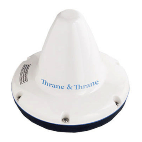
TT-3000E mini-C GMDSS System Installation Manual
List of Figures:
Figure 1 TT-3000E mini-C GMDSS System overview............ 14
Figure 3 TT-3616C GMDSS Interconnection Box .................. 16
Figure 4 AP5042 Inmarsat-C Alarm Panel............................. 17
Figure 5 TT-3042C Remote Alarm/Distress Box ................... 18
Figure 6 AP4365 Alarm Panel............................................... 19
Figure 7 TT-3606E Message Terminal.................................. 21
Figure 8 TT-3608A Hard Copy Printer.................................. 22
Figure 9 N163S Power Supply.............................................. 23
Figure 10 Page 1 of the Service Activation Registration Form27
Figure 11 1" Pole mounting.................................................. 34
Figure 12 Vertical and Horizontal adjustable pole mount..... 34
Figure 13 Viewing Angle to the Horizon............................... 36
Figure 14 Mounting near pole or funnel (overhead view) .... 36
Figure 15 Outside view of TT-3616C.................................... 40
Figure 16 Inside view of TT-3616C....................................... 40
Figure 17 Recommended free space around TT-3616C........ 41
Figure 18 Drill template. All measures in mm...................... 42
Figure 19 Grounding using 4mm2wire. ............................... 43
Figure 21 Power cable connections. .................................... 45
Figure 22 Transceiver cable preparation............................. 46
Figure 23 Preparation for grounding of the cable screen..... 47
Figure 24 Fixation of the transceiver cable in TT-3616C....... 48
Figure 25 Mounting of transceiver cable wires. ................... 49
Figure 26 RS232 cable connection. ...................................... 50
Figure 28 Preparation of cable for alarm panels .................. 51
Figure 29 Mounting of cables for alarm panels .................... 52
Figure 30 Location of connector J302 ................................... 53
Figure 31 Alarm panels on RS485 bus – T-Port wiring. ......... 53
Figure 32 Alarm panels on RS485 bus – direct wiring........... 54
Figure 33 Powering AP5042 directly from TT-3616C............ 55
Figure 35 TT-3606E Message Terminal................................ 57
Figure 36 TT-3606E Rear Connectors................................... 58
Figure 37 Mounting holes for TT-3606E................................ 60
Figure 38 TT-3606E Mounting Bracket ................................. 61
Figure 39 TT-3608A Hard copy printer................................. 62
Figure 40 TT-3608A Paper Roll Stand................................... 63
Figure 41 Mounting holes for TT-3608A (Unit is mm)............ 64
Figure 42 AP5042 Inmarsat-C Alarm Panel........................... 65
8/97


