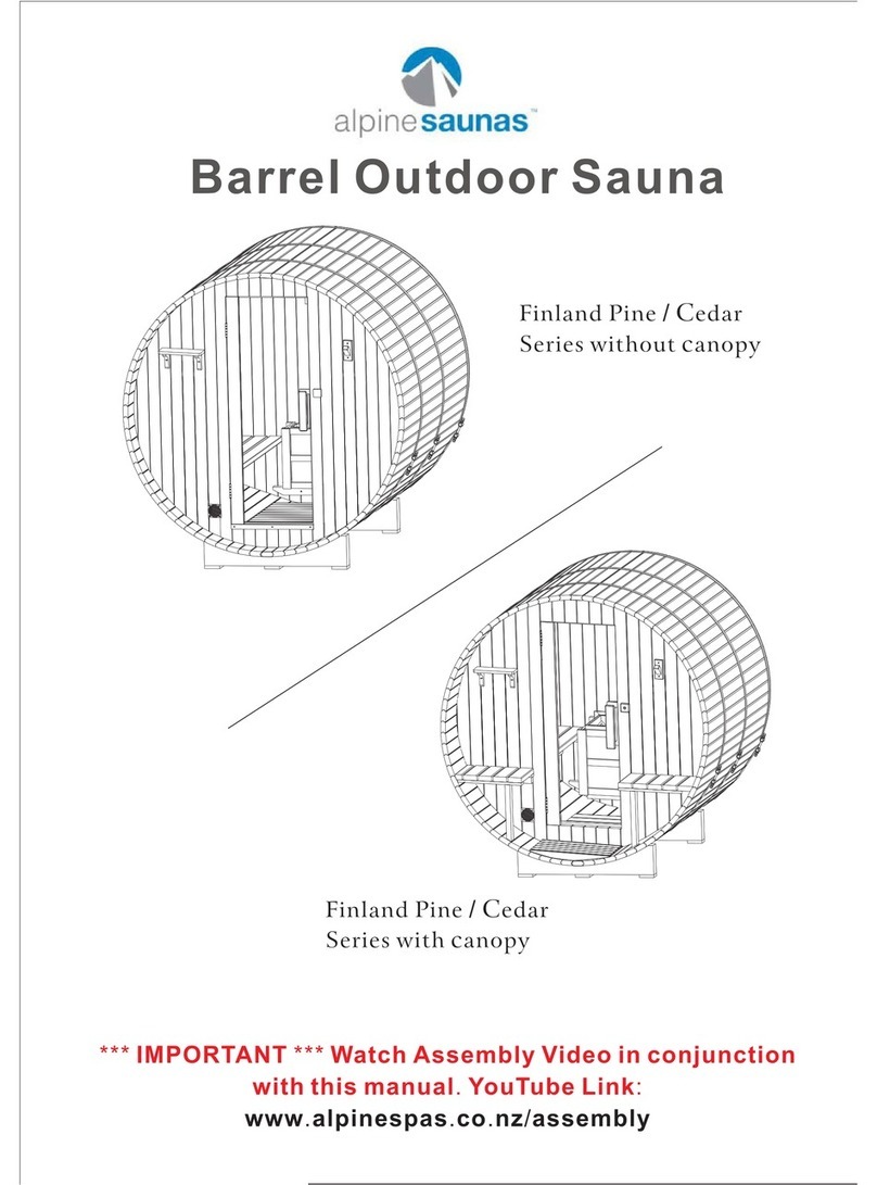
Alpine Saunas Outdoor Barrel Sauna User manual

CEDAR BARREL SAUNA
Installation Manual

Instructions before assembly
1. Ensure the foundation is level and can withstand the weight of the barrel sauna
without subsiding.
2. The Sauna Heater and Light require installation from a certified electrician.
Tools
Screw drivers set, power drill set, measuring tape, level, mallet, socket set.
Parts list
1. Regular Staves: 62pcs (31pcs for the right side, 31pcs for the left side). 15pcs of
the right side without wax oil for the top part. 16pcs of the right side with wax oil
for the bottom part. 15pcs of the left side without wax oil for the top part. 16pcs
of the left side with wax oil for the bottom part.
2. Top final stave: 2pcs (two smaller size staves. only 1pc is required).
3. Bottom stave: 1pc (with 2 holes)
4. Front and rear edging----7pcs/set * 2
5. Front panel part 1: 1pc
6. Front Panel part 2 (glass door): 1pc
7. Front Panel part 3: 1pc
8. Back panel part 1: 1pcs
9. Back Panel Part 2: 1pc
10. Back Panel Part 3: 1pc
11. Panel Set Securing Piece: 4pcs
12. Cradle Base----3pcs
13. Inside floor panel: 2pcs
14. Outside floor panel: 1pc
15. Glass door +door handle + door hinge —1set
16. Outside bench & bench leg –2sets
17. Inside bench & bench leg ----2sets

18. Outside Bench support beam: 2pcs
19. Inside bench support beam: 2pcs
20. Triangle wooden piece ---2pcs
21. Heater Fence --1set
22. backrest --- 4pcs
23. Door locker unit ---1set
24. Towel rack ---1 set
25. Magazine reack ----1set
26. Cup holder ----1set
27. 4.5KW stove heater –1pc
28. Water bucket –1pc, Sand Timer -1pc , Ladle -1pc
29. Hygrometer –1pc
30. Sauna stone –1 box
31. Bitumen roof ---1set
32. Steel strip ----3pcs
33. Screws - 1 bag
FIRST CONSIDERATIONS
When you begin the initial layout for assembly, it is very important to check your
floor or deck to see if it is level. Most garage floors and decks are sloped for drainage.
If this is the case in your installation, it is suggested that you use shims to make the
sauna level. Failure to do this can result in uneven panels, poor fit and or poor
function of your sauna.

OUTDOOR INSTALLATION RECOMMENDATIONS
Take caution to prevent the wind from catching and breaking the glass door.
NOTE: While your Barrel Sauna is designed for outdoor use, it is important to build
the sauna in accordance with these instructions to minimize water seepage into the
sauna. Properly installed, water will not drip into the sauna. However, over time
water may seep between the staves due to the porous nature of softwood. This will
not hurt the sauna and it should evaporate once the sauna heater is turned on. Light
sanding may be required to reduce the appearance of water stains.
STAVE LAYOUT
LIGHT CABLE
IMPORTANT! –Should you wish to use the light cable channel provided within the
front panel part 3, wiring must be fed through the channel BEFORE fixing the three
front panels together. See page #7
(Cable not included)

INSTALLATION INSTRUCTIONS
1. Assemble the base using the 3x ‘Cradle Base’ supports and 1x ‘Bottom Stave’
(oiled with two drain holes). Fit the bottom stave into the cradle bases using the
provided grooves on the oiled side of the stave (the stave should hang over the
front cradle further than it does over the back cradle). Screw the bottom stave
into the cradle base supports using 3x ‘4*40mm’ screws. Note that there are no
predrilled holes.
2. Place 7x ‘Staves - Regular Oiled’ on either of the secured bottom stave. Use a
rubber mallet to gently tap the staves together. Use 42x ‘4*40mm screws’to fix
the staves across the ‘cradle bases’. Pre-drill holes if required.

3. Assemble the ‘Back Panel Parts 1, 2 & 3’ flat on ground with non-oiled side &
bench supports right side up.
Secure the back panel assembly together using 4x ‘5*70mm Screws’ into the
pre-drilled locations below. Screw the 2x ‘Panel Set Securing Pieces’ onto the top
and bottom of the back panel assembly using 22x ‘4*40mm Screws’.
Back Panel Part 2
Rear Middle Panel
Back Panel Part 1&3
Rear Side Panel Left & Right
(Half crescent with no vents or holes.)
Panel Set Securing Pieces

4. Lay the ‘Front Panel Parts 1, 2 & 3’ flat on the ground with non-oiled side right
side up.
Before securing the front panels together, consideration must be made for the
wiring of the Lamp / Sauna light. The included lamp does not come with wiring or a
switch, these must be provided and installed via an electrician. A wire channel is
provided in the ‘Front Panel Part 3’ as shown below.
Front Panel Part 1
Left side Panel
(Half crescent with no vents or holes.)
Front Panel Part 2
Middle Glass Door
Front Panel Part 3
Right Side Panel
(Half crescent with vent hole at bottom,
serial plate at top)
Using a pencil,
mark the bottom
of the’ Front
Panel Part 3’
(within the red
circle shown) as
to where the
channel sits. This
info will be used
to line up a
drilling spot on
the stave below.

The cable needs to exit out through the bottom of the Sauna. To achieve this, the
front panels should be slotted together but NOT screwed and then placed into
position on the staves (please employ help keeping the front wall upright and
secure). Ensure the front wall is sitting level. Using the first pencil indication mark as
a guide, mark a second point on the ‘regular stave’ that lines up accordingly. This will
give an indication as to which ‘Regular Stave’ will be need to be drilled through.
Remove the front wall. Using the second pencil indication mark as a guide, drill a
hole (size suitable for light cable provided by electrician) within the groove on the
correct stave down through the stave to underneath the sauna.
Pencil Indication 1
Pencil Indication 2
Drill down inside groove.

5. Insert the Light Cable through the Light Hole and down through the provided
cable channel in the ‘Front Panel Part 3’
6. Ensure the light cable sits correctly in the channel and Secure the ‘Front Panel
Parts’ together using 5x ‘5*70mm Screws’ into the locations below (circled red).
Install the 2x ‘Panel Set Securing Pieces’ using 22x ‘4*40mm Screws’.
Light Hole
Cable Channel

7. Install 9x ‘Regular Staves - Oiled’ on each side of the barrel.
(See page 3 for diagram on staves).
Use 36x ‘4*40mm screws’to fix the 18pcs staves to the front & back panel.
8. Install 15x ‘Regular Staves –Non-Oiled’ on each side forwards the top but DO
NOT fasten with screws yet. (See page 3 for diagram on staves)
Use a rubber mallet to gently tighten up the staves.
9. The remaining gap will be filled with the ‘Top Final Stave’ which is available in
two sizes. Due to natural swelling/shrinking of the cedar wood, one piece is
likely to fit better than the other. Choose the one that fits best.
Place the stave into the gap by lifting the surrounding pieces upwards to create a
small arch. Gently push down and use a rubber mallet lightly to tap into place.
After the top piece is correctly installed, fix the remaining staves with ‘4*40mm
screws’.

10.Install the ‘glass door’into the door frame using the ‘door hinges’ using 2x
‘6*55mm, flat head screws’.
Install the ‘door handle’.
Install the ‘door locker unit’ with 2x ‘3*25mm screws’
11. Install the Hook 4x ‘3*30mm Screws’
Install the Cup holder using 2x ‘4*40 Screws’

12. See separate Steel strip assembly Document.
Caution! Sharp Edges! Protective gloves are advised.

13. Install the benches inside in the barrel. Place the long benches onto the sides of
the barrel using the supports at the front and back panels. In the center on the
benchs underneath, install the 20cm ‘Inside bench support beam’ onto the side of
the barrel wall using 2x ‘4*40mm Screws’. Then screw the bench from the topside
down into the support beams.
Install the bench leg supports on each side and secure with 2x ‘4*40mm Screws’.

14. Outside Bench Seat Assembly
A. Fix the ‘Outside bench support beam’ (30cm) to the side of the barrel level with
the corresponding support on the front wall. Secure with 2x ‘4*40mm’ screws.
B. Place the bench leg support into the outside bench seat.

C. Place the bench seat and leg support onto the support beams. Secure the leg
support into the barrel using 2x ‘4*40mm Screws’
15. Place the 3pcs floors and fix them with screws.
16. Heater Fence Assembly: 4pcs 6*35mm flathead screws needed.

17. Heater Assembly –please refer to the manufacturer’s instructions. After heater
installation, pls fix the heater fence to the wall with ‘4x 4*40mm’sharpened head
screws.
18. Install the lamp & lamp holder.
19. Install bitumen roof
Bitumen roof installation
Install the triangle wood piece to the barrel with 3*30mm screws at both sides.
Install the shingles from bottom to the top, from both sides at the same time.
3*14mm screws needed.

Example Left Side
Row 1: G2 + A + A
Row 3: G1 + A + A


20.Install the ‘Front and Back Edging’ using 2x ‘3*30mm screws’ per piece. These are
numbered accordingly.
Table of contents
Other Alpine Saunas Plumbing Product manuals
Popular Plumbing Product manuals by other brands

Costway
Costway KC52633US user manual

Almost Heaven Saunas
Almost Heaven Saunas TIMBERLINE Assembling instructions

RUVATI
RUVATI epiGranite Series installation guide

The Splash Lab
The Splash Lab Aerofoil Instruction guide

Hans Grohe
Hans Grohe AXOR Massaud 18013000 Instructions for use/assembly instructions

Roper
Roper G12-436 owner's manual