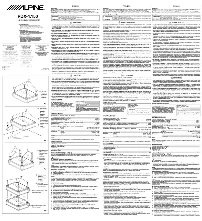
manuals.online logo
Brands
  1. Home
  2. •
  3. Brands
  4. •
  5. Alpine
  6. •
  7. Amplifier
  8. •
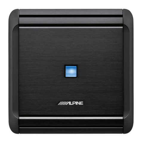
  9. Alpine MRV-F400 User manual

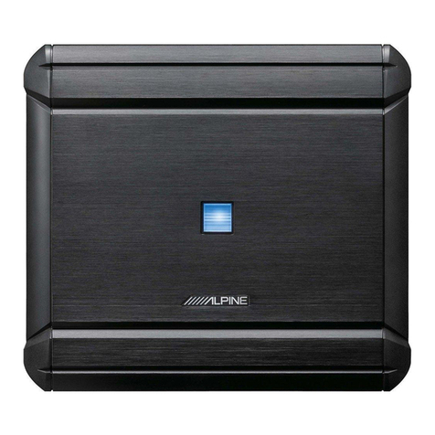
Alpine MRV-F400 User manual

OWNER’S
MANUAL/BEDIENUNGSANLEITUNG/
MANUEL
DU
PROPRIETAIRE/MANUALE
DEL
PROPRIETARIO/
MANUAL
DEL
PROPIETARIO/BRUKSANVISNING
MRV-F400
4/3/2
Channel
Power
Amplifier
romney
LB)
aie
tS
towowa,
ST
12
OFF
WP
OP
MMAP
INE
yrur Moot
Loreen
4r2
CHANNEL
U
CHANNEL
172.
POWEH
AMPLIFIER
MRV-€400
@
=
Fig.
1/Abb.
1
SWITCHES
AND
TERMINALS/SCHALT
NSCHLUSSE/COMMUTATEURS
ET
BORNES/INTERRUTTORI
E
TERMINALIANTERRUPTORES
Y
TERMINALES/OMKOPPLARE
OCH
ANSLUTNINGAR
@
Fig.
2/Abb.
2
INSTALLATION/EINBAU/INSTALLATION/INSTALLAZIONE/INSTA\
@
>
Fig
BIADB.
B28
tee
eed
hoo
bese
ene
ccc
tess
ba
basd
ncopsthcseste
vend
sven
sbtpvedivcvasibaviee
tdteaartch
sued?
stones
eee
siyuacrutean
eat
4
CONNECTIONS/ANSCHLUSSE/CONNEXIONS/COLLEGAMENTI/CONEXIONES/ANSLUTNINGAR
@
=
Fig.
4-6/Abb.
4-6
TYPICAL
SYSTEM
CONNECTIONS/TYPISCHE
SY:
CHLUSSE/CONNEXIONS
TYPIQUES
DU
SYSTEME/
SISTEMI
TIPICI
Di
COLLEGAMENTO/SISTEMA
TIPICO
DE
CONEXIONES/TYPISKA
SYSTEMANSLUTNINGAR
“ENGLISH"
INTRODUCTION
..
FEATURES.
SWITCHES
AND
TERMINALS
..
PRECAUTIONS
......
eee
a
10
CONNECTIONS
...
INSTALLATION
....
SWITCH
SETTINGS
.
SPECIFICATIONS
....
“DEUTSCH"
EINFUHRUNG
MERKMALE
....
SCHALTER
UND
ANSCHLUSSE
..
VORSICHTSMASSNAHMEN
.
ANSCHLUSSE
EINBAU
SCHALTER-EINSTELLUNG
...
TECHNISCHE
DATEN
"FRANCAIS"
INTRODUCTION
..........
CARACTERISTIQUES
.
COMMUTATEURS
ET
BORNES
.........
PRECAUTIONS
..
CONNEXIONS
.
INSTALLATION
..
REGLAGE
DES
COMMUTATEURS
.
SPECIFICATIONS
"ITALIANO"
INTERRUTTORI
E
TERMINALI
PRECAUZIONI
COLLEGAMENTI
.
INSTALLAZIONE
....
REGOLAZIONE
DEGLI
INTERRUTTORN
Shee
asic
ieeaiiaw
none,
56,
57
SRECIFICAZION
o.55
cvcitd
eee,
ercshaenbaseanciee
ante
eace,
58
"ESPANOL"
INTRODUCCION
CARACTERISTICAS
....
INTERRUPTORES
Y
TERMINALES
..
PRECAUCIONES
CONEXIONES
INSTALACION
..
AJUSTE
DE
INTERRUPTORES
..
ESPECIFICACIONES
"SVENSKA"
INTRODUKTION
...
EGENSKAPER
........
OMKOPPLARE
OCH
ANSLUTNING
FORSIKTIGHETSATGARDER
.......0......
ANSLUTNINGAR
..
INSTALLATION
OMKOPPLARPOSITIONER
SPECIFIKATIONER
@
CHARACTERISTIC
CURVES/CHARAKTERISTISCHE
ENTZERRERKURVEN/COURBES
CARACTERISTIQUES/
CURVE
CARATTERISTICHE/CURVAS
CARACTERISTICAS/FREKVENSKURVOR
@
SYSTEM
CHARTS/SYSTEMAUFBAU/DIAGRAMMES
DU
SYSTEME/DISPOSIZIONI
DEL
SISTEMA/
DIAGRAMAS
DEL
SISTEMA/SYSTEM-OVERSIKT
...........
rowern—C_)
MUALPRE
-arar2
CHANEL
OWEN
AMPLIFIER
MRV-F400
14
15
16
eh
2
2005)
Fig.
1/Abb.
1
@
Ground
Lead
*
g
®
Chassis
@
Holes
Fig.
2/Abb.
2
®
Speaker
Output
Terminals
©
RCA
Output
Jacks
@
PCA
Input
Jacks
SUV
uy
ye
ie
fu
}——@
Insulation
Tube
J
nf
4)
Battery
Lead
(Yellow)
@
Remote
Turn-On
Lead
‘)
(Blue/White)
pee
Sg
Oe
ake
©
Ground
Lead
(Black)
§
ame
pe
ed
Fig.
3/Abb.
3
eee
ay
4
4-Channel
System/4-Kanal-System/Systéme
a
4
canaux/Sistema
a
4
canali/
Sistema
de
4
canales/4-kanalssystem
@
Rear
Speakers
@
Front
Speakers
®R OL
®R
OL
Battery
Lead
@
fc?
Ground
Lead
©
bendy
Ul
Head
Unit
with
Pre-Amp
Outputs
ii
oo
BE
=
of)
5p
ff
myst
>
_.
fh
<a
Lb
4Ukm
amg
=<
Extension
Cable
(Sold
Separately)
MaRv-F400.
T
MODE
|@
CROSSOVER
MODE
SELECTOR
SWITCH
|
SELECTOR
SWITCH
yt
1(MONQ)
ST
142
INPUT
MODE
er
3(MONO)ST
3+4
INPUT
MODE
Fig.
4/Abb.
4
3-Channel
System/3-Kanal-System/Systéme
a
3
canaux/Sistema
a
3
canali/
Sistema
de
3
canales/3-kanalssystem
SUBWOOFER
_
Front
Speakers
(High-Pass)
@
®
(Low-Pass)
@R
OL
Battery
Lead
@
Ground
Lead
@
Cc)
CY
{ir
Seon
BG
Lert
rant
ert
py
PH
(ue
pn
ite
[
ese
Head
Unit
with
1
Set
of
Pre-Outs
@
Settings
(Front
Side)
402
channe.
PGWER
Aweuitier
wV-F
400
@
INPUT
MODE
=
|@
CROSSOVER
MODE
SELECTOR
SWITCH
|
SELECTOR
SWITCH
4
(MONO)
INPUT
—T
Th
3(MONO)ST
3+4
OFF
HP
LP
INPUT
MODE
FILTER
Fig.
5/Abb..5
2-Channel
System
(Full
Range)/2-Kanal-System
(gesamtes
Frequenzband)/
Systéme
a
2
canaux
(Large
Bande)/Sistema
a
2
canali
(Gamma
piena)/Sistema
de
2
canales
(Gama
completa)/2-kanalssystem
(bredband)
@
Speakers
(Full
Range)
@®R
®.
Battery
Lead
@
Ground
Lead
©
Head
Unit
with
|
2s)
Pre-Amp
Outputs
;
@
Extension
Cable
(Sold
seca
@
Settings
(Front
Side)
@
|NPUT
MODE
=
|®
CROSSOVER
MODE
SELECTOR
SWITCH
|
SELECTOR
SWITCH
a
|
eS
c—
|
Leal
1
(MONO)
ST
1+2
OFF
HP
LP
INPUT
MODE
FILTER
JT
ITT
3(MONO)ST
34+4
OFF
HP
LP
INPUT
MODE
FILTER
Fig
6/Abb
6
At
Alpine,
Sonic
Excellence
is
a
goal
we
consider
most
important.
Your
purchase
of
this
component
has
told
us
you
feel
the
same.
We
take
great
pride
in
the
long
tradition
of
excellence
in
sound
quality
and
reliability
that
the
Alpine
name
represents.
Now
as
a
part
of
that
tradition,
we
welcome
you
to
the
growing
number
of
discerning
audiophiles
who
own
Alpine
products.
This
manual
has
been
prepared
to
help
you
maximize
your
enjoyment
of
the
outstanding
performance
&
features
of
your
new
Alpine
MRV-F400
4/3/2
Channel
Power
Amplifier.
This
power
amplifier
incorporates
many
advanced
technical
&
perform-
ance
features.
To
realize
the
exceptional
performance
for
which
this
product
is
capable,
it
is
necessary
that
all
signal
sources,
speakers
and
interconnec-
tion
devices
are
of
the
highest
sonic
quality.
We
recommend
Alpine
Head-Units,
Crossovers,
Speaker
Systems,
High
Quality
Interconnection/Speaker
Cables
&
Accessories
wherever
possible.
Due
to
the
complexity
of
this
product,
we
strongly
recommend
that
the
MRV-F400
be
installed
by
your
authorized
Alpine
dealer.
Please
study
this
manual
carefully
and
become
acquainted
with
all
the
special
features
and
capabilities
of
your
new
MRV-F400.
Should
you
have
any
questions,
please
consult
your
authorized
Alpine
dealer.
POWER-ON
INDICATOR
This
indicator
illuminates
in
green
when
the
amplifier
is
on
and
operational.
BUILT-IN
ADJUSTABLE
CROSSOVER
(50
—
200
Hz
HP/LP)
A
pair
of
built-in,
switchable
and
independent
adjustable
crossover
network
at
50
~
200
Hz,
12
dB
per
octave,
can
be
used
to
set
up
the
amplifier
for
low-pass
(subwoofer)
or
high-pass
(tweeter/midrange
satellite)
applications.
These
net-
works
can
also
be
switched
off
to
allow
full-range
signal
amplification.
PULSE
WIDTH
MODULATED
DC-to-DC
POWER
SUPPLY
WITH
POWER
MOS
FET
NON-FADING
PRE-AMP
OUTPUTS
FOR
SUBWOOFER
SYSTEM
FULLY
DISCRETE
PRE-AMP
STAGE
MULTI-MODE™
CAPABILITY
DUO-8B
FEEDBACK
CIRCUITRY
AND
S.T.A.R.
CIRCUITRY
Alpine's
proprietary
Duo-Beta
is
a
technologically
advanced
form
of
feedback
circuitry.
Duo-Beta
supplies
low
negative
feedback
throughout
the
audio
fre-
quency
bandwidth
and
very
high
negative
feedback
at
DC.
This
stabilizes
the
amplifier,
removes
DC
offset,
and
offers
excellent
total
harmonic
distortion
(T.H.D.)
characteristics.
It
also
provides
low
transient
intermodulation
distortion
(T.I.M.),
excellent
slew
rate,
stability,
and
musicality.
NO
CURRENT
LIMITING
Absence
of
current
limiters
in
the
audio
section
ensures
low
T.I.M.,
excellent
transient
response,
and
superb
sonic
quality.
INPUT
MODE
SELECTOR
(MONO/ST/L+R)
This
switch
allows
the
user
to
specify
the
input
signal
entering
the
amplifier.
INDEPENDENT,
CONTINUOUSLY
ADJUSTABLE
GAIN
CONTROLS
FOR
CH1/2
AND
CH3/4
Allow
different
level
settings
for
both
pairs
of
channels.
GOLD-PLATED
RCA
INPUT/OUTPUT
CONNECTORS
For
the
most
accurate
signal
transmission
and
lowest
possible
loss.
Gold-plated
terminals
are
immune
to
signal
deterioration
caused
by
corrosion
in
the
connec-
tors
that
can
develop
over
time.
GOLD-PLATED
SCREW-DOWN
POWER
AND
SPEAKER
TERMINALS
For
the
high
definition,
minimum
loss
power
transfer
and
oxidation
resistance.
HIGH
PERFORMANCE,
LOW
NOISE,
AUDIOPHILE
QUALITY
ACTIVE
AND
PASSIVE
COMPONENTS
For
the
best
possible
performance
and
consistency
from
unit
to
unit.
Refer
to
Fig.
1
on
page
3.
®
®
@
®
©
©
@
®
®
@
Q@OESe@
@80898
POWER-On
Indicator
INPUT
MODE
Selector
Switch
(Channels
1/2)
Crossover
Mode
Selector
Switch
(Channels
1/2)
Crossover
Frequency
Adjustment
Knob
(Channels
1/2)
Input
GAIN
Adjustment
Control
(Channels
1/2)
INPUT
MODE
Selector
Switch
(Channels
3/4)
Crossover
Mode
Selector
Switch
(Channels
3/4)
Crossover
Frequency
Adjustment
Knob
(Channels
3/4)
Input
GAIN
Adjustment
Control
(Channels
3/4)
RCA
INPUT
Jacks
(Channels
1/2)
RCA
INPUT
Jacks
(Channels
3/4)
RCA
OUTPUT
Jacks
(Channels
1+3)
RCA
OUTPUT
Jacks
(Channels
2+4)
Speaker
Output
Terminals
(Channels
3/4)
Speaker
Output
Terminals
(Channels
1/2)
Fuse
Block
BATTery
Lead
Terminal
REMOTE
Turn-On
Lead
Terminal
GrouND
Lead
Terminal
Improper
wiring
connections
could
cause
damage
to
your
vehicle's
electrical
system
and/or
the
MRV-F400
amplifier.
Carefully
follow
the
wiring
instructions
in
this
manual.
Attaching
the
battery
lead
to
the
positive
(+)
terminal
of
the
battery
should
be
the
last
connection
after
all
other
connections
are
made.
~
Due
to
the
high
power
output
of
the
MRV-F400,
it
is
important
that
all
connections
are
clean
and
well
secured,
or
damage
could
result.
Be
sure
that
the
MRV-F400
is
mounted
in
a
way
that
will
allow
for
free
air
circula-
tion
and
heat
dissipation.
When
changing
fuses,
be
sure
to
replace
the
old
fuse
with
one
of
the
same
amperage.
Use
of
improper
fuses
can
lead
to
serious
damage
to
components.
10
@
Installation
Method
for
the
Shielding
of
Car
Noise
Introduction
Measures
against
car
noise
are
very
important
for
delivering
the
best
perform-
ance
from
your
audio
system.
In
view
of
this,
this
product
should
be
installed
properly
to
suppress
the
effects
of
car
noise.
Here
we
present
a
basic
installation
method
for
suppressing
car
noise.
Keeps
the
equipment
away
from
the
car
harness.
(Fig.
A)
The
car
harness
which
is
wired
throughout
the
car
might
be
exposed
to
the
entrance
of
noise
from
the
various
electrical
parts
in
the
car.
A
basic
audio
installation
practice
is
to
install
the
main
component
away
from
the
car
harness
and
wire
it
at
that
location.
Chassis
10-20cm
LS
RCA
Cable
la
x
Sy
Oe)
Fig.
A
Car
Harness
Do
not
have
the
power
system
and
the
signal
system
close
together.
(Fig.
B)
When
making
a
new
audio
wiring
installation,
a
basic
practice
is
to
do
the
wiring
as
far
away
from
the
battery
power
cable
as
possible.
lf
wired
together,
the
noise
will
enter
the
RCA
cable
from
the
battery
power
supply.
Audio
Battery
Cable
(Power
Supply)
RCA
Cable
(Signal)
Amplifier
Fig.
B
Battery
11
sm
senoumeimannne
te
Pe
ee
NR
Nee
ef
na
tA
RO
NN
RA
ARN
A
ARORA
RE
PTET
A
A
EE
RA
SE
PENSE
A
power
supply
filter
is
the
first
step
in
noise
prevention.
(Fig.
C)
Use
of
a
power
supply
filter
is
the
first
step
in
preventing
noise
from
entering
the
audio
system
from
the
power
line
that
branches
from
the
car
harness.
Note
that
when
current
flows
through
a
power
supply
filter
a
magnetic
field
is
produced
and
this
can
effect
the
audio
as
a
noise.
The
installation
location
of
the
power
supply
filter
is
also
an
important
factor.
Car
Harness
Power
Supply
Filter
Fig.
C
The
amount
of
noise
will
vary
depending
on
the
quality
of
the
ground.
(Fig.
D)
The
current
drawn
by
the
audio
equipment
flows
from
the
power
line
through
the
equipment
and
then
back
to
the
car
body
through
the
ground
wire.
When
a
stress
is
produced
on
this
current,
noise
is
introduced.
Like
the
power
line,
the
ground
is
an
important
factor.
When
fastening
the
ground
wire
by
a
screw,
the
essential
point
is
to
cleanly
remove
the
coating
from
the
car
chassis
to
allow
the
current
to
flow
easily.
*
Alpine
has
a
variety
of
power
supply
filters
(surge
suppressors)
for
noise
preven-
tion
applications.
For
further
details,
contact
your
store
of
purchase.
12
Refer
to
Fig.
3
—
6
on
pages
4
—
7.
Before
making
connections,
be
sure
to
turn
the
power
off
to
all
audio
components.
Insulation
tubes
for
the
speaker
leads
and
the
power
supply
leads
are
supplied
with
the
MRV-F400,
route
the
speaker
leads
and
the
power
supply
leads
separately
through
these
tubes.
Speaker
Output
Terminals
The
MRV-F400
has
two
sets
of
speaker
outputs.
Be
sure
to
observe
correct
speaker
output
connections
and
phasing.
In
the
stereo
mode,
connect
the
right
speaker
outputs
to
the
right
speaker
and
the
left
to
left.
Connect
the
positive
output
to
the
positive
speaker
terminal
and
the
negative
to
negative.
In
the
bridged
mode,
connect
the
left
positive
to
the
positive
terminal
on
the
speaker
and
the
right
negative
to
the
negative
terminal
of
the
speaker.
Do
not
use
the
speaker
(—)
terminal
commonly
for
the
right
and
left
speakers
or
connect
it
to
the
vehicle's
chassis
ground.
NOTE:
Do
not
connect
speaker
leads
together
or
to
chassis
ground.
RCA
Input
Jacks
Connect
these
jacks
to
the
line
out
leads
on
your
head
unit
using
RCA
extension
cables
(sold
separately).
Be
sure
to
observe
correct
channel
connections;
Left
to
Left,
Right
to
Right,
Front
to
Front,
and
Rear
to
Rear.
RCA
Output
Jacks
These
provide
a
Front
+
Rear
summed
output
(Non
fading)
for
easier
and
more
acoustically
correct
connection
to
subwoofer
2
midbass
amplifier.
This
output
(No
crossover)
is
full
range.
Battery
Lead
(Yellow)
Connect
this
lead
directly
to
the
positive
(+)
terminal
of
the
vehicle's
battery.
Do
not
connect
this
lead
to
wiring
in
the
vehicle's
electrical
system.
Be
sure
to
add
a
40
amp
fuse
(or
two
20A
fuses
in
parallel)
as
close
as
possible
to
the
battery's
positive
(+)
terminal.
This fuse
will
protect
your
vehicle's
electrical
system
in
case
of
a
short
circuit.
If
you
need
to
extend
this
lead,
the
wire
gauge
should
be
8
AWG
or
larger.
Remote
Turn-On
Lead
(Blue/White)
Connect
this
lead
to
the
remote
turn-on
or
power
antenna
(positive
trigger,
(+)
12V
only)
lead
of
your
head
unit.
13
©
Ground
Lead
(Black)
Connect
this
lead
securely
to
a
clean,
bare
metal
spot
on
the
vehicle's
chassis.
Verify
this
point
to
be
a
true
ground
by
checking
for
continuity
between
that
point
and
the
negative
(—)
terminal
of
the
vehicle's
battery.
Ground
all
your
audio
components
to
the
same
point
on
the
chassis
to
prevent
ground
loops.
@
insulation
Tube
®
Rear
Speakers
©
Front
Speakers
@
Front
Speakers
(High
Pass)
©
Subwoofer
(Low-Pass)
®
Speakers
(Full
Range)
®
Right
©
Left
©
Head
Unit
with
Pre-Amp
Outputs
©
Head
Unit
with
1
Set
of
Pre-Outs
®
Extension
Cable
(Sold
Separately)
®
Front
©
Rear
@
Connections
(Back
Side)
@
Settings
(Front
Side)
@
INPUT
MODE
SELECTOR
SWITCH
@®
CROSSOVER
MODE
SELECTOR
SWITCH
14
Please
check
your
head
unit
for
the
conditions
listed
below:
a.
The
head
unit
does
not
have
a
remote
turn-on
or
power
antenna
lead.
b.
The
head
unit's
power
antenna
lead
is
activated
only
when
the
radio
is
on
(turns
off
in
the
tape
or
CD
Mode).
c.
The
head
unit's
power
antenna
lead
is
logic
level
output
(+
+)
5V,
negative
trigger
(grounding
type),
or
cannot
sustain
(+)
12V
when
connected
to
other
equipment
in
addition
to
the
vehicle's
power
antenna.
If
any
of
the
above
conditions
exist,
the
remote
turn-on
lead
of
your
MRV-F400
must
be
connected
to
a
switched
power
source
(ignition)
in
the
vehicle.
Be
sure
to
use
a
3A
fuse
as
close
as
possible
to
this
ignition
tap.
Using
this
connection
method,
the
MRV-F400
will
turn
on
and
stay
on
as
long
as
the
ignition
switch
is
on.
If
this
is
objectionable,
a
SPST
(Single
Pole,
Single
Throw)
switch,
in
addition
to
the
3A
fuse
mentioned
above,
may
be
installed
in-line
on
the
MRV-F400
turn-on
lead.
This
switch
will
then
be
used
to
turn
on
(and
off)
the
MRV-F400,
Therefore,
the
switch
should
be
mounted
so
that
is
accessible
by
the
driver.
Make
sure
the
switch
is
turned
off
when
the
vehicle
is
not
running.
Otherwise,
the
amplifier
will
remain
on
and
drain
the
battery.
ma
(Blue/White)
Fuse
(3A)
Ignition
Source
(+12V)
MRV-F400
_
|
|
|
Ares
Power
|
As
close
as
Antenna
possible
to
SPST
Switch
the
vehicle's
(optional)
ignition
tap
Remote
Turn-On
Lead
V/
To
other
Alpine
components’
Remote
Turn-On
Leads
Refer
to
Fig.
2
on
page
4.
Due
to
the
high
power
output
of
the
MRV-F400,
considerable
heat
is
produced
when
the
amplifier
is
in
operation.
For
this
reason,
the
amplifier
should
be
mounted
in
a
location
which
will
allow
for
free
circulation
of
air,
such
as
inside
the
trunk.
For
alternate
installation
locations,
please
contact
your
authorized
Alpine
dealer.
1.
Using
the
amplifier
as
a
template,
mark
the
four
screw
locations.
2.
Make
sure
there
are
no
objects
behind
the
surface
that
may
become
damaged
during
drilling.
3.
Drill
the
screw
holes.
4.
Position
the
MRV-F400
over
the
screw
holes,
and
secure
with
four
self-tapping
screws.
NOTE:
To
securely
connect
the
ground
lead,
use
an
already
installed
screw
on
the
metal
part
of
the
vehicle
(marked
(*)).
Be
sure
this
is
a
good
ground
by
checking
continuity
to
the
battery
(—)
terminal.
As
much
as
possible
connect
all
equipment
to
the
same
ground
point.
These
procedures
will
help
eliminate
noise.
©
Self-Tapping
Screws
(M4
x
14)
@
Ground
Lead
@
Chassis
®
Holes
16
Input
Mode
Selector
Switches
@
and
©
The
switch
modes
shown
are
for
CH
1/2.
Same
explanations
apply
to
mode
selection
for
CH
3/4.
a)
Set
to
the
"ST"
position
(center)
when
the
two
channels
are
used
in
stereo.
‘saieaapan
Eetsauect
|
4(MONO)
ST
142
b)
Set
to
the
"1
(MONO)"
position
when
the
two
channels
are
used
for
one
channel
of
a
stereo
or
bridged
system.
i
aT
{(MONO)
ST
142
c)
Set
to
the
"1
+2"
position
when
the
two
channels
are
used
for
a
subwoofer
system
which
uses
the
right
channel
and
left
channel
signals
summed.
Te
4(MONO)
ST
1+2
Crossover
Mode
Selector
Switches
@
and
©
a)
Set
to
the
"LP"
position
when
the
amplifier
is
used
for
the
low-pass
(subwoofer)
system.
The
frequencies
higher
than
50
—
200
Hz
will
be
cut
(at
a
rate
of
12
dB
per
octave).
17
b)
Set
to
the
"HP"
position
when
the
MRV-F400
is
used
for
the
high-pass
(tweeter/
midrange)
system.
The
frequencies
lower
than
50
—
200
Hz
will
be
cut
(at
a
rate
of
12
dB
per
octave).
—T
OFF
HP
LP
Cc)
Set
to
the
"OFF"
position
when
the
MRV-F400
is
used
for
the
regular
stereo
system
with
full-range
speakers.
The
full
bandwidth
will
be
output
without
cutting
the
high
or
low
frequencies.
—T
OFF
HP
LP
Input
Gain
Adjustment
Controls
©
and
©
Set
the
MRV-F400
input
gain
knobs
to
the
minimum
(4V)
position.
Using
a
loud
cassette
or
preferably
a
CD
as
a
source,
turn
up
the
head
unit
volume
until
it
distorts.
Then,
reduce
the
volume
1
step.
You
can
then
increase
amplifier
gain
until
the
sound
from
the
speakers
becomes
distorted.
Crossover
Frequency
Adjustment
Knob
@
and
Permits
adjustment
of
the
crossover
frequency,
by
rotating
the
knob
to
select
any
frequency
between
50
to
200
Hz
as
the
crossover
point.
18
Power
Output:
RMS
Continuous
Power
(at
12.0V,
20
Hz
to
20
kHz)
Per
channel
into
4
ohms
40W
(0.04%
THD)
Per
channel
into
2
ohms
50W
(0.3%
THD)
Bridged
into
4
ohms
100W
(0.3%
THD)
Dynamic
Power
(at
14.4V,
20
Hz
to
20
kHz)
Per
channel
into
4
ohms
60W
(0.04%
THD)
Per
channel
into
2
ohms
80W
(0.3%
THD)
Bridged
into
4
ohms
160W
(0.3%
THD)
Frequency
ReSponsse
...0......cccccsecccscsseceececsessesseeesesceseceses
10
Hz
to
50
kHz
(+0,
-1
dB)
Signal-to-Noise
Ratio
..........ccccccccscesesseescsesceses
100
dBA
(referenced
to
rated
power)
SIOW-FaCiOhe.
csasasil
este
sane
icliadore
iid
MAGA
SI
Pty
oe
ach,
te
Greater
than
5
Input
Sensitivity
(for
rated
power
OULPUL):
ied
ivedserdstsdensiend
eacdesoaeaets
ekg
200
mV
to
4.0V
(1.0
V
at
center
detent)
TABUL
IMPOR
NGG
2.5
etre
ta
heen
ince
Tanne
cesta
Lilie
a
10k
ohms
Speaker
Impedance
..........cccccseecccsscceecsceseesecess
4
or
2
ohms
(stereo),
4
ohms
(bridged)
Crossover
Frequency
and
Slope
......cccccccscsccecscceseceeees
50
to
200
Hz,
12
dB
per
octave
Power
Requirement
............ccccceseccessesecessestsssssseeseeseceens
11
—
16V
DC
Negative
Ground
Dimensions
(WX
HX
D)
....cccccccccsecscecsstesesccsesessssssevseseeeeeeees.
240mm
x
53mm
x
330mm
(9-7/16"
x
2-1/16"
x
13")
A
L110
2)
Sipserac
eos
RY
RE
eee
no
4.0
kg
(8
Ibs.
13
oz)
NOTE:
For
product
improvement,
specifications
and
design
are
subject
to
change
without
notice.
19
KVENSKURVOR
POWER
V.S.
DISTORTION
CURVE
‘i
ect
FREQUENCY
:
1
KHz
IMPEDANCE:
4
ohms
T.H.D.(%)
OUTPUT
POWER(W)
FREQUENCY
RESPONSE
CURVE
|
OUTPUT
POWER:
1
W
IMPEDANCE
:
4
ohms
RESPONSE(dB)
10
20
50
100
200
500
1K
2K
5K
10K
20K
50K
100K
FREQUENCY(Hz)
85

Other Alpine Amplifier manuals

Alpine MRA-D550 - V12 Amplifier User manual

Alpine

Alpine MRA-D550 - V12 Amplifier User manual

Alpine MRP-F240 User manual

Alpine

Alpine MRP-F240 User manual

Alpine MRP-F450 User manual

Alpine

Alpine MRP-F450 User manual

Alpine MRD-M1005 User manual

Alpine

Alpine MRD-M1005 User manual

Alpine R2-A150M User manual

Alpine

Alpine R2-A150M User manual

Alpine 35278 User manual

Alpine

Alpine 35278 User manual

Alpine MRD-M301 User manual

Alpine

Alpine MRD-M301 User manual

Alpine MRV-F900 - Amplifier User manual

Alpine

Alpine MRV-F900 - Amplifier User manual

Alpine MRV-1507 User manual

Alpine

Alpine MRV-1507 User manual

Alpine KTA-30FW User manual

Alpine

Alpine KTA-30FW User manual

Alpine MRP-M450 User manual

Alpine

Alpine MRP-M450 User manual

Alpine MRP-F300 User manual

Alpine

Alpine MRP-F300 User manual

Alpine PMX-F640 User manual

Alpine

Alpine PMX-F640 User manual

Alpine 3519 User manual

Alpine

Alpine 3519 User manual

Alpine MRP-F240 User manual

Alpine

Alpine MRP-F240 User manual

Alpine MRV-F345 User manual

Alpine

Alpine MRV-F345 User manual

Alpine S-A60M User manual

Alpine

Alpine S-A60M User manual

Alpine MRV-M500 User manual

Alpine

Alpine MRV-M500 User manual

Alpine PDX-4.150 User manual

Alpine

Alpine PDX-4.150 User manual

Alpine MRP-F600 User manual

Alpine

Alpine MRP-F600 User manual

Alpine PDP-E800DSP User manual

Alpine

Alpine PDP-E800DSP User manual

Alpine MRV-F401 User manual

Alpine

Alpine MRV-F401 User manual

Alpine Marine PDX-5M User manual

Alpine

Alpine Marine PDX-5M User manual

Alpine PDX-5 - Amplifier User manual

Alpine

Alpine PDX-5 - Amplifier User manual

Popular Amplifier manuals by other brands

Hitachi HCA-6500 Service manual

Hitachi

Hitachi HCA-6500 Service manual

AUDIO TELEX ACM250P Service information

AUDIO TELEX

AUDIO TELEX ACM250P Service information

BRUEL & KJAER 2694A user manual

BRUEL & KJAER

BRUEL & KJAER 2694A user manual

Behringer NX6000 quick start guide

Behringer

Behringer NX6000 quick start guide

Interface Devices AA-54 Installation, operation & maintenance manual

Interface Devices

Interface Devices AA-54 Installation, operation & maintenance manual

Vimar 20590 manual

Vimar

Vimar 20590 manual

Warfedale Pro WX-1 Operating manual and user guide

Warfedale Pro

Warfedale Pro WX-1 Operating manual and user guide

ALLNIC AUDIO H-5500 owner's manual

ALLNIC AUDIO

ALLNIC AUDIO H-5500 owner's manual

DYNACO Stereo 120 Updating Instructions

DYNACO

DYNACO Stereo 120 Updating Instructions

Henry Radio 3K Ultra Operating and maintenance manual

Henry Radio

Henry Radio 3K Ultra Operating and maintenance manual

Stanford Research Systems SR510 manual

Stanford Research Systems

Stanford Research Systems SR510 manual

Pioneer VSA-540 operating instructions

Pioneer

Pioneer VSA-540 operating instructions

Alpha MED64 MED-A64HE1 product manual

Alpha

Alpha MED64 MED-A64HE1 product manual

CARVIN DCM1540L operating manual

CARVIN

CARVIN DCM1540L operating manual

Inter-m DSA-600Q Operation manual

Inter-m

Inter-m DSA-600Q Operation manual

Omnitronic EP-220PR user manual

Omnitronic

Omnitronic EP-220PR user manual

Harman Kardon PM635 owner's manual

Harman Kardon

Harman Kardon PM635 owner's manual

Bogen TPU-100B Installation and use manual

Bogen

Bogen TPU-100B Installation and use manual

manuals.online logo
manuals.online logoBrands
  • About & Mission
  • Contact us
  • Privacy Policy
  • Terms and Conditions

Copyright 2025 Manuals.Online. All Rights Reserved.