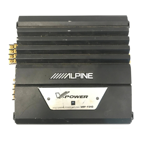
Alpine 3554 User manual

SERVICE
MANUAL
ZILPIN
4/3/2
Channel
Power
Amplifier

3554
Contents
SPECiICALIONS:
sida
5
cue
SR
SPARE
RS
Lea
peter
rae
ete
ice
pate
A
ae
ens
2
FeatureS
0...
cece
ccc
een
eee
eee
eee
e
ener
n
teen
nee
3
Switches
and
Terminals
........
00...
c
eee
eee
enter
tenet
et
een
es
4
Switch
Settings
«00.2.0...
ccc
c
cece
e
eee
teeter
eee
een
e
eee
ene
n
eens
ent
n
enter
eter
nentans
5
Characteristic
CurveS
.......00
0.0
ee
ee
nee
e
nee
e
nee
een
e
eters
6
CORMOOHOIE
-
daeoc
occ
denigh
ised
COR
GRE
ak
EGA
RAO
SR
He
Rae
HE
Madani
OSG GUS
Lote
Eee
s
7
Precautions
...........---+-0--
BPD
og
Me
accent
at
hing
ye
he
deeth
eras
ete
seals
vie
ananc
tits
dete
“g-S
uated
cele
calne
Senne
ae
8
F
Disassembly
Instructions
......
00...
eee
teen
tenet
ee
tenes
9
Block
Diagram
.....2
0.
eee
e
ccc
eect
e
eee
ene
n
ene
n
enn
nese
nen aee
rene
ess
sneenens
10
to
11
Parts
Layout
on
P.C.Boards
and
Wiring
Diagram
......-.
60...
see
eee
eee
eee
tee
e
nes
12
to
14
Schematic
Diagram
.......
2...
center
n
eee
enter
eres
es
15
to
17
iC’s
and
Transistors
Voltage
Values
.......
2.0...
eee
eee
eee
ete
tenet
ees
18
Exploded
View
(Cabinet)
..
0.0.6...
0c
cee
cece
eee
teen
tne
tne
nent
nena
19
to
20
Cabinet
Assembly
Parts
List...
0.0...
cee
et
tenet
nent
t
teens
21
Electrical
Parts
List
2.0.0...
een
eee
nee
eee
net
ent
nna
22
to
25
Packing
Method
View
.........
0.00
c
ccc
e
eee
cette
eee
e
eee
e
teen
ttt
n
eterno
tere
enecnnecnaaes
26
Packing
Assembly
Parts
List
......
2.6.0.
eee
eee
eee
nent
nee
nent
eee
ee
nnn
26
Semi-Conductor
Lead
Identifications
2.0.02...
0.
eet
ete
teens
27
to
29
nn
Specifications
Power
SOUICE
20...
cnn
ee
eee
en
nee
ent
eens
14.4VDC
(11
~
16V)
Current
Drain
(No
Signal)
......
0.0...
e
cece
ene
enter
teen
eee
eet
ee
3.5A
Power
Output
(1
KHz,
0.8%
THD)
....
2.6...
cece
ee
eee
ee
ees
145W/4ch
Input
Sensitivity
0.0...
ete
net
eens
Fixed:
0.5V+
2
dB
Variable:
2V+
2
dB
Frequency
Response
(-10B)
........-.
00.
see
eee
eee
tenet
eee
teens
20
Hz
~
40
kHz
Signal
to
Noise
Ratio..............-.-55--
sgt
BB
eS
ang
a's
cadon
tiie
gia
eager
Th
asatn)
ans
atedncererics
100
dB
Separation
0...
cceee
cutee
ee
a
ee
re
deel
tine
ewe
een
ee
eee
ea
Re
eee
na
de
ede
eens
.
56dB
Input
Impedance
....
1.6.66.
ee
ete
teen
tenes
10
kohm
+
2
kohm
Output
Impedance
..
6.6
ee
ett
eee
eee
n
eee
.
4o0hm
Output
Noise
...
26.0.6...
cece
eee
eee
erent
een
e
tence
reat
ee
ene
e
ena
ene
enee
atin
st
1mvV
Semiconductors
...........
0.00.
eee
eee
eee
13
IC’s,
51
Transistors,
29
Diodes,
6
Zener
Diodes,
2
LED's
Dimensions
......
0.0.00
cc
eee
ete
e
enn
285(W)x
55(H)
x
300(D)
mm
:
WEIGHT
token
piste
Cais
cae
kdod
Sawa
a
SU
Rg
eee
lee
ht
eet
ed
Fee
Veena
eas
4.15
kg
_
NOTE:
Due
to
continuing
product
improvement,
specifications
and
design
are
subject
to
change
without
notice.
e

Features
e
4/3/2-Channel
Operation:
The
3554
can
be
used
in
3
ways
as:
a.
4-channel
full-range
amplifier,
producing
50W
per
channel
into
4
ohms,
or
75W
per
channel
into
2
ohms.
The
amplifier
can
be
used
in
a
4-speaker
full
range
system
or
in
a
bi-amped,
dual
subwoofer
and
dual
satellite
combination.
b,
3-channel
amplifier,
producing
50W
(4
ohms)
or
75W
(2
ohms)
into
channels
1
&
2,
and
150W
(4
ohms)
into
the
third
channel.
This
combination
is
perfect
for
a
single
subwoofer,
dual
satellite
(right
and
left)
system.
c.
2-channel
full-range
amplifier,
producing
150W
per
channel
into
4
ohms.
The
amplifier
can
be
used
as
full
range,
low-pass
(sub-woofer
amp),
or
high-pass
(satellite
amp).
e
Status
Monitor:
This
indicator
illuminates
in
green
when
the
3554
is
on
and
operational.
This
light
will
turn
orange
if
any
protection
circuitry
is
activated.
It
can
be
used
as
a
troubleshooting
aide
should
an
installation
problem
develop.
e
Active
Dividing
Network:
Abuilt-in,
switchable
electronic
crossover
network
at
80
Hz,
18
dB
per
octave
can
be
used
to
set
up
the
amplifier
for
low-pass
(subwoofer)
or
high-pass
(tweeter/midrange
satellite)
applications.
This
network
can
also
be
switched
off
to
allow
full-range
signal
amplification.
e
Duo-B
Feedback
Circuitry:
Duo-Beta
is
a
patented
and
technologically
advanced
form
of
negative
feedback.
Negative
feedback
is
used
to
minimize
distortion
and
stabilize
the
amplifier.
Too
much
feedback,
however,
increases
the
transient
intermodulation
distortion
(T.I.M.),
decreases
the
amplifier
slew
factor,
and
reduces
its
musicality.
The
Duo-Beta
circuitry
supplies
low
negative
feedback
throughout
the
audio
frequency
and
very
high
negative
feed-back
at
DC.
This
stabilizes
the
amplifier,
removes
DC
offset,
and
offers
excellent
total
harmonic
distortion
(T.H.D.)
characteristics.
It
also
provides
low
T.I.M.,
with
excellent
slew
factor,
stability,
and
musicality.
@
No
Current
Limiting:
Current
limiting
circuitries
used
in
conventional
amplifiers
may
cause
premature
clipping
and
inferior
transient
response.
Absence
of
current
limiters
in
the
audio
section
ensures
low
T.I.M.,
excellent
transient
response,
and
superb
sonic
quality.
e
S.T.A.R.
Circuitry:
Alpine
proprietary
Signal
Transit
for
Accurate
Response
circuit
topology
improves
sonic
properties
by
reducing
interaction
between
different
sections
of
the
circuitry.
3554
e
Input
Mode
Selector:
This
switch allows
the
user
to
specify
the
input
signal
entering
the
amplifier:
a.
Stereo
Mode:
Allows
the
right
and
left
channel
signals
to
reach
their
designated
amplifier
channels.
This
mode
provides
a
stereo
output
or
a
center
channel
common
information
output
(when
used
in
the
bridged
configuration).
b.
L
(MONO)
Mode:
Disables
the
right
channel
input
connector
and
routes
the
signal
through
the
left
channel
input
to
all
sections
of
the
amplifier.
This
mode
can
be
used
when
a
single
(mono)
signal
is
amplified
(either
in
stereo
or
bridged
operation).
.
L+R
Mode:
Sums
the
right
and
left
channel
input
signals
and
routes
the
result
to
all
sections
of
the
amplifier.
It
can
be
used
in
stereo
or
bridged
operation
to
provide
a
summed
(mono)
output.
(2)
e@
DC-to-DC
Switching
Mode
Power
Supply:
Provides
excellent
power
output
throughout
the
audio
bandwidth
(20
Hz
to
20
kHz).
Its
soft
clipping
characteristics
ensure
superb
transient
response
and
musicality.
e
Fully
Complementary,
Discrete
Output
Circuitry:
For
excellent
reliability,
superb
sonic
performance
and
high
current
capability
for
accurate
transient
response.
e
Continuously
Adjustable,
Independent
Front
and
Rear
Input
Gain
Controls:
Allow
different
level
settings
for
the
two
different
audio
sections.
e@
Heavy
Duty
Construction:
Glass-epoxy
printed
circuit
boards
for
excellent
thermal
stability
and
long-term
reliability.
e
Gold-Plated
RCA
input
Connectors:
For
most
accurate
signal
transmission
and
lowest
possible
loss.
Gold-plated
terminals
are
immune
to
signal
deterioration
caused
by
corrosion
in
the
connectors
that
can
develop
over
time.
@
Gold-Plated
Speaker
Output
and
Power
Connectors:
For
high
definition,
minimum
loss
power
transfer
and
oxidization
resistance.
@
High
Performance,
Low
Noise,
Audiophile
Quality
Active
and
Passive
Components.
@
Capacitive/inductive
Power
Supply
Input
and
Output
Filtering:
For low
radio
frequency
interference
(RFI)
and
immunity
to
system
noises
(such
as
alternator
whine).
@
Fully
Protected
Against
Wiring
Errors.

3554
Switches
And
Terminals
PDQQOVOOO@
OO
OOOHOO
Input
Mode
Selector
Switch
(Channels
1/2)
Active
Dividing
Network
Mode
Selector
Switch
(Channels
1/2)
Input
Gain
Selector
Switch
(Channels
1/2)
Input
Gain
Adjustment
Control
(Channels
1/2)
Input
Gain
Adjustment
Control
(Channels
3/4)
Input
Gain
Selector
Switch
(Channels
3/4)
Active
Dividing
Network
Mode
Selector
Switch
(Channels
3/4)
Input
Mode
Selector
Switch
(Channels
3/4)
Input
RCA
Jacks
(Channels
1/2)
Speaker
Output
Terminals
(Channels
1/2)
Fuse
Blocks
Power
Terminals
Remote
On
Connector
Speaker
Output
Terminals
(Channels
3/4)
Input
RCA
Jacks
(Channels
3/4)
Status
Monitor

Switch
Settings
Input
Mode
Selector
Switches
@
and
©:
a)
Set
to
the
“ST”
position
(center)
when
the
amplifier
is
used
as
a
4-channel
stereo
system.
ro
L(MONO)
ST
L+R
b)
Set
to
the
"L
(MONO)"
position
when
the
amplifier
is
used
for
one
channel
of
a
stereo
or
bridged
system.
a
L({MONO)
ST
L+R
c)
Set
to
the
"L+R"
position
when
the
amplifier
is
used
for
the
subwoofer
system
which
uses
the
right
channel
and
left
channel
signals
summed.
—
L(MONO)
ST
L+R
Active
Dividing
Network
Selector
Switches
@
and
©
a)
Set
to
the
"LP"
position
when
the
amplifier
is
used
for
the
low-pass
(sub-woofer)
system.
The
frequencies
higher
than
80
Hz
will
be
cut
(at
a
rate
of
18
dB
per
octave).
b)
Set
to
the
"HP"
position
when
the
3554
is
used
for
the
high-pass
(tweeter/midrange
and
subwoofer)
system.
The
frequencies
lower
than
80
Hz
will
be
cut
(at
a
rate
of
18
dB
per
octave).
TS
OFF
HP
LP
3554
c)
Set
to
the
"OFF"
position
when
the
3554
is
used
for
the
regular
stereo
system
with
full-range
speakers.
The
full
bandwidth
will
be
output
without
cutting
the
high
or
low
frequencies.
pe,
OFF
HP
LP
Fixed/Variable
Input
Selector
Switches
@
and
©:
a)
Set
to
the
"FIXED"
position
when
connecting
the
3554
to
other
Alpine
products.
This
position
sets
the
input
sensitivity
to
500
mV
which
corresponds
to
the
pre-amp
output
of
Alpine
products.
r—
L_
VARIABLE
FIXED
b)
Set
to
the
"VARIABLE"
position
when
connecting
the
3554
to
a
non-Alpine
product
with
an
output
voltage
other
than
500
mV.
This
position
should
also
be
used
when
adjustment
of
input
sensitivity
is
required
to
obtain
certain
imaging
requirements
or
to
compensate
for
different
speaker
efficiencies.
ane
|
VARIABLE
FIXED
Input
Gain
Controls
®
and
©:
After
setting
the
Input
Select
Switches
@
and
©
to
the
"VARIABLE"
position,
rotate
the
Input
Gain
Controls
4
and
5
with
a
#0
screwdriver
and
adjust
the
input
gain
to
the
point
where
there
is
maximum
volume
with
no
distortion.
Status
Monitor:
This
indicator
lights
green
when
the
power
is
on.
The
3554
has
built-in
protection
circuitry.
If,
for
some
reason,
this
protection
circuit
is
activated,
the
indicator
turns
orange.
If
this
happens,
turn
the
system
off,
find
the
cause
of
the
problem
and
remedy
the
situation.
This
includes
checking
all
your
connections
and
wiring.
If
the
indicator
remains
orange
when
the
system
is
turned
on,
consult
yourauthor-
ized
Alpine
dealer.
Note:
The
indicator
will
illuminate
in
orange
for
a
iew
seconds
when
the
power
is
turned
on
as
the
protection
circuit
will
be
activated.
This
is
normal.

3554
Characteristic
Curves
POWER
VS.
DISTORTION
CURVE
cA
200
T.H.D.
(%)
“=
HH
0.01
0.01002
0.05
0.1
1
2
5
10
20 50
100
OUTPUT
POWER
(W)
FREQUENCY
RESPONSE
CURVE
a
en
|
OS
|
aE
0
1
eee
a
O01
0
Coon
oo
an
On
Coo
Co
RESPONSE
(dB)
10
«6200
50
100s
«200
500
1K
2
FREQUENCY
(Hz)

Connections
Insulation
Tubes
(INCLUDED)
Before
making
connections,
be
sure
to
turn
the
power
off
to
all
audio
components.
Insulation
tubes
for
the
speaker
leads
and
the
power
supply
leads
are
supplied
with
the
3554,
route
the
speaker
leads
and
the
power
supply
leads
separately
through
these
tubes.
1.
Speaker
Output
Terminal
The
3554
has
two
sets
of
speaker
outputs
for
the
Front
and
Rear
speakers.
Be
sure
to
observe
correct
speaker
output
connections
and
phasing.
In
the
stereo
mode
connect
the
right
speaker
output
to
the
right
speaker,
and
the
left
to
left.
Connect
the
positive
output
to
the
positive
speaker
terminal,and
the
negative
to
negative.
In
the
bridged
mode,
connect
the
left
positive
to
the
positive
terminal
on
the
speaker,
and
the
right
negative
to
the
negative
terminal
of
the
speaker.
Do
not
use
the
speaker
(-)
terminal
commonly
for
the
right
and
left
speakers
or
connect
it
to
the
vehicle’s
chassis
ground.
Note:
Do
not
connect
speaker
leads
together
or
to
chassis
ground.
3554
(INCLUDED)
Remote
On
Lead
(Blue/White)
e{C>
Ground
Lead
(Black)
Pas
Battery
Lead
(Yellow)
2.
Ground
Lead
(Black)
Connect
this
lead
securely
to
a
clean,
bare
metal
spot
on
the
vehicle’s
chassis.
Verify
this
point
to
be
atrue
ground
by
checking
for
continuity
between
that
point
and
the
negative
(-)
terminal
of
the
vehicle’s
batiery.
3.
Battery
Lead
(Yellow)
Connect
this
lead
directly
to
the
positive
(+)
terminal
of
the
vehicle's
battery.
Do
not
connect
this
lead
to
the
vehicle’s
electrical
system.
4.
Remote
Turn-On
Lead
(Blue/White)
Connect
this
lead
to
the
remote
turn
on
lead
of
your
head
unit.
;
5.
Input
RCA
Jacks
Connect
these
jacks
to
the
line
out
leads
on
your
head
unit
using
optional
RCA
extension
patch
cords.
Be
sure
to
observe
correct
channel
connections;
Left
to
Left,
Right
to
Right,
Front
to
Front,
and
Rear
to
Rear.
Three
simple
and
typical
system
combinations
are
illustrated.
For
wiring
connections,
carefully
follow
the
instructions
provided
with
each
component.

3554
Precautions
_
iw)
wo
.
Improper
wiring
connections
could
cause
damage
to
your
vehicle’s
electrical
system
and/or
the
3554
amplifier.
Carefully
follow
the
wiring
instructions
in
this
manual.
.
Attaching
the
battery
lead
to
the
positive
(+)
terminal
of
the
battery
should
be
the
last
connection
after
all
other
connections
are
made.
.
Due
to
the
high
power
output
of
the
3554,
it
is
important
that
all
connections
are
clean
and
well
secured,
or
damage
could
result.
.
Be
sure
that
the
3554
is
mounted
in
a
way
that
will
allow
for
free
air
circulation
and
heat
dissipation.
.
When
changing
fuses,
be
sure
to
replace
the
old
fuse
with
one
of
the
same
amperage.
Use
of
improper
fuses
can
lead
to
serious
damage
to
components.

Disassembly
Instructions
1.
Removal
of
Bottom
Cover.
(1)
Remove
four
screws
marked
"O
"as
shown
in
Figure
1.
(2)
The
Bottom
Cover
will
be
removed
by
pulling
out
in
the
arrow
direction
as
shown
in
Figure
1.
2.
Removal
of
Amp
P.C.Board.
(1)
After
removal
of
the
Bottom
Cover,
remove
31
screws
marked
"
@".
Then,
the
Amp
P.C.Board
will
be
removed
from
heat tank
together
with
Rear
Chassis
and
RCA,
Output
Connector
and
Power
P.C.Board
as
shown
in
Figure
2.
(2)
Remove
two
screws
marked
"MM
_"
and
the
solders
located
two
placed
as
shown
in
Figure
3.
(3)
After
removal
of
two
pieces
of
fuse,
remove
seven
screws
marked"
&
"
and
the
hooks
located
at
six
places
as
shown
in
Figure
4.
(4)
After
the
above
procedures
are
completed,
RCA,
Output
Connector
and
Power
P.C.Board
is
ready
to
be
removed
from
Rear
Chassis
together
with
the
Main
P.C.Board.
Figure
3
BOTTOM
COVER
REMOTE
P.C.Board
RCA
P.C.Board
OUTPUT
CONNECTOR
P.C.Board
Figure
2
FUSE
HOOK
Figure
4
Block
Diagram
FILTER
$102-|
eH)
Icio
1/2)
Ae
ret
1e2021I/2)
ql
LOW
PASS
FILTER
AMP
Ic2ol(1/2)
pyr
siol-t
vRIOI~|
ay
GAIN
CONTROL
VARIABLE
ETIO2-1
CHI
@—-
R-CH
(R-CH)
exigass
HIGH
PASS
aa
BUFFER
FILTER
AMP
iceoi
2)
(L-CH)
1€302
(1/2)
OFF
INPUT
MODE
{
$301-|
LOW
PASS
L
MONO
$20!-|
FILTER
AMP
'
VR301-1
FIXED
\C401(1/2)
GAIN
LP
ST
CONTROL
VARIABLE
R-CH
{
L+R
ETIO2-3
CH3
~©@+-—>
R-CH
(R=CH)
DRIVER,
POWER
Amp,
Te
—
STAGE
—
0503,504
Dc—pCc
REGULATOR
BUFFER
1.
V-
STABILIZER
CONVERTER
SWITCHING
—STAGE-
Q530
CONTROL
Q501—
514
Ic501
BUFFER
—
STAGE—
~
V-STABILIZER
Q53)
DRIVER,
POWER
AMP.
—
STAGE-
-B
SWITCHIN:
Q5I6

roa
re
2
re
4
Block
Diagram
rCHe
©
BUFFER
G
aon
iclo1
(172)
‘ll
yD
siol-I
VRIOI~|
one
GAIN
CONTROL
VARIABLE
ET1I02-|
cH|
@—»
R-cH
(R-CH)
ETIO2-4
BUFFER
CH4
(L-cH)
1€301
(1/2)
S20I-1
VR30I-1
FIXED
GAIN
CONTROL
—
VARIABLE
ETI02-3
CH3
~©@+—>
R-CH
(R-CH)
DRIVER,
BUFFER
~stace-
78
BUFFER
—
STAGE-
~
DRIVER,
POWER
AMP.
—
STAGE-
V-
STABILIZER
0531
HIGH
PASS
FILTER
AMP
1c102
(1/2)
LOW
PASS
FILTER
AMP
Ic201(1/2)
HIGH
PASS
FILTER
AMP
1€302
(1/2)
LOW
PASS
FILTER
AMP
IC401(1/2)
+8
503,504
—10—
FILTER
$l02-|
c
BUFFER
:
|
1c202(1/2)
OFF
INPUT
MODE
t
$103-I
I
L
—
LP
ST
Race
t
R
0C—DC
CONVERTER
Q501—
514
SWITCHING
Q516
Q517
MUTE
SWITCH
cI
+B
OVER
LOAD
QO
®
PROTECTOR
103
DRIVER
(2)
ETIO!
IClo3
LEFT
OVER
LOAD
rite
pa
106
MUTING
Qiol
MUTING
as
9301
RIGHT
OVER
LOAD
PROTECTOR
0303
&)
3}
LEFT
OVER
LOAD
@
[es
POWER
PROTECTOR
(9X0)
AMP
9304
Ss
=
0306
R-CH
&)
RIGHT
THERMAL
&
OVER
LDS5I9-!
CURRENT
LED
SWITCH
@
(GRN)
REGULATOR
0524
LD520-1
SWITCHING
(GRN)
CONTROL
LED
SWITCH
p)
L0519-2
IC501
Q525
(ORG
)
LD520-2
(ORG
}
Dc-pCc
CONVERTER
+B
Bt
Tee!
FIOI
ET5OI
Ic50l
SWITCH
7
oN
©
1BATT
515
T502
Fl02
GND
Bt
SWITCH
ET502
Q521
4
MUTE
SWITCH
Rew
9518,
0523
—-11—-
fo
Jremote
3554

3554
Parts
Layout
on
P.C.Boards
and
Wiring
Diagram
LD5I9
-1,
LDSI9-2,
LO520-1,
LD520-2
{(GRN)
(ORG)
RED
[ern
_|
lory
BLU
LED
PC.
Board
Amp
PC.Board
$103
INPUT
MODE
RCA
P.C.Board
L(MONO)
<
7
t
ST
f
L+R
sio2
FILTER
OFF
{
HP
'
LP
SI0l
GAIN
CONTROL
FIXED
{
VARIABLE
=
x
=
VRIOI,
301
GAIN
CONTROL
$201
GAIN
CONTROL
VARIABLE
FIXED
$202
FILTER
yr3y
OFF
|
4;
4
1
HP
1
<I
"
|
es
uP
24}
Of
Pate
ie
iL!
!
i)
~
wa
BLU
2.
eens
Blue
GRN..........
Green
$301
BLK.
cise
Sere
Black
(NPUT
MODE
GRY..........
Gray
L
(MONO)
WHT..
..
White
{
RED..
..
Red
ST
BRN
..
..
Brown
ORG..
.
Orange
t
YEL
Yellow
L+R
VIO...
Violet
PNK...
Pink
—-12—

Remote
P.C.Board
Output
Connector
P.C.
Board
LEFT
BLK(L)
|
BLKIZ)
Jo
os
BRIDGE
BLKI4)
|
RIGHT
—~14—

Schematic
Diag
ramM
(Refer
to
reverse
side
for
IC’s
and
Transistors
voltage
values.)
[
71
Tamp
PC.
Board
T
|
RIZ5
12K
‘
Q105_28c4387
+¢——
Q103
;
oll
Ios
eae
eerie
Secale
OE
|
pPCI270H
Q
OF
-
_
|
|
ROL
EIOL
[Power
AMP]
AMP
wo)
BIAS
‘OAD
a
ETIO2-2
x
1K
1O6
Ri
E104
a
=
j
CH2
(QoS
=
a:
Fah
1K
10/16
Ri22
DRIVER
(24
LION
it
i
Sh
STK
STAGE
3
OT:
agz
38
$102-1
Cy
Loy
bbe
_2
|
on
FILTER
ai
RI4I
(vs
|
ont
ofr
on
i
HP
E
|
|
t
$103
-I
RISC
|
up
INPUT
MODE
10K
(p>
(ve
Q104
a
AT
:
Pan
CO)
x
i
Qf0l~
514
|]
re:
3
e
|
|
Wl
viol
:
CONVERTER
|
|
s
;
2
oa
aad
:
x
MUTING
|
&
=s
D103,104
|
|
|
1$S133
|
+
| |
Ic102
1C201
Ic202
—
228
(C101
0205_25¢4387
aS
|
l
|
wPC457OHA
|
C457OHA
PCASTOHA
wPcaszOun
DRIVER
is
5
1
LOW
PA
[BUFFER
|
4
|
l
|
AN
ae
FILTER
AMP
rere
R237
Q
D205
|
85
|
jouer
a
PeizTOH
zs
ISSI76
[ce
l
|
(PoweR_
ane]
=
|
e201
£201
'
{se
ad
eTIOg-1
3
IK
love
|
fone.
|
8°
ano
:
=m
Sxe
35
ESS
|
|
|
=e]
Sa
R241
10
|
Om)
(Iw)
CURRENT
MIRROR
|
R230
LOAD
9204
+
sioz
$103
ek
A733,
|
|
#9
ue
ate
ie
‘
een
connector
|
°
{
£201
8
PC.Board
(1/2)
|
2SC3327
2
DC.
||
e205
[wots]
g
|
$9
vRlol-
2
FIxeD
0206
2541672
34
|
0203,204
|
|
GAIN
'
8
1$S133
|
CONTROL
VARIABLE
|
|
R325
2K
030:
4387
I
Lg
ifs
aa
R337
0305
|
|
pitas,
i
=
ac
ving
Bee’
abla
=
aa
ISSI76
REFERENCE
|
|
8
arm
[eres
[|
ap
ae
CHa
Qh
ie
ice
DIFFERENTIAL
|
eed
5S
S|
AMPLIFIER
||
By
|
,
ae
se
aoe
8
2
|
L_
MONO
onal
Ke)
OVERLOAD
fon
|
||
:
930
5
ee
|
SF
ss
||
2
as
oo
||
fi
:
tit}
lige
T°?
fy
|
Gal
:
303,304
Sf
be
|
|
CONTROL
VARIABLE,
1SS133
eee
ae
ene
|
;
:
Q519
0520
|
|
|
R425
12K
254733
2SC945
1
——
{SWITCHING
|
——
(C301
!
1¢302
Ic401
Ico!
|
|
|
ppcas7oHa
i!
yPC4570HA
PC4570HA
»PC4570HA
Oe
mel
T
Gees
\
HIGH
PASS
LOW
PASS
BUFFER
|
|
i
FILTER
AMP
FILTER
AMP
Agr
D405
|
!
oo
vcicoueaieside
1C403
1SS176
|
|
4
R444
|
R4oi
E401
'
~
Q516
52!
er192=3
Jf
IK
OG
!
Re
@SBIO76M
—2SAIIIS
|
cCH3
GRY
arm
ee
2h)
4K
“SWITCHING
MUTE
|
|
av
l
33
®
i
O—
7
SWITCH
|
54
28
ee
©
0518
|
oP
25945
Q523
R536
R43)
|
|
|
¥
$202.
$301
33k
TooK
0K
7
se
2SC3615
|
|
|
FILTER
INPUT
MODE
1)
et
Bok
‘
cede
tile
pee
2750
|
fs
ae
0401
Fd
‘
—
9x
283327
:
_
er
:
‘
Bp
|
|
fiting
:
Fe)
I
Won
FED
0404
2sal67e
Sf
|
0403,404
Fest
~
| |
Gain
3
1SS133
r
oe
CONTROL
VARIABLE
hee
ite

3554
NOTE:
Ita
lues
1.
All
resistance
values
are
in
ohms.
K=
1,000
M=
1,000,000
roltage
values.)
2.
All
capacitance
values
are
in
microfarads.
P=
1/1,000,000
joe
ye
Eh
ee
a
ee
a
ee
SS
ee
ae]
San
per
5
eran
ge
ie
ey
20505,506
|
Roe
SBI
101
ea
|
i
Qi05
387
o—+¢-
|
9103
D105
|
]
530
BS
Sly
9g
+
2
+
se
+
1L8o
4
|
z
DIOS
ne
bt
ad
oa
Soa
Soa
Ssu
=85
NS
:
1C103
oe
VERLOAD
PROTECTOR:
1SSI76
V.
STABILIZER
ase
eS]
wR
we
cs
as
yPCI270H
REFERENCE
CONSTANT
wn
“
|
POWER
AMP
BIAS
ORD
|
|
|
RIVER
ag:
Le
Te
ce
2sai3s8
|
AMPLIFIER
veti/2)
hou
RI4I
V_
STABILIZER
}_}
oO
:
a
|
CURRENT
MIRROR!
|
LOAD
COMPENATION
104}
gio
if
OK
BSATSS
Qf0l
~
514
o501
|
dC
-0C
2SA
28
a
|
‘vine|
g
|
MUTING
=
is
o10¢_2gale72
Sf
|
103,104
E
1S$133
at
|
pen
ee
ee
ey
R225.
12K
8
|
Q
Ii
|
202
b
Q205_2SC4387
-—1¢—4
|
=°S7
Ls
I
erone
O-®
(1)
ORIVER
9203
3
0205
|
38
|
l
i
|
1c208
_
Po
ean
eres
ere)
Sar
4
|
gue
|
|
|
244
PCl270H
REFERENCE.
CONSTANT
aaa
} :
:
ps
(Power
ane]
8
pin
aes
.
|
ef
|
cf
a7
SII
w2t2/2)
R222
£205
PROTECTO
;
S
201
|
1
:
fae}
48
sald
fl
&-
AMPLIFIER
;
st
ai
: |
avs
|
é
oe
5
|
;
|
at]
|
o
LOAD
|
|
506
280
4024
.e
o—¢
|
Connector
|
|
osteo
|
PC.Board
(1/2)
|
sali
MUTING
|
Q502
=
!
0206
2sal672
ee
| |
a
0507~
510
OSli~
514
|
1SS133
|
|
2SD1065
2SDI065
|
R325.
12K
|
|
|
030
4387
l
paes
|
1c50l
0305
|
PC494C
|
{C303
ISSI76
|
REFERENCE
pPCI270H
|
|
REGULATOR
|
POWER
AMP.
|
D518~
523
_l
R322
L301
|
|
ISSI76
[=
4.7K
i)
DIFFERENTIAL
Ee
pees
ee
ee
. : :
0524
0525
|
LED
P.C.Board
|
atecerce
|
PRE
DRIVE
=e
|
Test
ert
|
2SC536__RTINI4IS
1
Saar
402
(172)
oF
10
men
——
[LED
DRIVE]
——
|
ro
i
aw)
\"
=
sf
|
=
=
|
|
LO519
,520
CURRENT
MIRROR
TEMPERATURE
;
e|
{°e
RGHy
a
8
AABG4307K
R330
9304
J
9304
Bor
SSRs
es
| |
10K
ae
aes
Foes
é
A733,
I
|
265
3
|
an
OVERLOAD
mm
LD5I9-1
es
ot
(GRN)
Q50!
nal
[eo
[pn
°
‘4
ore
|
S°T
lag
| |
eee
|
7
SS
ax
oe
S$
TSE
(GRN)
ny
on
&
fn
|go8
°
murs
@
303,304
zs
|
|
Eg)
2
20/16
T
ts.
RSTS
LDSi9~2
0306_2SAI672
5
bees
:
+4
ee
10k
(ORG)
DRIVER
3
1SSI33
|
PE
eens
aoe
ae
gs
2
5190520
Joris
20508
8
“ORS
|
25a733_
256945
oy
2
el,
RD22ESB3
Seni
Ras,
1k
—fswitinc]—
B57
g
1
ask
EQ)
28a
l
7
=
Sxz
BSF
zai
Ss
i
erat
o-@
a
ae
ore
if
:
ae:
Pp
ae
wUFFER]
os
om
a5
ous
|
Oe
i;
2K
dee
a
5.6
iP
3S
7
ae
1¢403
om
sg
()
1ssi76
Pp
J|
788
as
|
[7
Te
Remote
Raga
PCI270H
A
CONSTANT
‘
0515
Py
arr
e
an
BS
D516
PC.
Board
10K
fpoweR
ANP]
wo)
BIAS
TOAD
sie
ae
ISSI76
0520
22K
£
BO
ae
1502
ie
REMOTE
.
28
—
at
SBIO76M
—2SAIIIS
wal
402
(2/2)
DRIVER
(2)
L401
atcned
Q5i5
ARH
|
Lu
ES2
ET502
STAGE
.
MUTE
coe.
OENPLIBIER
PRE:
DRIVE
(Dee
SwiTcH
heel
Z0511
Oe
eer
be
ag
Cy
2%
Ts0l]
p5i7
518
|
-—
em
3004
E7501
a
|
0518
e,
3
Tost0
9522
7
7
28¢945
RY)
Sx
BES
|
asge
|
ZO5'
512
60
<x
$4
0515
BATT
0523
3 o
22K
RD3.9ESBI
oy
S8
=-7
2SA1358
wall!
LOAD
2$C3615
35
S54
720507
SoT
ze
oT
RDG6.2ESBI
er
wires]
|
BF
500,516
B=4
SF
k
ee
Z
3
@ ©
°
osu
|
'SsI76
,
es
oN
O87
BRAKE
F101,
102
ey.
:
_
:
at)
RTINIGIS
|
[ccs
g
10k
<7
CH
ox
LoS
emt
kes
Joutput
0403
,404
UN
ry
ex
an
Boay
Teck
|
|
Connector
1SS133
3
3
Bs
a
P.C.Board
~
JL
_jitavai

3554
IC’S
And
Transistors
Voltage
Values
[Pin
No.
|
IC101
|
IC102
|
IC201
|
IC202
15.3V
12mV
}smV_
ov
{ov
|
10mv
7
0
-15.1V
|smV__
[ov
ov
|
tomv
7
|smv_fov_
[ov
|
tomv
a
2
Pe
ov
}
4
[smv_
tov
jov_
|
tomv
|
5
|
-
|
6
OV
eae
ov
TamV
IC
Ic103_
|
1C203
1C403
35.6V
35.6V
[Pin
No.
|
=
ay
be
|
2
«|
38.6V
5.6V
:
|
3
(|
34v
sav
gay
|
4
ieee)
aa
aa
0.1
:
lo.1v.
[0.1
.
|
-34v_
|
-34v__
|
-34v_
|
7
-35.6V
-35.6V
08v
Ic301_|
IC302_
|
IC402
[Pin
No.
|
Pt
[15.av_
|
15.3v_|
15.3v_|
P|
2
|
4omv
|
7mv__
|
tamv
|
P
4
[smv_fov_[
tomv
|
Ps
|
-15.1v
|
-15.1v
|
-15.1V
Eee
V
i
Ail
V
s
O/O};o
2
£}2/2/=
2
<|<|/<
ako)
0
|
aioa
[ov
|
-2iv
[ov
|
aios
|
2.5mv
|
35.6v
|
05v
|
|
Q106__|
-3mv_|
-35.6v
[-0.7V_|
|
a201_
joy
tov
[ov
|
|
a2o2_
|
-1.2v
[oav_
[-osv
|
|
a205__
|
25mv
|
35.6v
|osv
|
|
Q206
|
-3mv_|
-35.6v
|
-0.7V_|
|
asoa_
[ov
[-2iv
[ov
|
|
a305__|
25mv
|
35.6V
[o.sv
|
|
a306__|
-3amv_|
-35.6v
[-0.7V_|
|
a501_[i4av
[75v
|
isv
|
|
aso
tov
[atv
[osv
|
|
50s
[o7v
[i44v
[tiv
|
|
aso6
fo7v
[144v
[tiv
|
|
asio
[ov
[144v
[osv
|
|
asig
[ov
[sv
[ov
|
|
asig9_
[sv
[ov
[sv
|
|
as2i_
|
iov
[ov
|
t0.6v_|
|
ase5
[osv
[ov [av
|
@
Measuring
Condition
1.
Power
Supply
Voltage
:DC14.4V.
2.
Measuring
Meter
:
Digital
Multi
Voltmeter.
3.
Measuring
Point
Reference
:
Between
Ground.
4.
Measuring
Conditions
:
No
Signal
Input.
—~18—
Exploded
View
(Cabinet)
(C103,203
(C303,
403

3
203
40
’
?
1C103
1C303
S65
—
®
&
ie
ow
o
=
@
S
o
o
xe.
io)
roy
x
it

Cabinet
Assembly
Parts
List
15E06494S01
|
Name
Plate
15E06495S01
|
Holder,
LED
03E06479S01
|
Screw,
Countersink
(M3
x
6)
03E06480S01
|
Screw,
Pan
(M3
x
6)
36E06376S01
|
Lens,
LED
36£06482S01
|
Base,
Lens
15E06483S01
|
Guide,
Lens
75E06484S01
|}
Spacer,
LED
43E£06498S01
|
Spacer,
Switch
75E06485S01
|
Cushion,
Switch
43E06486S01
|
Cover,
Switch
43E06718S01
|
Cover,
Switch
A
04E06487S01
|
Washer,
Flat
(M3)
01E06717S01
|
Terminal;
Lug
GND
03E06488S01
|
Screw,
Pan
(M3
x
11.5)
With
Washer
03E06489S01
|
Screw,
Pan
(M3
x
9.5)
With
Washer
03E06490S01
|}
Screw,
Pan
(M3
x
6)
03E06491S01
|
Screw,
Pan
(M2
x
6)
03E06492S01
|
Screw,
Bind
(M3
x
5)
15A81675F01
|
Insulator,
Power
Transformer
03E06493S01
|
Screw,
Countersink
(M3
x
6)
26A81610F02
|
Shield,
CU
15E06453S01
|
Holder,
Auto
Fuse
NOTE:
The
parts
without
part
numbers
are
not
supplied.
~o4=
|
3554

3554
Electrical
Parts
List
Oo.
Abbreviations
CAP.
=
Capacitor
ELY.
=
Electrolytic
RES.
=
Resistor
C.F.
=
Carbon
Film
M.F.
=
Metal
Film
CER.
=
Ceramic
M.O.
=
Metal
Oxide
Film
MYL.
=
Mylar
N.P.
=
Metal
Pilate
TAN.
=
Tantalum
POLY.
=
Polystyrol
PP.
=
Polypropylene
PLT.
=
Polyethylene
TR.
=
Transistor
TRANS.
=
Transformer
CP.
=
Chip
Amp
P.C.Board
51T83403F03
|
uPC4570HA
51T83403F03
{|
uPC4570HA
51£03492S01
|
wPC1270H
51T83403F03
|
uPC4570HA
51T83403F03
|
uPC4570HA
51E03492S01
51T83403F03
51T83403F03
51E03492S01
51T83403F03
uPC1270H
uPC4570HA
wPC4570HA
wPC1270H
uPC4570HA
51E03492S01
51T70759F01
51T83403F03
uPC1270H
uPC494C
uPC4570HA
Transistors
48E06355S01
48T64376F01
48E06455S01
48E06356S01
48E06363S01
2SC3327
2803423
280945
2SA733
2804387
48E06364S01
48E06355S01
48T64376F01
48E06455S01
48E06356S01
2SA1672
2SC3327
2303423
2SC945
2SA733
48E06363S01
48E06364S01
48E06355S01
481T64376F01
48E06455S01
2504387
2SA1672
2503327
2803423
280945
48E06356S01
48E06363S01
48E06364S01
48E06355S01
48T64376F01
2S8A733
2SC4387
2SA1672
2SC3327
2803423
48E06455S01
48E06356S01
48E06363S01
48E06364S01
48E06356S01
280945
2SA733
2804387
2SA1672
2SA733
Resistors:
Carbon
resistors
under
1/4
watts
are
not
mentioned
in
the
parts
list,
please
confirm
them
by
schematic
diagram.
uF
=
microfarads,
pF
=
picofarads.
ye
Part
No.
Description
|
||
0.
48E06356S01
2SA733
48E06455S01
280945
48E06455S01
280945
48T16440W01
|
2804024
48T16440W01
|
2804024
48T47613F01
28D1065
48747613F01
2SD1065
48T47613F01
2SD1065
48T47613F01
2SD1065
48T47613F01
2SD1065
48T47613F01
2SD1065
48T47613F01
2SD1065
48T47613F01
2SD1065
48T70761F01
2SA1358
48T81069F01
2SB1076M
48E06350S01
RT1N141S
48E06455S01
280945
48E06356S01
2SA733
48E06455S01
280945
48E06348S01
2SA1115
48£06347S01
2802603
48E06358S01
2803615
48E06454S01
280536
48E06350S01
RTIN141S
48T69176F02
|
2SC3421
48T70761F01
2SA1358
Diodes
48T68829F01
18S133
48T68829F01
18S133
48T58583F01
1SS176TA
48T68829F01
18S133
48T68829F01
1$S133
48T58583F01
1SS176TA
48T68829F01
188133
48T68829F01
18$133
48T58583F01
1SS176TA
48T68829F01
1$$133
48T68829F01
1SS133
48T58583F01
1SS176TA
48T58583F01
1SS176TA
48758583F01
1SS176TA
48E04804S01
F10P20F
48E04803S01
F10P20FR
48T58583F01
1SS176TA
48T58583F01
1SS176TA
48T58583F01
18S176TA
48T58583F01
1SS176TA
48T58583F01
48E06456S01
48E06456S01
1SS176TA
30D4
30D4
_22—

|
3554
Oo.
48T58583F01
1SS176TA
48T58583F01
1SS176TA
48T58583F01
1SS176TA
48T58583F01
1SS176TA
48T58583F01
1SS176TA
Symbol
Part
No.
Description
No.
23E04816S01_
|
ELY,,
10uF/16V
21£06322801
|
CER,
47pF
O8E06460S01_
|
MMT.,
0.15yF
23E04816S01
|
ELY.,
10pF/16V
08E06463S01
|
MMT.,
0.068yF
23604816801
|
ELY.,
1OpF/16V
08E06459S01
|
MMT,
0.1pF
23E04816S01
|
ELY.,
10yF/16V
08E06459S01
|
MMT.,
O.1pF
23E06330S01
|
ELY,,
(B.P.)
100uF/10V
21£06324S01
|
CER,
220pF
23E04826S01
|
ELY.,
0.47pF/50V
21E06321S01
|
CER.,
33pF
23E04826S01
|
ELY.,
0.47pF/50V
08E06462S01_
|
MMT,
0.047pF
23E06329S801
|
ELY,,
1.5uF/50V
23E06327S01
|
ELY.,
0.22uF/50V
21£06324801
|
CER,
220pF
23E04816S01
|
ELY.,
10uF/16V
21E06322S01
|
CER.,
47pF
08E06460S01_
|
MMT.,
0.15pF
23E04816S01
|
ELY.,
10WF/16V
08E06463S01
|
MMT.,
0.068
uF
23E04816S01
|
ELY.,
10pF/16V
08E06459S01
|
MMT,
0.1yF
23E04816S01
|
ELY.,
10yF/16V
08E06459S01
|
MMT.
0.1pF
23E06330S01
|
ELY.,(B.P.)
100uF/10V
21E06324S01
|
CER.,
220pF
23E04826S01
|
ELY.,
0.47pF/50V
21£06321S01
|
CER.,
33pF
23£04826S01
|
ELY.,
0.47pF/SOV
08E06462801
|
MMT.,
0.047pF
23E04816S01_
|
ELY,,
10uF/16V
23E06329S01
|
ELY.,
1.5uF/50V
23E06327S01
|
ELY.,
0.22uF/SOV
21£06323S01
|
CER.,
100pF
23E06331S01
|
ELY.,
3300yF/16V
21E06323S01
|
CER.,
100pF
23E06331S01
|
ELY.
3300uF/16V
21£06325S01
|
CER.,
560pF
23E06335S01
|
ELY,
2200uF/40V
21E06325S01
|
CER.,
560pF
23E06335S01
|
ELY,
2200nF/40V
21£06323S01
|
CER.,
100pF
23E06335S01
|
ELY,
2200uF/40V
21E06323S01
|
CER.,
100pF
23E06335S01
|
ELY.,
2200uF/40V
08E06458S01
|
TF,
0.12uF
23E06335S01
|
ELY,
—
2200uF/40V
08E06318S01
|
MTL.,
0.47
pF
23£06335S01
|ELY,
2200uF/40V
08E06458S01_
|
TF,
0.12yF
23E04821S01
|
ELY,
100,F/25V
48T58583F01
48E06353S01
48E06353S01
48E06352S01
48E06354S01
1SS176TA
Zener,
RDi6ESB1
Zener,
RD16ESB1
Zener,
RD6.2ESB1
Zener,
RD22ESB3
48E06351S01
48E06351S01
Zener,
RD3.9ESB1
Zener,
RD3.9ESB1
Capacitors
21E06324S01
23E04816S01
21E06322S01
08E06460S01
23E04816S01
CER.,
ELY.,
10pF/16V
CER.,
47pF
MMT.,
0.15pF
ELY,,
10pF/16V
08E06463S01
23E04816S01
08E06459S01
23E04816S01
08E06459S01
MMT.,
;
ELY.,
10mF/16V
MMT.,
0.1pF
ELY,,
10nF/16V
MMT.,
0.1
pF
23E06330S01
21E06324S01
23E04826S01
21E06321S01
23E04826S01
ELY.,
(B.P.)
100uF/10V
CER.,
220pF
ELY.,
0.47pF/50V
CER,
33pF
ELY,,
0.47uF/50V
08E06462S01
23E06329S01
23E06327S01
21E06324S01
23E04816S01
MMT.,
0.047nF
ELY.,
1.5pF/50V
ELY,,
0.22uF/50V
CER.,
220pF
ELY,,
10,F/16V
21E06322S01
08E06460S01
23E04816S01
08E06463S01
23E04816S01
CER.,
47pF
MMT.,
0.15pF
ELY,,
10nF/16V
MMT,,
0.068yF
ELY,,
10pF/16V
08E06459S01
23E£04816S01
08E06459S01
23E06330S01
21E06324S01
MMT.,
0.1pF
ELY,,
10pF/16V
MMT.,
0.1pF
ELY.,
(B.P)
100yF/10V
CER,
220pF
23E04826S01
21E06321S01
23E04826S01
08E06462S01
23E04816S01
ELY.,
0.47.F/50V
CER.,
33pF
ELY,,
0.47pF/50V
MMT.,
0.047pF
ELY,,
10pF/16V
23E06329S01
23E06327S01
21E06324S01
ELY,,
1.5F/50V
ELY,
0.22uF/S0V
CER.,
220pF
99
—

3554
0.
08E06458S01
|
TF.,
23E04821S01
ELY.,
08E06457S01
08E06317S01
08E06458S01
23E06326S01
23E06326S01
23E04833S01
23E06326S01
23E04833S01
23E06326S01
23E06328S01
23E06332S01
23E04866S01
23E06336S01
23E06336S01
ELY,,
470nF/40V
23E06335S01
ELY.,
2200pF/40V
23E06335S01
ELY.,
2200nF/40V
06E06385S01
|
Cement,
0.1
ohm
5Wx2
06E06383S01
06E06385S01
SPR,
10
ohm
1W
Cement,
0.1
ohm
5Wx2
ohm
1W
ohm
5Wx2
06E06383S01
06E06385S01
SPR,
10
Cement,
0.1
06E06383S01
06E06385S01
SPR,
10
Cement,
0.1
ohm
1W
ohm
5Wx2
06E06383S01
SPR,
10
ohm
1W
06E06382S01
SPR,
1
ohm
1W
06E06382S01
SPR,
1
ohm
1W
06E06382S01
SPR,
1
ohm
1W
06E06382S01
SPR,
1
ohm
1W
06E06382S01
SPR,
1
ohm
1W
06E06382S01
SPR,
1
ohm
1W
06E06382S01
SPR,
1
ohm
1W
06E06382S01
SPR,
1
ohm
1W
06E06383S01
SPR,
10
ohm
1W
06E06383S01
SPR,
10
ohm
1W
06E06383S01
SPR,
10
ohm
1W
06E06383S01
SPR,
10
ohm
1W
06E06383S01
SPR,
10
ohm
iW
06E06383S01
SPR,
10
ohm
1W
06E£06383S01
SPR,
10
ohm
1W
06E06383S01
SPR,
10
ohm
1W
06E06384S01
SPR,
100
ohm
1W
06£06384S01
SPR,
100
ohm
1W
06E06387S01
|
Cement,
0.1
ohm
5W
0Q6E06387S01
|
Cement,
0.1
ohm
5W
06E06381S01
SPR,
680
ohm
1/2W
No.
R579
|
06E06381S01
SPR,
680
ohm
1/2W
we
R580
|
06E06380S01
SPR,
560
ohm
1/2W
R581
|
06E06380S01
SPR,
560
ohm
1/2W
Volumes
/
Switches
40E06346S01
Slide,
SSSJ12
(FIXVARIABLE)
Slide,
SSSJ14
(FILTER)
Slide,
SSSJ12
(INPUT
MODE)
40E06344S01
40E06345S01
40E06346S01
‘|
Slide,
SSSJ12
(FIX/VARIABLE)
Slide,
SSSJ14
(FILTER)
40E06344S01
40E06345S01
Slide,
SSSJ12
(INPUT
MODE)
Volume,
50K
ohm
x
2
Volume,
50K
ohm
x
2
18E06386S01
18E06386S01
TD5-C320DA2
20K
ohm
TH501
|
48E06365S01
Coils
/
Transformers
24E06338S01
24E06338S01
24E06338S01
24E06338S01
24E06339S01
Coil,
1.1H
Coil,
1.1pH
Coil,
1.1p1H
Coil,
1.14H
Choke
24E06339S01
25E06343S01
25E06343S01
25E06341S01
Choke
Choke
Choke
Power,
TRANS.
Output
Connector
P.C.Board
08E06459S01
08E06461S01
08E06459S01
08E06461S01
O08E06459S01
08E06461S01
08E06459S01
08E06461S01
Resistors
06E06379S01
SPR,
10
ohm
1/2W
06E06379S01
SPR,
10
ohm
1/2W
06E06379S01
SPR,
10
ohm
1/2W
06E06379S01
SPR,
10
ohm
1/2W
24
—
Table of contents
Other Alpine Amplifier manuals

Alpine
Alpine MRV-100M User manual

Alpine
Alpine PMX-T320 User manual

Alpine
Alpine MRX-M240 User manual

Alpine
Alpine 3522S User manual

Alpine
Alpine MRP-F600 User manual

Alpine
Alpine MRX-F65 User manual

Alpine
Alpine PXE-M60-4 User manual

Alpine
Alpine R2-A150M User manual

Alpine
Alpine MRV-1507 User manual

Alpine
Alpine KTP-445U User manual
Alpine
Alpine MRV-F340 User manual

Alpine
Alpine PDX-V9GC User manual

Alpine
Alpine MRV-F401 User manual

Alpine
Alpine PMX-F640 User manual

Alpine
Alpine S-A60M User manual

Alpine
Alpine 3519 User manual

Alpine
Alpine MRP-F240 User manual

Alpine
Alpine MRV-M1200 Operating manual

Alpine
Alpine PDX-1.600M - Amplifier User manual

Alpine
Alpine MRV-M500 User manual