manuals.online logo
Brands
  1. Home
  2. •
  3. Brands
  4. •
  5. Alpine
  6. •
  7. Cassette Player
  8. •
  9. Alpine 7279M User manual

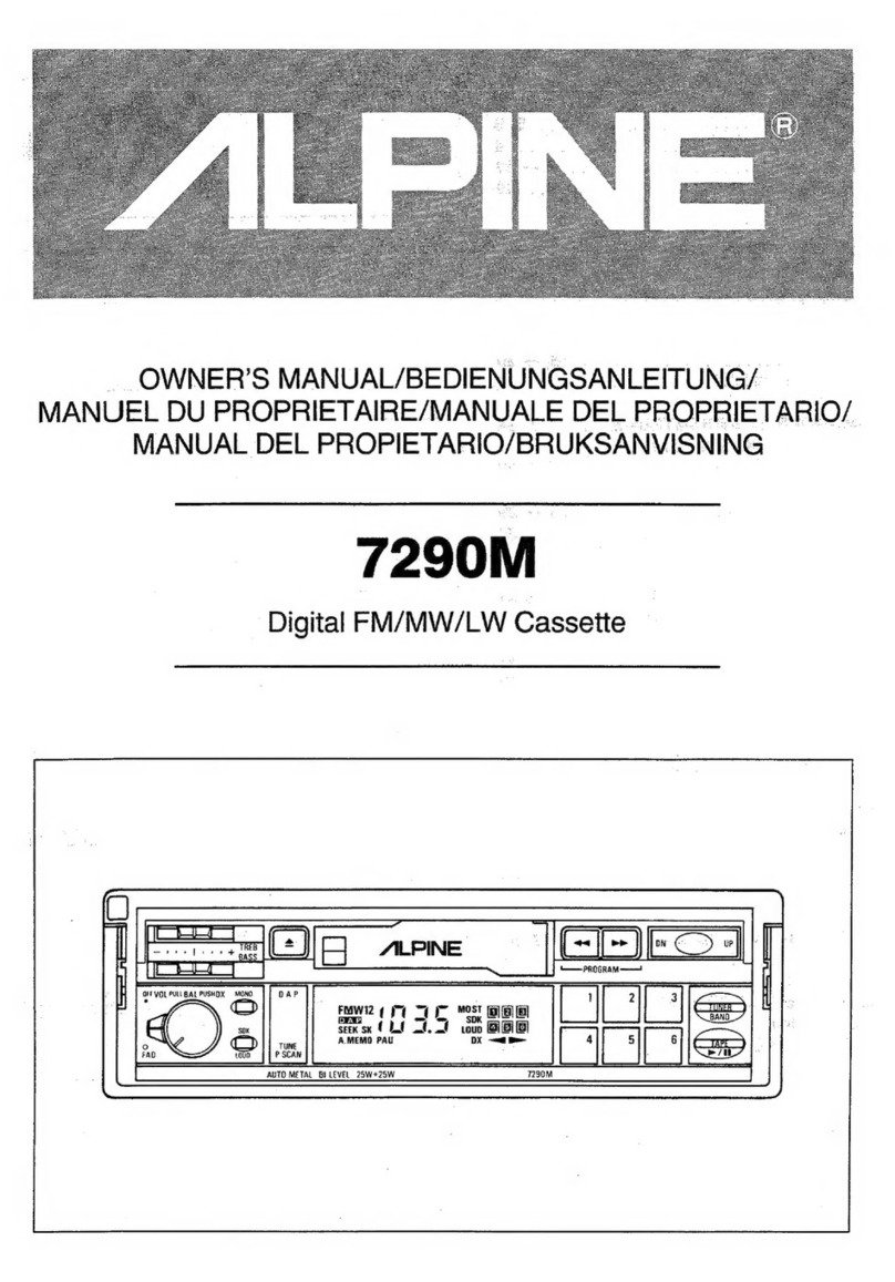
Alpine 7279M User manual

JILPINE
wanvat
Digital
Tuner
Cassette
Jaa
[ERE
=
a
wat”
46
wo
x
LOUD
SK
SOK
—
Pa
|
7279M
“For
the
cassette
deck
mechanism
parts
(GT75B01B,,GT75BO1C)
of
this
model,
refer
to
the
GT
Series
Service
Manual
(Part
No.
68P92539F02).”
Cassette
Deck
Mechanisms
by
Serial
Numbers.
ta
7279M
7279L
7279E
7279M/L/E
Contents
Specifications
ore
rr ec
reece
etree
teen
eee
eee
een
eee
tenet
eee
e
teen
eet
e
neces
ese
terteet
ten
eeeeen
eee
eee
neta
aaas
2
to
3
Controls
&
Indications
-r<
ccc
ec
e
ce
ce
ee
EEE
EE
Ene
eee
nee
e
EEE
EERE
eee
Eee
nnn
EE
ett
Hees
4
Connections
errs
rere
eee
nee
ee
en
ee
een
EERE
Eee
Eee
nen
een
e
ee
EEE
Eee
EEE
ee
eR
Ene
Ente
nee
eee
e
nents
5
Operation
<2
rire
rere
ere
eee
eee
erent
eee
eee
este
eee
r
tt
eceer
reer
ener
e
rere
rene
res
5
to
6
Disassembly
Instructions
scrcc
etc
etter
eee
ene
ett
etter
eee
e
teen
cnt
e
nett
nett
enn
eet
e
eerste
see
en
es
7
to
8
Adjustment
Procedures
«c++
strc
cet ere
eects
tee
e
nee
ee
rete
eee
ete
e
renee
eee
eens
eters
eae
e
nett
eee
eee
enna
teens
9
to
12
Adjustment
Locations
+
+:+rttcretecrc
eect
ee
ene
eee
ee
rete
eee
e
eee
ne
eee
e
eens
e
easter
eeeee
nee
eeen
enter
eee
steed
13
to
15
FM
Tuner
Schematic
Diagram
-cecceset
cree
cece
eee
ree
tees
tee
e
eee
eee
e
nena
eens
eee
e
eee
ee
ener
ernest
reat
eee
eee
eens
16
Block
Diagram
<crcettccce
rete
eter
teen
cette
nee
reece
eee
e
eee
ee
eee
e
nest
enene
een
eeeeaeeeeereneeesene
ree
erares
17
to
18
Parts
Layout
on
P.
C.
Boards
and
Wiring
Diagram
(1/2)
ccrcecce
treet
tte
eet
teen
e
eee eee
ee
sent teen
tees
19
to
21
Parts
Layout
on
P.
C.
Boards
and
Wiring
Diagram
(2/2)
crcrrree
ect
r
eter
erent
erent
ent
eee
ene
ne
ene
erees
22
to
24
Schematic
Diagram
(1/3)
cceccccececec
eects
cence
eres
sees
eneeennee
sence
scenes
sree
reese
ees
ee
ners
senate
anes
25
to
27
Schematic
Diagram
(2/73)
Pre
ar
eae
rer
ee
28
to
30
Schematic
Diagram
(3/3)
<trccceec
cece
stent
ener
nett
eee
eee
etree
ene
n
eee
eee
nena
nee
nee
ne
er
ee
ene
e
es
31
to
32
Electrical
Parts
List
eer
eT
ee
rE
ee
ee
ee
Te
ee
Pe
ee
ee
eRe
ee
rr
er
ee
ey
33
to
42
Packing
Assembly
Parts
List
-:+ccctrec
crc
ece
tec
cec
ences
eee
ee
eens
nee
e
nate
nee
e
eee
ee
nena
ete
a
ents
neste
eneteenees
43
Cabinet
Assembly
Parts
List
<cccctrecrccerre
reece
ener
terete
eee
eee
en
tence
teen
ener
nseen
reer
een
e
sees seer
eeeennnns
44
Exploded
View
(Cabinet)
-ccceetccecc
eee eec
tree
eerste
e
nee
n
neces
nena
eee
e
ee
ee
ene
e
eee
ee
ene
naan
ners nese
nees
45
to
46
Packing
Method
View
«rscrecccecreccee
ees
ee
ee ee
ene
e
eee
ee
erent
neces
eee
e
nee
e
eee
e
eee
eee
ee
nena
eee
ee
enna
eeeneees
46
Semi-conductor
Lead
Identifications
«cccsce
rece
cece
sent
eee
e
eect
eter
neta
een
eee
e
eee
e
tenner
eeeneee
tree
n
ences
47
to
51
s
oe
s
Specifications
FM
RADIO
Intermediate
Frequency
-reccec
eter
cee
c
teeter
ee
teen
ene
e
eee
n
nent
een
e
nee
eee
EE
eee
ee
een
en
eee
Eee
EEE
EEE
Ee
tes
10.7+0.1MHz
Frequency
Range
cccrcse
tree
cette
eee
e
teen
eee
n
eee
eee
teen
ee
een
t
ERE
eee
EERE
eee
a
EEE
EERE
REE
REDE
EEE
ES
87.5
to
108MHz
Usable
Sensitivity
(Stereo
at
O8.1MHz)
vrrcrr
sree
reece
e
teeter
eee
e
ence
ence
ences
19.2dBf
(7279M/L
Models
Only)
17.2dBf
(7279E
Model
Only)
Limiting
Sensitivity
(OB.1MHz)
cerrtce
terre
errr
terete
reece
cence
eee
ete
e
eens
14.2+5dBf
(7279M/L
Models
Only)
S/N
Ratio
(Stereo
60dB
up
QB.1MHZ)
creer
errr
rete
r
tte
etree
eect
nent
e
eee
ees
50dB
(7279M/L
Models
Only)
48dB
(7279E
Model
Only)
Image
Rejection
(at
106.1MHz)
srr
cette
ree
teen
et
ete
terete
eee
ener
eee
n
nn
eee
etn
e
ence
etter
eet
e
ee
eeeernees
40dB
IF
Rejection
(at
GQO.IMHz)
secre
cere
e
eee
rere
renee
een
enn ete
e
eee
n
een
nett
n
ne
cee
nent
ene
ene
nearer
ene
eee ene
60dB
Distortion
(Input
1V
at
98.1MHz)
Poe
ae
ee
aD
1%
Frequency
Response
(Ref.
400HZ)
-rrrtert
rrr
t
rr
eres
tree
e
seer
eee
ener
eeeceees
80Hz:
0+3dB
(7279E
Model
Only)
100Hz:
O0+3dB
(7279M/L
Models
Only)
10kHz:
-—12+3dB
Stereo
Separation
(at
1,000Hz)
ee
meee
eee
ere
ee
mene
rece
near ener
ese
Sede
esas
ath
ss
Heres
eseresereseneeneeeseeesese
25dB
AM
RADIO
(7279E
Model
Only)
Intermediate
Frequency
Cr
rar
aera
a
aa
ee
ee
ee
a
er
re
rr
re
irr
marr
ar
ar
a
rary
450kHz
Frequency
Range
Se
ee
aera
eee
aa
eae
ore
eee
ee
2a
er
531
to
1,602kHz
Sensitivity
20dB
S/N
(at
QOQKHz)
recs
teeter
ete
teen
eee
enna
e
een
n
etn
e
nent
eee
n
en
eet
nena
45.2dBf
SiN
“Ratio
(at
QOOKHZ)
“estevs
laweeeecanaen
Sedeena
dtaslaveatnae
tet
ad
nals
aa4%
Widains
oe
hee
eek
tad
beiees
ohne
44dB
Image
Rejection
Cat
1,404kKHzZ)
creer
errr
rete
terete
eee
e
erent
ence
eee
n
rete
eee
n
eee
n
eee
teense
ene
e
ee
eaetsetnns
44dB
IF’
Rejection:
(at
GOSKHz))
<i
sscesecsedeck
sce
etae
enna
as
cles
aia
a
aed
eee
tt
edieamededied
eine
dees
sbabiigaweeeieledhe
60dB
Distortion
Cat
QGQKHz)
-se
cece
eee
e
eect
ere
c
nett
ete
tee
eee
tenet
Ene
EERE
EEE
REESE
EEE
HOES
EEE
e
EEE
EOE
E
DELETES
2%
Frequency
ReSOpnse
ores
ttre
reece
eee
ee
een
ener
ene
n
een
e
ene
e
enn
ee
nnn
ees
ener
EE
een
REE
EES
100Hz:
-3+5dB
4kHz:
—12+5dB
S29.
7279M/L/E
MW
RADIO
(7279M.‘L
Models
Only)
Intermediate
Frequency
ee
ee
ee
cs
450
+5kHz
Frequency
Range
vers
r
tert eter
er
etree
ete
ee
nee
e
cence
eee
en
eects
eee
teeta
eet
n
tense
tater
ster
esecene
531
to
1,602kHz
Sensitivity
20dB
SAN
Cat
999kHz)
ea
ara
a
rae
45.2dBf
S/N
Ratio
(at
999kHz)
wee
ee
emer
cee
eee
w
eee
n
ewer
eet
O
OO
EEE
Eee
eee
EE
eee
rere
n
aes
eee
sere
rereennanene
44dB
Image
Rejection
(at
1,404kHz)
ea
ee
a
arr
45dB
IF
Rejection
(at
603kHz)
i
ii
i
i
i
i
i
60dB
Distortion
(at
999kHz)
ic
1%
Frequency
Response
ee
er
a
ee
100Hz:
—3+3dB
4kHz:
-—12+6dB
LW
RADIO
(7279M
/L
Models
Only)
Intermediate
Frequency
«cers
ce
eset
etter
etree
eect
eee
n
ene
e
tate
n
esate
eee
e
nee
eee
e
ete
e
test
ensee
teen
cs en
eens
450+5kHz
Frequency
Range
cerctrcc
cers
ce
tcc
e
ett
e
tee
tee
e
eee
e
nen
eet
e
ete
g
essen
eeen
nsec
e
rene
t
ee
ceneeeaee
en
enes
153
to
281kHz
Sensitivity
20dB
S/N
(at
218kHz)
serececeee
reese
eee
ec
neste
et et
eee
ee
eres
ee
renter
nes
48.2dBf
(7279L
Model
Only)
(at
ZIGKHZ)
verre
cette
cree
cent
e
tent
ee
eee
teen
ence
ene
e
reat
ences
48.2dBt
(72798M
Model
Only)
SYN
Ratio
Cat
2ISKHZ)
ccrc
errr
tee
re
teen
eee
e
ene
e
tee
e
een
e
ee en
test
ete
te ee
eaes
40dB
(7279L
Model
Only)
(Cat
QIGKHZ)
creer
cere
tree
eee
eee
e
ene
erent
ete
e
eect
eee
te
seer
tect
eats
40dB
(7279M
Model
Only)
Image
Rejection
(at
272KHz)
cece
cree
ete
ete
e
tenet
eet
eee
eect
ete
e
tence
eter
e
eee
ees
40dB
(7279L
Model
Only)
CAA
LO)
40
2
eer
40dB
(7279M
Model
Only)
IF
Rejection
(Cat
218KHz)
-ccre
cree
eet
e
tee
e
eee
eect
net
e
tee
ence
ee
eet
en
ee en et
en
eer
e
tees
50dB
(7279L
Model
Only)
(at
216kHz)
ee
ee
50dB
(7273M
Mode]
Only)
Distortion
(at
400kHz)
tae
NevGvey
A'S
eis
alee
fa,
6
aS
6 e
nab
lacenereh
ahe.w
eBid
ree
8.
646-8
8.GMEaw:
alle:
0G:
6).
wie
TE
wy
niece
ferare,
8:08
Wiese,
Wigs
Bie
858
oie
8
$2008
Sa
'e
"918
,6)1000,
700:
1.5%
Frequency
Response
ob.
0:
Geter
Siete
sceria
e
Bre
WE
Moe
ere“:
6
acaba
chee
ae
Wielp
868
Ge.
eVe.
Said aera
©
pve
W/eua
eles
are
we
este
8;
676i
B
(Sele
serat
ayes
—3+3dB
(100Hz)
-—12+6dB
(4kHz)
TAPE
PLAYER
Tape
Speed
(MTT-111)
ccccect
cece
ee
ee
tet
tenes
een
e
rete
en
eeeenee
eee
eneeeeeneeeneaees
4.76cm/sec.
+3%
to
-1%
Wow
&
Flutter
CIS,
WRMS/MTT-111)
cccceceecece
eee
e
ee
eee
eee
e
ener
ne
ene
err
e
errr
teen
eee
E
eee EEE EEE
Ee
Ee
0.25%
SN
Ratio
(MTT-112)
ceecce
cette
tere
eee
eee
e
eee
ence
eeeeesenseeeenseneeeeneeeeaes
50dB
(7279M//L
Models
Only)
52dB
(7279E
Model
Only)
Distortion
(MTT-118)
ee
eee
i
ie
ee
rd
2%
Frequency
Response
(Ref.
1kHz,
MTT-256)
csrrcsreceeerreeeeee
63Hz
—3dB
to
10kHz
-—3dB
(7279E
Model
Only)
(Ref.
1kHz,
MTT-356)
srrrrserre
ree
63Hz
—5dB
to
10kHz
—3dB
(7279M/L
Models
Only)
Separation
(MTT-141)
cceccece
reece
ere
e
cece
ere
eee
e
nee
e
teense
eens
eeeene
sent
ener
eee
s
eens
eee
nee
tenet
een
e
eee
enes
30dB
Crosstalk
(MTT-1
21)
Se
a
ee
ee
er
er
os
45dB
FF
&
RWD
Time
(C-60)
a
a
ee
ee
a
a
i
ae
a
er
rd
100
sec.
GENERAL
Load
Impedance
are
area
are
re
ee
ee
eam
m
ea
ccc
ccens
4
ohms
(Speaker
Out)
Power
Supply
PP
err
eer
ee
ee
a
re
ee
i
ee
er
rary
14.4V
DC
Power-Output
(10%
T.H.D)
crrrr
rere
r
rere
etter
rere
t
tere
ree
eee
e
eee
ees
400Hz:
9W/ch
(7279E/M
Models
Only)
1kHz:
9“W/ch
(7279L
Model
Only)
Pre-Output
Voltage
<cccctcre
cree
cece
cree
ete
ee
tenet
eee
teen
ene
e
een
eee
Eten
teen
ee
eee tee
ees
e
tenet
eee
tenn
es
1.2V
Chassis
Dimensions
t++tttttrts
ttre
sree
etree
eesess
178
(W)
X50
(H)
x160
(D)
mm
(7279L/M
Models
Only)
178
(W)
x50
(H)
x153
(D)
mm
(7279E
Model
Only)
Nose
Dimensions
<vrrrttr
rts
tt
rrr
rr
sree
reste
rere
eeeees
176
(W)
x50
(H)
x11
(D)
mm
(7279M/L
Models
Only)
171
(W)
x48
(H)
x15mm
(7279E
Model
Only)
Semiconductors
srrrssrts
ests
reece
9
IC’s,
32
Transistors,
42
Diodes,
10
Zener
Diodes,
1
IFT
(7279E
Model
Only)
12
IC’s,
43
Transistors,
49
Diodes,
13
Zener
Diodes,
1
IFT
(7279M
Model
Only)
16
IC’s,
33
Transistors,
40
Diodes,
13
Zener
Diodes,
1
IFT
(72791
Model
Only)
Weight
BORN
Seeded
NSLS
ew
Bow
Bier
ane
eerie
eral
ere,
ele
le
S70,
8-6.b
Wye
ob 0%
aie
0.
eel
ele
ea
laters
Sele
els.
b
a18'R
Mie
e
Ae
i
ayanes
2
We
aidie
1.7kg
(7279M/4L
Models
Only)
1.8kg
(7279E
Model
Only)
NOTE:
Due
to
continuing
product
improvement,
specifications
and
designs
are
subject
to
change
without
notice.
T279M/L/E
CONTROLS
&
INDICATORS
a)
@)
@®
BASS
Control
@
TREBle
Control
@®
EJECT
Switch
@
Radio
Band
Indicator
©
Frequency
Indicator
Cassette
Loading
Slot
Memory
indicator
Preset
Channel
indicator
Tape
Direction
Indicator
FM
Stereo
Reception
Indicator
(ST)
PROGRAM/FF
&
REW
Switches
Tuning
(DN)
Switch
Tuning
(UP)
Switch
SEEK
TUNE
Switch
BAND
Select
Switch
18
Station
Preset
Switches
BEOeE0®@
)
8
eee
5)
6)
7279M
model
SS
SSS
==
SS
ts
SE,
2)
2dadda
a
(16)
(E)
i)
7279L
model
7279E
model
@
Monaural
Indicator
(MQ)
@
SDK
Indicator
(7279M
model
only)
SK
Indicator
(7279M
model
only)
@
LOUDness
Indicator
@)
DX
(Local/Distance)
Indicator
@
SEEK
Tuning
Indicator
@
Monaural
Switch
(MONO)
@
SDK/LOUDness**
Switch
(7279M
model
only)
@
MEMOry
Switch
@
DX
(Local/Distance)
Switch
@
Power
on/OFF
Switch/VOLume
Control/BALance
Con-
-
trol
(Pull)
@
FADer
Control
9
Radio
Monitor
Indicator
(R.MONI)
(7279L/E
models
only)
4)
R.MONI/LOUDness**
Switch
7279L/E
models
only)
CONNECTIONS
OPERATION
——_
«Antenna
Receptacle
=
———
ES)
White/Black
a
.
Left
Speaker
Output
Lead
common)
—
ee,
Gray/Black
aoe
=
Right
Speaker
Output
Lead
{common}
ne
Left
Front
Speaker
Output
Lead
|
Whrte
_
——
eS)
Right
Front
Speaker
Output
Lead
Grey
—
SE
CES
Left
Rear
Speaker
Output
Lead
|
Green
—_—
eS
Right
Rear
Speaker
Output
Lead
Blue/Whre
—_
Remote
ON
Lead
Red
—
fae
©
ACC
Power
Lead
—s
Lc
ee
Baiery
lesa
Ground
Lead
ist
id
‘TAPE
PLAYER
OPERATION>
1.
Turn
the
power
on
by
rotating
the
VOLume
control/power
switch
@
clockwise.
With
the
tapa
opening
to
the
right,
in-
sert
the
cassette
into
the
loading
slot
as
far
as
it
will
go.
One
of
the
tape
direction
indicators
@
will
light
and
the
tape
will
Start
playing.
If
a
metal
or
CrO,
cassette
tape
is
inserted,
the
tape
mecha-
nism
automatically
sets
itself
for
70ssec
equalization.
Adjust
VOLume
@,
BASS
@,
TREBle
@,
BALance
4
and
FADer
2
controls
to
suit
your
listening
preference.
Tape
re-
verses
automatically
at
the
end
of
the
tape
to
play
the
other
side.
Tochange
from
side
A
to
play
side
B
or
vice
versa
before
the
end
of
the
tape
is
reached,
press
the
PROGRAM
switch
4).
To
stop
tape
play,
press
the
EJECT
switch
®.
Toturn
the
power
OFF,
fully
rotate
the
VOLume
control
coun-
terclockwise.
Winding
the
Tape
Rapidly
in
Forward
or
Reverse
Direction
dh
2
3.
Press
the
PROGRAM
Switch
(
44
or
»»
button)
6)
until
it
locks
and
the
tape
will
run
rapidly
in
the
designated
direction.
Lightly
press
the
other
button
to
stop.
the
Fast
Winding
mode.
The
tape
will
start
playing
again.
When
the
Fast
Winding
operation
reaches
the
end
of
the
tape,
the
mode
will
automatically
switch
to
playback.
AUTO
PAUSE
When
the
unit
is
removed
from
its
bracket,
it
automatically
goes
into
the
Tape
Pause
Mode,
the
tape
disengages
from
the
cap-
stan
and
pinch
roller.
When
the
unit
is
re-inserted
into
the
brack-
et,
tape
play
will
resume
from
the
point
in
which
it
was
stopped.
Key-off
Pause
If
the
ignition
is
turned
off
while
a
cassette
is
playing,
the
tape
disengaqas
from
the
tapa
head,
capstan,
and
pinch
roller,
but
the
cassette
remains
in
the
cassette
compartment
with
the
cas-
sette
door
completely
closed.
When
the
ignition
switch
is
turned
on
again,
playback
will
begin
from
the
point
where
it
was
left
off.
i
Violet
_
Right
5
Red
Output
RCA
Type
Connector
Left
White
Blue
Power
Antenna
Lead
727T9M/L/E
Output
RCA
Type
connectors
RCA
type
connectors
are
for
connecting
the
unit
to
an
unit
having
RCA
type
input
terminals.
Power
Antenna
Lead
Connect
the
power
antenna
control
lead
(Blue)
to
the
connector
of
full
automatic
power
antenna.
Power
antenna
control
does
not
work
with
semi-automatic
or
manually operated
antenna.
ACC
Power
Lead
This
lead
is
to
be
connected
to
an
ignition
terminal
in
the
vehicle’s
fuse
box
or
a
terminal
which
develops
+
12
V
when
the
ignition
is
turned
on.
Remote
ON
Lead
If
the
unit
is
connected
to
your
Amp
unit
with
RCA
jacks,
connect
the
remote
ON
lead
to
the
male
con-
nector
of
the
unit
remote
ON
lead.
CAUTION:
Before
connecting
any
wire,
set
the
volume
level
to
minimum
by
turning
the
power
ON/OFF
switch
knob
counterclockwise.
Radio
Monitor
(7279L/E
models
only)
Pushing
the
RADIO
MONITOR/LOUDNESS
switch
@,
Radio
Monitor
is
activated
and
R
MONI
indicator
@
will
light,
you
can
receive
the
last
tuned
station
or
operate
seek
tuning
UP
@3
and
DOWN
42.
Push
this
switch
for
3
seconds
or
more
to
activate
LOUDNESS
function;
LOUD
indicator
lights
up.
Low
frequency
sound
will
be
boosted
at
low
sound
contents.
Push
the
switch
again
for
3
seconds
or
more
to
release
the
function.
«RADIO
OPERATION»
MANUAL
and
AUTOMATIC
SEEK
TUNING
(7279M/L
models
only)
The
radio
does
not
operate
in
the
tape
play
mode.
Tolisten
to
the
radio,
eject
the
cassette
by
pressing
the
EJECT
switch
@).
Pressing
the
EJECT
switch
®
during
tape
play
causes
the
tape
in
the
loading
slot
to
be
ejected.
1.
Turn
on
the
power
by
turning
the
VOLume
control/Power
OFF
switch
@
clockwise.
Continue
to
rotate
it
until
the
de-
sired
volume
level
is
reached.
2..
Push
Radio
BAND
select
switch
@®
for
reception
of
MW/LW
or
FM
(FM
1
or
FM2).
The
radio
BAND
Indicator
@
will
be
on,
and
the
ST
[stereo]
indicator
@
will
also
be
on
during
FM
stereo
reception.
3.
Adjust
BASS
©,
TREBle
@,
BALance
@,
and
FADer
@
con-
trols
to
their
center
positions.
4.
To
automatically
tune,
press
the
SEEK
TUNE
button
19
and
then
either
UP
or
DN
tuning
button.
The
SEEK
indicator
@
ap-
pears
on
the
display
and
the
frequency
changes
to
indicate
that
the
radio
is in
the
auto
SEEK
tuning
mode
and
ready
to
stop
at
every
strong
station.
Repeat
the
procedure
until
your
desired
station
is
obtained.
When
the
radio
reaches
the
up-
per
or
lower
end
of
the
band,
it
automatically
starts
scanning
in
the
opposite
direction.
To
return
to
manual
tuning,
press
the
SEEK
TUNE
button
again,
the
SEEK
indicator
disappears.
5.
Tomanually
tune,
press
the
Tuning
Switch
(UP)
43
for
higher
frequency
broadcasts,
and
press
the
Tuning
Switch
(DN)
for
lower
frequency
broadcasts.
Sabi
-7279M/LYE
6.
Adjust
VOLume
22,
BASS
“D,
TREBle
©,
BALance
2”,
and
FADer
28,
to
suit
your
listening
preference.
7.
To
switch
from
FM
to
MW/LW
or
vice
versa
press
the
BAND
select
switch
1.
Memory
Operation
(7279M/L
models
only)
1.
Select
FM1, FM2,
or
MW/LW
by
pressing
the
BAND
select
switch
49.
2.
Select
a
station
manually
or
by
SEEK
tuning.
3.
Press
the
MEMOry
switch
2.
The
memory
indicator
@
will
light.
4.
Press
a
Station
Preset
switch
to
preset
the
station
in
MEMO-
RY.
5.
Repeat
steps
2,
3
and
4
to
preset
up
to
6
stations
per
band
(FM1,
FM2
or
MW/LW)
total
24
stations.
Press
one
of
the
unused
Station
Preset
switches
48
each
time.
6.
Press
the
Radio
Band
select
switch
@
to
preset
six
stations
on
another
band.
Follow
Steps
2,
3,
4,
and
5.
Remember,
there
are
altogether
four
(FM1,
FM2,
and
MW/LW)
bands.
7.
To
tune
in
a
frequency
programmed
into
memory,
press
the
desired
station
preset
switch,
1
through
6.
If
the
radio
is
set
to
MW/LW,
you'll
receive
an
MW/LW
frequency.
If
in
the
FM
mode,
you'll
receive
an
FM.
8.
Adjust
VOLume
4,
BASS
@,
TREBle
@,
BALance
@,
and
FADer
48,
to
suit
your
listening
preference.
MANUAL
and
AUTOMATIC
SEEK
TUNING
(7279E
model
only)
The
radio
does
not
operate
in
the
tape
play
mode.
To
listen
to
the
ra-
dio,
eject
the
cassette
by
pressing
the
EJECT
switch
®.
1.
Turn
on
the
power
by
turning
the
VOLume
control/Power
OFF
switch
@
clockwise.
Continue
to
rotate
it
until
the
desired
vo-
lume
level
is
reached.
2.
Push
Radio
BAND
select
switch
@
for
reception
of
AM
or
FM
(FM
1
or
FM2).
The
radio
band
Indicator
®
will
be
on,
and
the
ST
[stereo]
indicator
(
will
also
be
on
during
FM
stereo
reception.
3.
Adjust
BASS
©,
TREBle
@,
BALance
@,
and
FADer
@
controls
to
their
center
positions.
4.
To
automatically
tune,
press
the
SEEK
TUNE
button
@
and
then
either
UP
or
DN
tuning
button.
The
SEEK
indicator
@
appears
on
the
display
and
the
frequency
changes
to
indicate
that
the
radio
is
in
the
auto
SEEK
tuning
mode
and
ready
to
stop
at
every
strong
Station.
Press
the
tuning
button
until
your
desired
station
is
ob-
tained.
When
the
radio
reaches
the
upper
of
lower
end
of
the
band,
it
automatically
starts
scanning
in
the
opposite
direction.
To
return
to
manual
tuning,
press
the
SEEK
TUNE
button
again,
the
SEEK
indicator
disappears.
5.
To
manually
tune,
press
the
Tuning
Switch
(UP)@
for
higher
fre-
quency
broadcasts,
and
press
the
Tuning
Switch
(DN)
@2
for
low-
er
frequency
broadcasts.
6.
Adjust
VOLume@,
BASS
©,
TREBle
@,
BALance
@,
and
FADer
@,
to
suit
your
listening
preference.
7.
To
switch
from
FM
to
AM
or
vice
versa
press
the
BAND
select
switch
@.
Memory
Operation
(7279E
model
only)
1.
Select
FM1,
FM2,
or
AM
by
pressing
the
BAND
select
switch
@.
2.
Select
a
station
manually
or
by
SEEK
tuning.
3.
Press
the
MEMOry
switch
@.
The
memory
indicator
will
light.
4.
Press
a
Station
Preset
switch
to
preset
the
station
in
MEMORY.
5.
Repeat
steps
2,
3
and
4
to
preset
up
to
6
stations
per
band
(FM1,
FM2
or
AM)
total
18
stations.
Press
one
of
the
unused
Station
Preset
switches
4
each
time.
6.
Press
the
Radio
Band
select
switch
@
to
preset
six
stations
on
another
band.
Follow
Steps
2,
3,
4,
and5.
Remember,
there
are
altogether
three
(FM1,
FM2,
and
AM)
bands.
7.
To
tune
ina
frequency
programmed
into
memory,
press
the
de-
sired
station
preset
switch,
1
through
6.
if
the
radio
is
set
to
AM,
you
Il
receive
an
AM
frequency.
If
in
the
FM
mode,
you’
llreceive
an
FM.
8.
Adjust
VOLume@,
BASS
®,
TREBle
D,
BALance
@,
and
FADer
@,
to
suit
your
listening
preference.
FM
STEREO/MONAURAL
Selection
(MONO
Switch}
During
stereo
reception,
should
the
signal
level
become
weak
(the
“ST”
indicator
40
in
the
display
blinks),
select
monaural
re-
ception
by
pressing
the
MONO
switch
@
to
decrease
noise
le-
vel.
NOTE:
Monaural
mode
has
been
setinitially.
Push
the
MONO
switch
23
when
a
stereo
broadcast
is
being
received.
Local/Distance
Switch
Operation
You
may
select
local
or
distance
mode
during
SEEK
tuning
When
it
is
in
the
local
mode
(Distance
(DX)
indicator
4?
is
off),
it
allows
you
to
tune
in
strong
signal
stations
only
(stutions
C,
F,
H
and
L
as
shown
below).
When
it
is
in
the
distance
mode
(Dis-
tance
(DX)
indicator
ts
on),
weak
and
strong
signal
stations
(stations
from
A
through
M)
will
be
tuned
in.
Once
a
station
is
tuned
in
by
SEEK
in
local
mode,
the
mode
will
automatically
switch
to
distance
mode
for
optimum
reception.
Signal
strength
=>
ao
Frequency
NOTE:
Dx
(Local/Distance)
Switch
28
functions
only
in
SEEK
tuning.
Traffic
Information
Receiving
(7279M
model
only)
This
model
is
equipped
with
traffic
information
receiving
appara-
tus
to
be
used
in
West
Germany
where
the
traffic
information
is
broadcast
in
FM.
The
following
is
how
to
use
this
unit
to
receive
traffic
information
broadcasting.
1.
Select
FM
position.
2.
Depress
the
SDK
switch
and
tune
toa
Station.
If
the
station
is
a
traffic
information
station,
the
SK
indicator
will
glow
and
show
the
reception
of
a
broadcast
from
a
traffic
information
station.
NOTE:
SK
Indicator
When
SK
signal
is
received
irrespective
of
the
SDK
position,
the
SK
indicator
will
illuminate.
3.
In
the
SDK
mode,
stations
other
than
traffic
information
stations
are
muted
and
cut
out.
Therefore,
itis
easy
to
select
a
traffic
information
station.
4.
As
the
signal
of
the
tuned
traffic
information
station
becomes
weak,
the
SK
indicator
will
extinguish,
then
after
the
lapse
of
30
seconds,
a
rhythmical
alarm
will
sound
to
urge
retuning
to
another
stronger
Station.
If
the
reception
of
further
traffic
in-
formation
is
required,
tune
in
the
desired
traffic
information
Station.
When
received,
the
alarm
will
stop
and
the
SK
indi-
cator
illuminates.
Since
the
alarm
will
continue
if
no
signals
from
any
other
traffic
stations
can
be
received,
release
SDK
switch
for
the
reception
of
normal
broadcasting.
5.
When
the
unit
is
playing
a
cassette
tape
with
the
SDK
switch
pushed
in
and
tuned
to
a
traffic
information
station,
the
tape
play
is
interrupted
and
changed
to
FM
radio
if
the
pre-tuned
Station
begins
a
traffic
information
message.
When
the
message
is
over,
the
unit
reverts
to
tape
play
automatically.
6.
Even
if
the
VOLUME
control
is
set
to
the
minimum
position,
the
volume
of
the
traffic
information
will
be
automatically
ad-
justed
to
proper
level.
After
the
message,
the
sound
volume
returns
to
the
previously
adjusted
level.
7.
If
traffic
information
reception
is
no
longer
necessary,
re-
lease
SDK
switch
for
normal
radio
reception.
727M
/“L/E
Disassembly
Instructions
1.
Removal
of
Nosepiece
(1)
After
removal
of
bracket
handle,
top
cover
and
bottom
cover,
remove
two
control
knobs
(Volume,
(Top
Slide)
Balance)
and
two
slide
knobs
as
shown
in
Figure
1.
(2)
Remove
two
screws
marked
“O”
and
two
hooks
(A)
as
shown
in
Figures
1
and
2.
(Bottom
Side)
Nosepiece
Slide
Knobs
Nosepiece
Control
Knobs
(Volume,
Balance)
Figure
1
Figure
2
Hook
(A)
2.
Removal
of
Cassette
Deck
(1)
After
removal
of
nosepiece,
remove
four
screws
marked
“xX”
as
shown
in
Figures
1
and
3.
(2)
Disconnect
one
connector
from
the
cassette
deck.
x
SDK
P.
C.
Board
(7279M
Model
Only)
Switching
P.
C.
Board
Cassette
Deck
(7279L
Model
Only)
T
aoGs
Tone
P.
C.
Board
uner
P.
C.
Board
(7278M/L
Models
Only)
Figure
3
3.
Removal
of
Front
P.
C.
Board
(1)
After
removal
of
cassette
deck,
remove
two
screws
marked
“O”
as
shown
in
Figure
4.
(2)
Remove
the
solder
(c)
as
shown
in
Figure
6.
(3)
Disconnect
one
wire
from
the
Front
P. C.
Board.
Note
:Do
not
cut
parallel
wires
from
the
Main
P.
C.
Board
by
removing
the
solder
(c).
Nut
©
Figure
4
|
727T9M/L/E
4.
Removal
of
Tuner
P.
C.
Board
(1)
Remove
the
solder
(b)
as
shown
in
Figure
6.
5.
Removal
of
Tone
P.
C.
Board
(7279M//L
Models
Only)
(1)
After
removal
of
cassette
deck,
remove
the
solder
(d)
as
shown
in
Figure
6.
(2)
Disconnect
two
connectors
from
the
Tone
P.
C.
Board.
6.
Removal
of
SDK
P;
CG.
Board
(7279M
Model
Only)
(1)
Remove
the
solder
(e)
and
(f)
as
shown
in
Figure
6.
Rear
Chassis
A
QRB
Connector
(Socket)
7.
Removal
of
Swithching
P.
C.
Board
(7279L
Model
Only)
Figure
5
(1)
Remove
the
solder
(f)
as
shown
in
Figure
6.
Hook
(B)
Solder
(a)
Hook
(B)
Solder
(e)
(7279M
Model
Only)
Solder
(a)
(7279M/L
Models
Only)
Solder
(b)
r
ae
a
k
Tig
pee
Paths
—
Main
P.
C.
Board
Solder
(f)
fa
hs
ae
tit
(7279M//L
Models
Only)
Tony
“ne
ees
Bie
R
yo
eae
mor
—
“Oris
YY
sega
Solder
(d)
Solder
(b)
(7279M/L
Models
Only)
Front
P.
C.
Board
Solder
(c)
8.
Removal
of
Main
P.
C.
Board
Pataller,
wyres
Figure
6
(1)-1
After
removals
of
Front
P.
C.
Board
and
Tuner
P.
C.
Board,
remove
the
solder
(a)
as
shown
in
Figure
6.
(7279E
Model
Only)
(1)-2
After
removals
of
Front
P.
C.
Board,
Tuner
P.
C.
Board,
Tone
P.
C.
Board
SDK
P.
C.
Board,
remove
the
soder
(a)
as
shown
in
Figure
6.
(7279M
Model
Only)
(1)-3
After
removals
of
Front
P.
C.
Board,
Tuner
P.
C.
Board,
Tone
P.
C.
Board
and
Switching
P.
C.
Board,
remove
the
solder
(a)
as
shown
in
Figure
6.
(7279L
Model
Only)
(2)
Remove
a
nut
and
two
hooks
(8)
as
shown
in
Figure
4
and
6.
(3)
Remove
five
screws
marked
“A”
as
shown
in
Figure
5
and
6.
(4)
Disconnect
all
wires
from
the
Main
P.
C.
Board,
rere
Adjustment
Procedures
1.
AM
SECTION
(1)
Dummy
Antenna
Circuit
1
Input
'
65pF
:
Output
|
:
1
1
r3
|
es
a
For
50
ohms
AM
Signal
Generator
Figure
7
(2)
Connections
Antenna
Receptacle
AC
Voltmeter
AM
Signal
Generator
AM
Dummy
Antenna
Unit
Under
Test
Figure
8
DC
Digital
Figure
9
Unit
Under
Test
Voltmeter
(3)
Location
of
Adjustment
Parts
See
Adjustment
Locations.
(4)
Control
Settings
Power
Switch
-cecccrce
tre
rect
e
eee
eet
eees
ON
Balance
Control
----:s+err
eres
Mechanical
Center
FMZAM
Switch
vrrtre
reser
e
eter
e
ere
cece
eee
e
es
AM
Treble/Bass
Control
-++++++++--
Mechanical
Center
Others
ec
i
ee
a
a
er
ee
ee
OFF
Fader
Control
pee
n
reer
reese
eres
coencs
Front
Position
(5)
Adjustment
Procedures
(7279E
Model
Only)
i
rl
Si
Co
oo
ps
[eee
me]
|
ome
[Tome
[ewe
|
nomen
|
oom
[RT
em
[mie
ewe]
wire
'
7279M/L/E
(5}
Adjustment
Procedures
(7279ML
Models
Only)
a
2.
SDK
Section
(7279M
Model
Only)
(1)
Dummy
Antenna
ed
For
50
ohms
FM
Signal
Generator
Figure
10
(2)
Connections
DC
Voltmeter
Antenna
Receptacle
FM
Signal
Generator
Antenna
Figure
11
(3)
Control
Settings
Power
Switch
crrssssser
sets
s
ete
cece
e
cece eens
ON
Treble/Bass
Controls
----+:+---
Mechanical
Center
Band
Select
Switch
-cccececeec
ese
cee
reese
eees
SDK
Fader
Control
«sreseererec
eect
eeees
Front
Position
Balance
Control
---++++erse
seers
Mechanical
Center
Other:
2550s
le
Savi
one
tales
ela
since
oD
OFF
(4)
Adjustment
Procedures
Signal
Generator
Dial
Control
Adjustment
7
ee
DK
Adjustment
98.1MHz,
20dB
zu
(SK,
BK:
ON
DK:
OFF)
L601
for
Maximum
Output
of
T.P.10.
98.1MHz
98.1MHz,
66dB
u
(SK,
BK,
DK
:
ON)
VR601
for
Maximum
Output
of
T.Ps11.
98.1MHz
—10—
7279M/L/E
3.
FM
SECTION
(1)
Dummy
Antenna
Circuit
To
ohms
45
‘ohms!
1
Input
!
60
ohms
Output
1
1
bt
St
goes
a
For
50
ohms
FM
Signal
Generator
Figure
12
(2)
Connections
Antenna
Receptacle
DC
Voltmeter
FM
Signal
Generator
}
FM
Dummy
Antenna
AC
VTVM
=
Unit
Under
Test
Figure
13
Antenna
Receptacle
FM
Signal
Generator
FM
Dummy
Antenna
FM
Stereo
=>
=
Unit
Under
test
Oscilloscope
Modulator
;
Figure
14
AC
VTVM
Antenna
Receptacle
ieee
FM
Dummy
°
II
Antenna
FM
Stereo
Modulator
Unit
Under
Test
Figure
15
FM
Signal
Generator
Antenna
Receptacle
FM
Dummy
Antenna
Ground
=
Unit
Under
Test
Figure
16
Antenna
Receptacle
Ground
Unit
Under
Test
(7279E
Model
Only)
Figure
17
(3)
Location
of
Adjustment
Parts
See
Adjustment
Locations.
—-11—
|
7279M/L/E
(4)
Control
Settings
Power
Switch
-rrrrrrcctsr
tress
erect
sees
ecees
ON
Balance
Control
-++++++++s+eeeee-
Mechanical
Center
FM/AM
Switch
corres
rset
reste
eters
eter
eec cee
FM
Treble/Bass
Control
---+++-++--
Mechanical
Center
Others
ccc
c
cree
sree
sere
ete
eee
c
eee
cece
nee
OFF
Fader
Control
«ccc
ce
teeter
cree
reece
Front
Position
VR4
(7279E),
VRS
(7279M/L)
for
minimum
at
L
(R)
channel
output.
Adjust
VR2
for
the
waveform
changing
from
Low
to
High.
98.1MHz,
66dB
zu
Confirm
to
receiving
signal.
: :
T2
(7279E),
T4
(7279M/L)
1
IF
Adjustment
Figure
13
98.1MHz
for
OV+0.03V
between
T.P3
and
4.
(Mono
Signal,
:
L
Signal
for
842dB
Separation.
Seek
Stop
;
.1MH
Adjustment
eS.iMbis
98.1MHz,
66dB
u
(Mod.
400Hz,
G
(Mono
Signal,
2
VCO
Adjustment
Figure
16
98.1MHz
VR3
for
19+0.2kHz
curve
at
No
Modulation)
98.1MHz,
20dB
u
ce
|
eee
ae
Noise
Level
Dev.
22.5kHz)
put
(5)
Adjustment
Procedures
No
Modulation)
98.1MHz,
66dB
u
T.P.5.
Separation
:
98.1MHz,
66dB
»,
1,000Hz
Adjustment
AL):
Signal,
Modulgtion:
|.
22°!
Mh?
VR201-1,
2
(7279E)
ara
eedee
98.1MHz
|
VR302-1,
2
(7279M//L)
FM
Stereo
Blend
Figure
15
igna
(VOLUME)
for
2V
at
Lch.
output.
Adjustment
98.1MHz,
46dB
p
98.1MHz
VR1
(7279E),
VR4
(7279M/L)
Mono
Signal,
No
Modulation
Adjustment
98.1MHz,
—10dB
u
=
=
(Mod.
400Hz
98.1MHz
VR1
for
-25
to
—35dB
at
Lch
Dev.
22.5kHz)
output
*KSteop
Geeess
7279M/L
Model
Only.
Figure
14
4.
TAPE
SECTION
AC
Voltmeter
(1)
Connection
Test
Tape
Unit
Under
Test
(2)
Location
of
Adjustment
parts
Figure
18
See
Adjustment
Locations
(3)
Control
Settings
Power
Switch
<scrcsctrrcr
reer
rrr
tr
cere
reser
ON
Treble/Bass
Control
«+++++++++>
Mechanical
Center
Fader
Control
Periyar
er
arr
ar
rarer
ae
Front
Position
Others
TREE
Ee
OR
ee
eC
ee
RR
OFF
Balance
Control
-sr++sssteeeeeeee
Mechanical
Center
(4)
Adjustment
Procedures
Test
Tape
Test
Point
|
Adjustment
Point
Adjustment
1
Head
Azimuth
|
MTT-114NB
;
Head
Azimuth
Adjust
for
maximum
and
same
:
Figure
18
Adjustment
Screw
|
level
output
at
normal
and
Adjustment
(14kHz)
(Figure
19)
reverse
positions.
MTT-111
i
18
Tape
Speed
Adjustment
Volume}
3,030—3,080Hz
(Figure
20)
Tape
Speed
Adjustment
—12-—-
Adjustment
Locations
Playback
head
Head
azimuth
ajustment
screws
Figure
19
SDK
P.
C.
Board
(Top
View)
(7279M
Model
Only)
—~13-
Tape
speed
adjustment
Figure
20
Tone
P.
C.
Board
(Top
View)
(7279M/L
Models
Only)
7T278M/L/E
Motor
7279M/L/E
=
(Top
View)
.
Board
(7279E
Model
Only)
Cc
in
P
Ma
~14—
|
7279M/L/E
180k
ohms
Tuner
P.
C.
Board
(Top
View)
(7279
Model
Only)
Radio
P.
C
Board
(Top
View)
(7279M/L
Models
Only)
180k
ohms
~15—
T2TIM/L/E|
FM
Tuner
Schematic
Diagram
(7279M/L
Models
Only)
Lo/ox
(3)
%&
R2002
100K
12001
C2009]
C2010
CCF
2001
820
CoO
O®
c2010
2018
Samm
S
amt
4
em
3)
2)
1)
)m9)
-
‘i
Fara
c2025
|
R2010
2
.01
100P
J
1SV6Bor
C2011
O01
2.2K
100
0.01
1SV110
0.014
R2014
C2012
100P
+
x
GZ
C2020
tO
02003
C2014
2015
C2016
474
R2002
*%
1Sv68
3
1
1SP
fy
oe
pre
1a0e
c201
or
3p}
fisviie
|.
2006
NOTE:
PARTS
MARKED
*
ARE
FOR
ADJUSTMENT.
~16—
(6)
F
OUT
(8)
IF
OUT
t—@)
IF
OUT
R2011
C2021
7279M/L/E
(7279M/L
Models
Only)
Block
Diagram
a+3dvl
HOLIMS
(nd)
A34/804
sees
AG
(NI—AR*}
ONIHILIMS
o
\o
HOLIMS
ono
ONIHILIMS
SO1VNY
ON)
A38
A3u
Y4o4
W130"
oO
Au3aLLVa
O
AzE!
SNIHDLIMS
mz.
4
NOILINDECHO
O
A3¥
/
403
aay
Aluo
WEL2L
sak
ax
Ox
?
(40S
Wy
Wd
“3dvL)
dW
310W34
©
\
03
ANY
6
8+3dVi
XISLVW
advi
x:
4
waMod
ABW
97
O
4
y
HOLIAS
\
YOLOW
(w)
@
ainn
|
Av
ids
Hos!
ay
oF
¥
ainw
430
Y3M0d
a
SS¥d
MOT
ONIHDLIMS
xa/0t
i
x0/01
43710481N09
310"
wRAIUC
Y3AZISSHLNAS
NI
WOVd
3a1nW
Vid
WY/W2
O
©
ads
O
@
44dsO
any
@
sv
dsoO
¥aMOd
ONIHOLIMS
TOYLNOD
O
Oras
O
@®
+1480
dW¥
morte
@®
#1dsoO
adie
4aMOd
YOLVE
VINOD
7OYINOD
RELIES
was
ONIHOLIMS
emleon
ome
3AN10A
1041NO9
yas
3WNIOA
HOS
SNIHILIMS
dOlS
OLNV
ON!
‘1S
SNIHILIMS
xd
/
07
H34
(G
O
3ud
vei
=
dA
|
TOdLNOD
1308
is
dwv
4I
8
WY
4
3WNIOA
aNOL
SSv8/3183uL
ut]
dWY
4ING
ODA/XIW
du
11
anal
|
|
319v1d3934
Eh
:
a
ett
a
eas
eel
VNN3INY
{1
34)
ONALNOMd
W4
47s
pee
7279M/L/ZE
Block
Diagram
(7279€
Mode!
only)
AS
G+
3d¥L
avai
°)
QNnoud
43ZITI8¥LS
.
HOLIMS
39VLIOA
1H
Sy
A3U/
404
ova
AUBLIVE
O
AGE!
HOLIMS
Wi3W
Jo
Avi
CNV
m4
‘3d¥L)
av37,
NOILINS!
@+
ONIHDLIMS
HOLIMS
NI
-
Aa»
¥3M0d
Ty
JLAW
19
ALONIY
Oo
Shady
gva,
Y
¥
A
WNNZLNY
Y3M0d
XIMLVN
Aan
(1OStQH
)
rh
ainw
HOLIMS
ee
YOLON
(Ww)
ANO
WOVe
INOW‘
3L0N
=x
y3a1id
Jd0'NO!
S$Vd
MOT
SNIHILIMS
xa/01
QION310S
3LNW
AW1d
Nt
WOWd
¥3TNOYeLNOD
AY
asia
UAZISAHLNAS
SWS
Tid
WW/NS
@
¥u-ds
©
uaavd
dWV
@
4a-ds
0
43M0d
uaMOd
olava
WW
tty
OQ
1-ds
HOLIMS
31nw
HOLIMS
@®
s1-dso
yzav4
dWv
y3A14O
®
i-aso
43
MOd
4amod
310"
HOLIMS
xa/01
ONILAW
HOLIMS
“ano?
ONILAW
B3A1G
HOLIMS
dOLS
SS3N0N01
On
ONIHOLIMS
x0/01
HUG
dW¥
Ea
1OULNOD
XdN
8
dW¥
ssva
UN
130
8
anid
dWV
318
=i)
aonviva
|
|
Swor
|_|
aay]
I}
xgtoo
(|
|
2
|
Yossauans
dWv
4
WA
TEN
au
Ob
dWy
BNIIOA
3SI0N
|
i
H21Q)
en
a
Fy
ri
L
‘i
379¥1d393Y
erry
eet
tee
PRE
WNNGLNY
(t33)
GN3
LNO’S
WA
19
-=
Parts
Layout
on
P.C.
Boards
and
Wiring
Diagram
(1/2)
©7279M.“L
Models
Only
7279L
Mode
mm.
Ayl=
HT
ve
PTitttttttttd
Fy
Lene
1OtH2
ass
st
Pune?
Main
PC.Board
al
soles
ot
od
Poe
ake
|
Cee
ete
|)
J
AU
yg
LI
a
if
:
:
-Ai
-A}
Motor(MISOI)
|
*
GT
Control
PC.Boara
..
GT
Control
PC.Board
72791
Model
(After
80510124
7279M
Model
(
After
80511501
=
7279L
Model
(
Before
80510123)
7279M
Model
(
Before
80511500)
c'15
carson:
+)
:
Flees
beae
ee
PC.
Board
Front
i
%,
fois'a]
ic
S
rapt
2
PE:
es].
2s
mean
mn
988
‘gece,
|
gee
Wy
NT
eee!
233
238
tial
ED
Sy
NX
ae
lll
:
ro
hy
20619
)
106131
Nail
18
oo
Ve
73
hq
£
8
a
roa)
z5
0°
o
wn
a
o
Es
a
20
56
ad
zoos
3
So
°o
rT
4
o
pod
:
=a
SO
»
a
6
_
—
fa:
=|
3552
Bozo
bili
adiat
cacpige
eka
etal
eek
gle
toecets
ae
8
so89
wm
@o
@
Boe
ze
ON2D
®
ORORS
wONang
=
ee
ns
oVL
ra:
-
Ss
8
8
es
ow
G_=
&
eno
=a
8
E8833
=
Buzere
°
oor7eze
\
Fa
fats
NSN
Se
|
—20—
—19—
7279M/L/E
1/2)
@7279M.’L
Models
Only
Assy,
QRB
Connector
2:
inde
tains
OO
Cer
NI
t
Oi
YEL{PEMCTE)
\
+
(OUT
INT)
UN
PAUSE)
RESiCuUT
INT)
SRNCIN
PAUSED
4
|
ek
t.
ae
cogs
P.C.Board
02
‘io
Rad
SSS
22
1O94A
8695,
gco5
al
rs
BAe
“a
aE
€
O£3
10€9
ow.
Te
S
Fob
198
S|
cI
3
ee
aE
Re,
wal
i
x)
ye
tore
Wi
ej
xy
A
2
wo.
=
oo9u
©
=
os
ron)
Ky
i
KR
«
20€0
Wie
4h;
wy
[ean
=
vee)
"9269-44,
|
Switching
P.C.Board
SDK
PC.Board
Tone
PC.Board
7279L
Model
Ii
only
|
|
a
|
[i
Ss
R345
tA
70302;
11:
i)
i
te
+
iaes
tear
preyed
ae
pan
@,
Ais
7
mt
Ny
ee
Bromo
f
Ht
FE
S:
.
Main
PC.Board
celeste
am
cated
Kee
ete
|
af
UU,
}.
atttp)
(os
df)
ime
epee
a
i
RUT
|
}
=
]
.
a>
|@s
‘oo
/
o/s
Nn
S
=
7279L
Modal
(
After
80510124
-
Ai
7279M
Model
(
After
8051
ISOI-A)
|
S
GT
Control
PC.Boara
7279L
Model
(
Before
80510123)
7279M
Model
(
Betore
80511500!
i...
GT
Control
PC.Board
Js
aati
--
Yellow
-
Pink
--
Violet
++
Green/White
+
Shield
-
Gray
“White
-
Gray
“Yellow
-Green/Yellow
GRN/WHT
---*
GRY
“WHT
GRY
/YEL
GRN/YEL
veo
SHLD
YEL
PNK
ViO
-
Blue
--Green
-
Black
++
Gray
>White
--Red
-
Brown
-
Orange
eee
Toe
N
Sr
ty
GaN
SLX
GRY
Vice
RED
BRI
ORG
—~20—

This manual suits for next models

2

Other Alpine Cassette Player manuals

Alpine 7290M User manual

Alpine

Alpine 7290M User manual

Alpine TDM-7351R User manual

Alpine

Alpine TDM-7351R User manual

Alpine 7390M User manual

Alpine

Alpine 7390M User manual

Alpine 7380M User manual

Alpine

Alpine 7380M User manual

Alpine A User manual

Alpine

Alpine A User manual

Popular Cassette Player manuals by other brands

Philips D8188 - annexe 1 user manual

Philips

Philips D8188 - annexe 1 user manual

Philips AQ 6597/17 user manual

Philips

Philips AQ 6597/17 user manual

Optimus SCR-100 owner's manual

Optimus

Optimus SCR-100 owner's manual

Philips AQ 6688 Specifications

Philips

Philips AQ 6688 Specifications

Philips AQ 4130 user manual

Philips

Philips AQ 4130 user manual

Philips AQ6514/00 Instructions for use

Philips

Philips AQ6514/00 Instructions for use

Hyundai H-1433 instruction manual

Hyundai

Hyundai H-1433 instruction manual

Aiwa HS-PX290 Service manual

Aiwa

Aiwa HS-PX290 Service manual

Sansui SC-2100 Service manual

Sansui

Sansui SC-2100 Service manual

Sharp QT-CD5H Operation manual

Sharp

Sharp QT-CD5H Operation manual

Sanyo MCD-X75L Service manual

Sanyo

Sanyo MCD-X75L Service manual

Aiwa CS-131 VJ Service manual

Aiwa

Aiwa CS-131 VJ Service manual

Trevi Argento RR 501 BT user guide

Trevi

Trevi Argento RR 501 BT user guide

Aiwa HS-JX669 operating instructions

Aiwa

Aiwa HS-JX669 operating instructions

TKOKO AP-W228K Operation manual

TKOKO

TKOKO AP-W228K Operation manual

Sanyo MCD-S920F Service manual

Sanyo

Sanyo MCD-S920F Service manual

JVC TD-W354 instructions

JVC

JVC TD-W354 instructions

Harman Kardon TD420 Technical manual

Harman Kardon

Harman Kardon TD420 Technical manual

manuals.online logo
manuals.online logoBrands
  • About & Mission
  • Contact us
  • Privacy Policy
  • Terms and Conditions

Copyright 2025 Manuals.Online. All Rights Reserved.