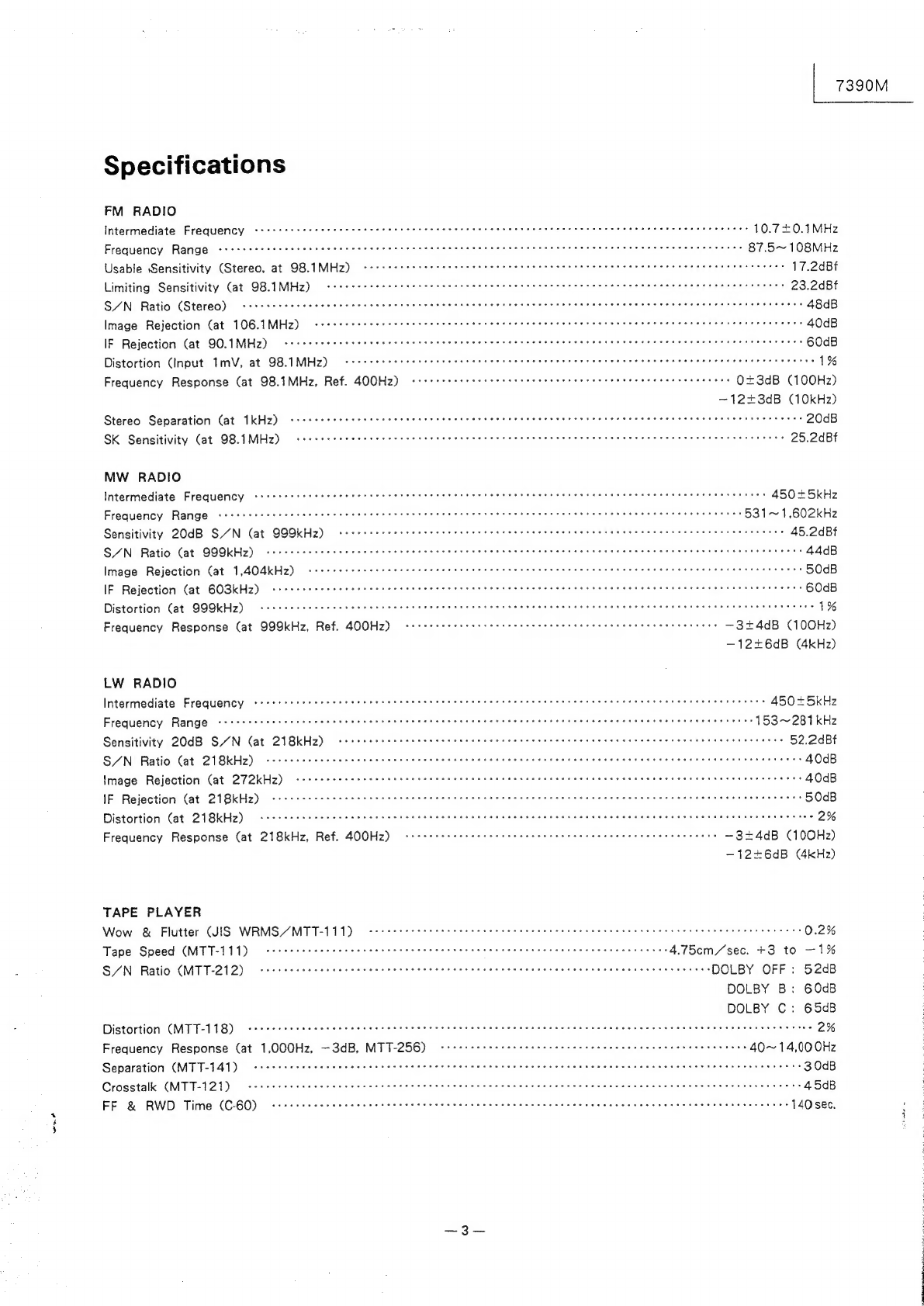
Alpine 7390M User manual

SERVICE
MANUAL
Z\LPIN
Digital
FM/MW/LW
Cassette
(With
built-in
CD
changer
controller)
@For
the
cassette
deck
mechanism
parts
(GR75E020)
of
this
model,
refer
to
the
GR
Series
Service
Manual
(Part
No.
68P20504W01).
FM
?
sx
ST
Ox
MTL
Disc
Tie
|
MUSIC
Pla
ae
maue
(13.2
OaP
SOK
Loud
SEEK
PAUSE
—
>
AMEMO
ONE
ALL
Mix
TUNER/CASSETTE
DECK
7390

7390M
|
a
Contents
ASTot=ketp
#1
0¢-
9 €
(0)
0
SiC
RRC
RC
3
to
4
LEFOAUCTION
cae
er
One
Rares
eee
Te
vad
ence
ose wee
SSs
we
ple
core
OR
cw
SE
Sree
wee
erary
og
ara
cide
oe
Goh
a
sea
4
FH
Ee
Ow
ene
gum
oats
Wale
asteatiere
bre
5
In
Case
of
Difficulty
--1esccte
secret
treet
eee
tree
nent
eee
eee
e
ene
t
eee
e
enter
ene
eee
enn
cnaee
Citys
Mester
oie
ea
5
to
8
Error
Indication
for
5952
cccceccrecrtceeeee
tees
ee
Oss
wate
ia
hse
el)
osteo
eiatasdeal
Sala
vealel
aletengts
wiese-e/e/Sisif.s'
acehed
o's
saderareann
nea
8
to
9
Features.
ee
cede
ddes
oot
Bak
eae
8
isis
Sees
sa
See
OE
ee
HEN
ee
SE
BD
a
a
Leese
SESE
A
bag
Lede
teenth
de
valor
Wee
Te
8
to
10
Controls
and
Indicators
srcese
reset
ee
eet
ene
nee
een
n
eee
Eee
EE
EEE
EEE
EEE
E
EEE
EE
EEE
EEE
EEE
eet
ES
10
to
11
[OFo)
alal=(ea
¢1 ©)
0
kaa
ee
ie
11
to
12
PreGaUtiOns:
enews
Renee
Me
Was
FA
Cae
wae
etre
nas
CS
ee
ata
aaa
CUe
a
Uineieies
ORIG
Sie
held
a
Vee
GaN
TS
UNE
anle
eS
kee
oe
ren
Canaan
Mine
13
(ofet
17-110):
ee
ee
eee
ee
eee
ee
eee
rere
14
to
18
Disassembly
Instructions
-<crcec
cere
tert
nen
eee
enn
eee
EEE
EEE
EEE
EEE
EE
EEE
EEE
eS
19
to
20
Adjustment
Procedures
cirrcrr
ttre
ect
e
een
ete
e
nner
e
tenet
ete
eee
n
eect
nen
e
eer
ene
eet
n
et
ete
tenses
21
to
22
Description
of
IC
Terminals
sceccrc
crc
r
errr
treet
eee
eee
teen
nee
eee
eee
en
eee
ETE
ene
EEE EEE
EEE
aes
23
to
27
Tuner
Schematic
Diagram
crrcrcctttr
rere
teeter
teen
eee
eter
eee
ener
eee
e
eee
e
ene
n
tnt
e
etter
aetna
n
ee
28
Block
Diagram
vrrrcc
eset
cette
teen
ee
ee
eee
ene
ne
eee
ene
E
eee
enna
eet
eet
een
Eee
ere
eee
nen
E
ES
29
Packing
Assembly
Parts
List
a
a
30
Packing
LV
Peh
aa
tete
MAYA
=
0)
30
Parts
Layout
on
P.
C.
Boards
and
Wiring
Diagram
(1/2)
cceccrr
secret
treet
e
eee
cence
ete
e
renee
een
eees
31
to
33
Parts
Layout
on
P.
C.
Boards
and
Wiring
Diagram
(2/2)
rrrrerreset
cette
etree
ete
e
nee
te
ee
ee
ee
een
cnn
cees
34
to
36
Schematic
Diagram
(1/3)
cecercree
eee
eee
ene
nnn
ener
EERE
EEE
EEE
Een
Ere
EE
37
to
39
Schematic
Diagram
(2/3)
crrcreree
rere
eee
et
EEE
EEE
EERE
E
EEE REE EEE EEE EEE
EEE
Eee
Ee
40
to
42
Schematic
Diagram
(3/3)
cccccceccc
cece
esse
teen
eee
e
rere
eee
eee
e
nee eee
EERE
EEE
Ee
EEE
Eee
ETRE
REE
E
EE
EEE
EEE
43
to
45
Electrical
Parts
List
ccccec
crc
t
etree
tr
ttre
eee
eee
ene
eee
ee
en
ene
nent
tne
etre
enter
eee
a
tent
neteeeeeaee
46
to
53
Exploded
View
(Cabinet)
a
54
to
55
Cabinet
Assembly
2)
oe
Ok)
cc
cca
56
Semi-Conductor
Lead
Identifications
<ceecccte
settee
eee
tte
tee
teen
eee
eee
eee
e
eee
eee
eee
ee
tenn
e
tesa
ne
etes
57
to
64
ae
Ee
SAT
RO
ae
eee
eng
SPRL
ee
eRe
ee

wn
7390M
Specifications
FM
RADIO
Intermediate
Frequency
Pr
a
cs
10.7+0.1MHz
Frequency
Range
a
i
a
ee
cc
is
87.5~108MHz
Usable
Sensitivity
(Stereo,
at
98.1MHz)
ee
er
a
17.2dBf
Limiting
Sensitivity
(at
98.1MHz)
eo
23.2dBt
S/N
Ratio
(Stereo)
rc
48dB
Image
Rejection
(at
106.1MHz)
ccerrcrcre
terete
etree
rte
t
etree
ete
tenn
tenet
teen
eect
teen
rete
nena
ener
s
een
es
tees
40dB
IF
Rejection
Cat
90.1MHz)
i
ee
cy
60dB
Distortion
(Input
TmvV,
at
98.1MHz)
i
1%
Frequency
Response
(at
98.1MHz,
Ref.
400Hz)
ee
ee
0+3dB
(100Hz)
—1223dB
(10kHz)
Stereo
Separation
(at
1kHz)
emer
ee me
ee me
eee
eee
eee
Ree
ERE
E
EO
REE
RESTO
EH
EEE
DERE
EEE
Eee
Ee
EEE
rere
eeeeeae
20dB
SK
Sensitivity
(at
98.1MHz)
i
ee
ee
ie
ce
25.2dBf
MW
RADIO
Intermediate
Frequency
ccrccc
crt
t
terse
ere
treet
ene
e
nett
cence
n
ete
eee
e
eens
t
nett
ene
e
nest
teense
esas
eee
aes
450+5kHz
Frequency
Range
aa
a
re
a
a
531~1,602kHz
Sensitivity
20dB
SAN
(at
999kHz)
Rem
em
meme
reece
name
eee
e
eH
eee
Eee
eee
eee
ees
see
ereeeserneersussosrisere
45.2dBt
S/N
Ratio
(at
999kHz)
rr
ee
rr
ry
44dB
Image
Rejection
(at
1,404kHz)
ee
a
a
50dB
IF
Rejection
Cat
603kHz)
i
i
i
cD
60dB
Distortion
(at
999kHz)
ee
ee
ci
1%
Frequency
Response
(at
999kHz,
Ref.
400Hz)
<srrereett
est
r
eter
eee
et
teen
eee
e
ett
eee
e
ees
—3+4dB
(100Hz)
—12+6dB
(4kHz)
LW
RADIO
Intermediate
Frequency
<srrrsrrrc
cere
terete
ttt
tenner
e
eee
eter
renee
een
e
ern
n
nner Ener
ne
es
450
+5kHz
Frequency
Range
<crrtrrsrrtt
tse
e
rete
eee
teen
nents
rennet
nee
e
ete
e
eee
eee
een
n
ene
n
etna
eect
tees
153~281kHz
Sensitivity
20dB
SYN
(at
218kHz)
ee
cic
52.2dBt
S/N
Ratio
(at
218kHz)
i
ie
ec
40dB
Image
Rejection
(at
272kHz)
ee
i)
40dB
IF
Rejection
(at
218kHz)
i
i
i
ec
cy
50dB
Distortion
(at
218kHz)
ers
2%
Frequency
Response
(at
218kHz,
Ref.
400Hz)
i
i
i
—324dB
(100Hz)
—12=+6dB
(4kHz)
TAPE
PLAYER
Wow
&
Flutter
(IS
WRMS/MTT-111)
ccoceteceectteretectererseeeneernteeseens
een
erne
scenes
etbees
eee
nen
ens
0.2%
Tape
Speed
(MTT-111)
crrceceec
cere
er
ee
eee
ete
e
ene
e
ene
eee
eee
eens
eee
ene
e
ete
ees
4.75cm/sec.
+3
to
—1%
S/N
Ratio
(MTT-212)
-crceeceeceerercee
eee
renneeeeeeenee
en
ensressneenseeenenaeeneseneeseeneees
DOLBY
OFF:
52dB
DOLBY
B:
60dB
DOLBY
C:
65dB
Distortion
(MTT-118)
crrcere
rete
eect
etree
rere
tent
eee
ete
e
cree
eee
e
eee
e
tenet
nee
e
ere
ee
ta
neeesesrerece
eet
ttes
2%
Frequency
Response
(at
1,000Hz,
—3dB,
MTT-256)
-verrree
rere
eect
etter
terete
eee
eee
eee
e
eee
e
ee es
40~14,000Hz
Separation
(MTT-141)
cceccect
eset
seen
eee
ener
eetetet
teen
tenn
nent
e
eee
e
eee
e
tenet
teen
n
eee
en
eaten
teet
nner
eee
aees
30dB
Crosstalk
(MTT-121)
cre
r
terete
enn
nent
eee
nee
nee
e
ener
ene
e
Ene
t
ete
e
ten
nee
Eee
teeta
nent
tS
45dB
FF
&
RWD
Time
(C60)
ccrcrr
reece
rete
ete
n
ene
nen
een
eee
e
een
eee
een
e
ee
nen
een
eee
eens
teense
140sec.
~3—-
i

7390M
GENERAL
Power
Supply
ccecs
creer
ete
eee
eee
een
nee
ene
e
nee
enn
eee
Ente
e
ere
n
ete
e
EEE
e
teen
eee
14V
DC
Pre-Out
Voltage
Impedance
ee
ee
eee
ee
er
eC
ee
ee
ee
ee
ee ee
eee
ee
ee
ee
eat
er
te
ee
ae
ar
eee
ed
0.56V/
10k
ohms
SEMICONdUCTOSS:
ss
ss
seeh
ste
ee
Ewes
Fas
tae
eee
eee
ened
gers
Bae
Sie
aes
23
IC's.
66
Transistors,
36
Diodes,
15
Zener
Diodes
DiniOHSiOhis:
oe
ssae
ie
OE
hate
ce
ch
aecie
cna
eee
was
wteincke
Heltaee
in
g
Minna
te
ages
Nosepiece:
171
(W)
x
50
(H)
xX
15
(D)
mm
Chassis:
178
(W)
x
50
(H)
x
143
(D)
mm
Waight:
sctssebsGe
econ
Stes
asteiaecncived
pred
Darth
es
cca
bie
aeaaiis
tually
staiakne
e
dole
e
ewassiou
daeecee
seen
suniss
2.4kg
NOTE:
Due
to
continuing
product
improvement,
specifications
and
designs
are
subject
to
change
without
notice.

INTRODUCTION
IN
CASE
OF
DIFFICULTY
IN
CASE
OF
DIFFICULTY.
The
Alpine
7390M
is
a
state-of-the-art
compact
disc
changer
controller,
cassette
deck,
and
FM/MW/LW
digital
PLL
synthesized
tuner
combined
in
one
DIN-size
unit.
It
incorporates
our
most
advanced
full
logic
tape
deck
(the
GR
mechanism)
and
built-in
controls
which
allow
direct
interface
with
Alpine’s
new
compact
disc
changer,
the
5952.
To
complete
the
package,
we
add
the
T-10
II
tuner
which
provides
ultra-wide
frequency
response,
excellent
signal-to-noise
characteristics,
and
exceptionally
stable
reception.
The
7390M
was
designed
for
in-dash
installation
in
vehicles
with
12-volt
negative
ground
electrical
systems.
Please
read
this
manual
thoroughly
to
familiarize
yourself
with
each
control
and
function.
We,
at
Alpine,
hope
you
receive
many
years
of
enjoyment
from
your
new
7390M.
-
if
you
encounter
a
problem,
please
review
the
items
in
the
following
checklist.
This
guide
will
help
you
isolate
the
probiem
if
it
is
really
the
head
unit
at
fault.
Otherwise,
make
sure
the
rest
of
your
system
is
properly
connected.
INITIAL
TURN-ON
No
Function
or
Display
Functions
OK
but
no
Sound
CD
not
functioning
Car's
ignition
is
off.
Power
Switch
off.
Improper
Connection
of
power
leads.
Blown
Fuse.
Volume
/evel
too
low.
Processors
or
Amplifiers
not
turning
on.
Out
of
operating
temperature
range
50°C
(120°F)
for
CD.
Moisture
condensation
in
the
CD
Module.
If
connected
per
instructions,
the
unit
will
not
operate
with
the
car's
ignition
off.
With
the
car’s
ignition
on,
turn
the
Volume
Control
clockwise
to
turn
power
on.
Check
connections
of
the
power
leads.
Check
the
fuses
on
the
Ignition
and
Battery
leads;
replace
with
the
proper
value
if
necessary.
Turn
Volume
Control
clockwise
to
desired
level.
Make
sure
Remote-on
Lead
is
connected
properly;
make
sure
processors
and
amplifiers
are
properly
wired.
Allow
the
temperature
of
the
car's
interior
(or
trunk)
to
cool.
Allow
the
enough
time
for
the
condensation
to
evaporate
(about
1
hour).
RADIO
MODE
Unable
to
receive
stations
Unable
to
tune
stations
in
the
Seek
mode
Broadcast
is
noisy
No
Antenna
or
open
connection
in
cable.
You
are
in
a
weak
signal
area.
If
the
area
you
are
in
is
not
known
to
be
a
weak
signal
area,
the
antenna
may
not
be
grounded
and
connected
properly.
The
antenna
may
not
be
the
proper
length.
The
antenna
is
not
the
proper
length.
The
antenna
is
poorly
grounded.
Make
sure
the
antenna
ts
properly
connected;
replac
antenna
or
cable
if
necess
Make
sure
the
tuner
is
in
DX
mode.
Check
your
antenna
connections;
make
sure
t!
antenna
is
properly
grou
its
mounting
location.
Make
sure
the
antenna
is
extended:
if
broken
replac
antenna
with
new
one.
Extend
the
antenna
fully;
replace
it
(f
it
is
broken.
Make
sure
the
antenna
is
grounded
properly
at
its
mounting
location.

|
IN
CASE
OF
DIFFICULTY
IN
CASE
OF
DIFFICULTY
|
IN
CASE
OF
DIFFICULTY
nter
a
problem,
please
review
the
items
in
the
following
checklist.
This
you
isolate
the
problem
if
it
is
really
the
head
unit
at
fault.
Otherwise,
rest
of
your
system
is
properly
connected.
ON
Car's
ignition
is
off.
Power
Switch
off.
Improper
Connection
of
power
leads.
Blown
Fuse.
If
connected
per
instructions,
the
unit
will
not
operate
with
the
car's
ignition
off.
With
the
car's
ignition
on,
turn
the
Volume
Control
clockwise
to
turn
power
on.
Check
connections
of
the
power
leads.
Check
the
fuses
on
the
Ignition
and
Battery
leads:
replace
with
the
proper
value
if
necessary.
Volume
level
too
low.
Processors
or
Amplifiers
not
turning
on.
Out
of
operating
temperature
range
50°C
(120°F)
for
CD.
Moisture
condensation
in
the
CD
Module.
“Tr
urn
Volume
Control
clockwise
to
desired
level.
Make
sure
Remote-on
Lead
is
connected
properly;
make
sure
processors
and
amplifiers
are
properly
wired.
Allow
the
temperature
of
the
car's
interior
{or
trunk)
to
cool.
Allow
the
enough
time
for
the
condensation
to
evaporate
(about
1
hour).
RADIO
MODE
Unable
to
receive
stations
Unable
to
tune
stations
in
the
Seek
mode
Broadcast
is
noisy
No
Antenna
or
open
connection
in
cable.
Make
sure
the
antenna
is
properly
connected;
replace
the
antenna
or
cable
if
necessary.
You
are
in
a
weak
signal
area.
\f
the
area
you
are
in
is
not
known
to
be
a
weak
signal
area,
the
antenna
may
not
be
grounded
and
connected
properly.
The
antenna
may
not
be
the
proper
length.
The
antenna
is
not
the
proper
length.
The
antenna
is
poorly
grounded.
Make
sure
the
tuner
is
in
the
DX
mode.
Check
your
antenna
connections;
make
sure
the
antenna
is
properly
grounded
at
'ts
mounting
location.
Make
sure
the
antenna
is
fully
extended;
if
broken
replace
the
antenna
with
new
one.
Extend
the
antenna
fully;
replace
it
if
it
is
broken.
Make
sure
the
antenna
is
grounded
properly
at
its
mounting
location.
TAPE
MODE
Cassette
insertion
not
possible
Unable
to
Fast-For-
ward
or
Rewind;
Fast-Forward
or
Rewind
is
very
slow.
Poor
High
Frequency
response
Excessive
tape
hiss
Tape
speed
fluctuates
There
is
a
cassette
already
in
the
transport.
The
cassette
is
being
improperly
inserted.
Eject
the
cassette
in
transport
and
remove.
Make
sure
the
cassette
is
being
inserted
per
instruction
in
The
cassette
has
been
damaged
or
the
tape
is
very
old.
Low
quality
recording
tape.
Tape
head
dirty.
Dolby
activated
for
a
non-Dolby
recorded
tape.
Tape
head
out
of
alignment.
Dolby
not
activated
for
Dolby
encoded
tape.
Dirty
Pinch-rollers/
Capstan;
Worn
motor
or
drive
belt.
Owner's
Manual.
Eject
the
cassette
and
discard:
using
a
damaged
or
very
old
cassette
in
your
unit
can
cause
damage
to
the
transport.
Compare
the
sound
with
a
cassette
using
high
quality
tape.
Clean
the
head
per
Owner's
Manual
instructions.
Make
sure
the
Dolby
functions
are
deactivated.
Return
to
Authorized
Center
for
service.
Make
sure
the
proper
Dolby
function
is
activated.
Return
to
Authorized
Center
for
service.

7390M
7390M
FEATURES
FULL
FRONT
DIN™
CHASSIS
7390M
|
IN
CASE
OF
DIFFICULTY
CD
CHANGER
MODE
ERROR
INDICATION
FOR
5952
No
CD
functions
Music
skips
excessively
Playback
of
3”
discs
does
not
work
DIN
Control
cable
not
connected.
The
CD
magazine
has
not
been
inserted.
The
5952
has
not
been
mounted
securely.
The
transit
Screws
were
not
removed
before
installation.
The
mounting
angle
of
the
5952
is
excessive.
The
CD
being
played
is
dirty.
The
CD
being
played
is
damaged.
The
3”
adaptor
ring
Is
not
being
used.
Make
sure
cables
for
control
and
audio
have
been
properly
connected
per
the
5952.
Install
the
magazine
with
at
least
one
CD
inserted.
Follow
the
installation
instructions
in
the
5952
manual
for
proper
installation.
Remove
the
Transit
Screws
and
reinstall
the
changer.
Remount
the
5952
according
to
the
directions
given
in
the
installation
manual.
Clean
the
CD
being
very
careful
not
to
scratch
it.
If
the
CD
in
question
is
cracked
or
warped,
discard
it
as
it
could
cause
damage
to
the
CD
mechanism;
if
the
CD
is
scratched
at
one
selection
only,
skip
that
selection
using
the
Music
Sensor
function
to
play
the
remaining
selections.
Place
the
3”
adaptor
ring
onto
the
disc
before
inserting
into
the
magazine.
CAUSE
Disc-change
malfunction.
Pa
be
1
3c
ome
ot
Disc
is
in
player
mechanism.
Disc-change
malfunction.
ee
Dea
Ded
ae
Disc-change
malfunction.
SOLUTION
Consult
your
Alpine
dealer.
Press
the
magazine
eject
button,
and
insert
an
empty
magazine.
If
the
code
disappears
within
a
few
seconds,
unit
is
O.K.
If
not,
consult
your
Alpine
dealer.
Press
the
magazine
eject
button
and
pull
out
the
Magazine.
And
check
no
error
indication.
Try
again.
If
the
magazine
can
not
be
pulled
out,
consult
your
Alpine
dealer.
Magazine
ejection
impossible.
Press
the
magazine
eject
button.
lf
the
magazine
does
not
eject,
consult
your
Alpine
dealer.
High
Temperature.
Misconnection
or
discon-
nection
of
CD
changer.
No
CD
magazine
in
the
CD
changer.
No
CD
at
No.
2
pocket
of
CD
magazine.
Will
disappear
when
the
temperature
returns
to
operation
range.
Check
connection
between
CD
changer
and
control
unit.
Insert
the
CD
magazine.
Insert
a
CD
into
the
No.
2
pocket
of
CD
magazine.
*
CD
CHANGER
CONTROLS
(When
used
with
the
Alpine
5952)
HLTAC™
TAPE
HEAD:
The
HLTAC
tape
head
provides
an
exceptionally
flat
frequency
respon
QUICK
RELEASE
BRACKET
(Q.R.B.):
Alpine's
exclusive
Q.R.B.
design
allows
for
easy
removal
of
the
7390N
maintaining
memory.
The
7390M
may
then
be
carried
with
the
owne:
prevention.
;
PRESET
ADDRESS:
The
indicators
on
the
Lite
Touch™
preset
buttons
will
light
when
you
|
lets
you
know
which
preset
station
is
on
(in
the
Radio
mode).
A.
MEMO
(AUTO
MEMORY):
In
the
Auto
Memory
mode,
the
6
strongest
FM,
MW
or
LW
stations
v
automatically.
D.A.P.
(DIRECT
ACCESS
PRESET):
D.A.P.
allows
the
storage
of
FM,
MW
and
LW
presets
on
the
same
b:
the
need
to
press
the
TUNER/BAND
button.
Up
to
6
FM
and
MW/LW
stations
can
be
mixed
in
the
D.A.P.
Band.
FULL
LOGIC
DECK
WITH
TRUE
FAST
FORWARD
AND
REWIND
IGNITION
“KEY
OFF”
PAUSE:
The
tape
head
and
pinch
roller
disengage
from
the
tape
when
the
igni
but
the
cassette
remains
inside
the
deck.
AUTO
METAL
:
When
a
metal
cassette
tape
is
inserted,
the
tape
mechanism
automat
metal
tape
equalization
(70
usec).
REPEAT
:
Permits
repeat
playing
of
a
musical
selection
on
the
tape.
In
the
CD
r
repeat
a
musical
track
or
an
entire
disc.
DUAL
PREAMP
OUTPUTS
:
The
7390M
allows
you
to
expand
your
system
easily
with
Front
and
R
and
PREAMP
Fader.
DOLBY*
B
NOISE
REDUCTION
DOLBY*
C
NOISE
REDUCTION
MUSIC
SENSOR
:
Allows
you
to
access
the
beginning
of
the
current
or
next
musical
sele
tape
using
Fast
Forward
and
Fast
Reverse.
AUTO
BLANK
SKIP
LITETOUCH™
30-STATION
PRESETS:
FM1:
6,
FM2:
6,
MW:
6,
LW:
6,
D.A.P.:
6
OPTIONAL
WIRELESS
REMOTE
CONTROL
(4390)
Noise
reduction
manufactured
under
license
from
Dolby
Laboratories
Corporation.
“Dolby”
and
the
double-D
symbol
are
trade
marks
of
Doi
Licensing
Corporation.

CAUSE
|
ERROR
INDICATION
FOR
5952
SOLUTION
Disc-change
malfunction.
ri
Lig
~
rt
ot
res
Disc
is
in
player
mechanism.
Disc-change
malfunction.
Disc-change
malfunction.
Magazine
ejection
impossible.
High
Temperature.
Misconnection
or
discon-
nection
of
CD
changer.
No
CD
magazine
in
the
CD
changer.
No
CD
at
No.
2
pocket
of
CD
magazine.
Consult
your
Alpine
dealer.
Press
the
magazine
eject
button,
and
insert
an
empty
magazine.
lf
the
code
disappears
within
a
few
seconds,
unit
is
O.K.
If
not,
consult
your
Alpine
dealer.
Press
the
magazine
eject
button
and
pull
out
the
Magazine.
And
check
no
error
indication.
Try
again.
If
the
magazine
can
not
be
pulled
out,
consult
your
Alpine
dealer.
Press
the
magazine
eject
button.
lf
the
magazine
does
not
eject,
consult
your
Alpine
dealer.
Will
disappear
when
the
temperature
returns
to
operation
range.
Check
connection
between
CD
changer
and
control
unit.
Insert
the
CD
magazine.
Insert
a
CD
into
the
No.
2
pocket
of
CD
magazine.
7390M
7390M
FULL
FRONT
DIN™
CHASSIS
CD
CHANGER
CONTROLS
(When
used
with
the
Alpine
5952)
HLTAC™
TAPE
HEAD:
The
HLTAC
tape
head
provides
an
exceptionally
flat
frequency
response.
QUICK
RELEASE
BRACKET
(Q.R.B.):
Alpine’s
exclusive
Q.R.B.
design
allows
for
easy
removal
of
the
7390M,
while
still
maintaining
memory.
The
7390M
may
then
be
carried
with
the
owner
for
theft
prevention.
;
@
PRESET
ADDRESS:
The
indicators
on
the
Lite
Touch™
preset
buttons
wil!
light
when
you
press
them.
This
lets
you
know
which
preset
station
is
on
(in
the
Radio
mode)
@
A.
MEMO
(AUTO
MEMORY):
In
the
Auto
Memory
mode,
the
6
strongest
FM,
MW
or
LW
stations
will
be
stored
automatically.
@
D.A.P.
(DIRECT
ACCESS
PRESET):
D.A.P.
allows
the
storage
of
FM,
MW
and
LW
presets
on
the
same
band,
eliminating
the
need
to
press
the
TUNER/BAND
button.
Up
to
6
FM
and
MW/LW
stations
can
be
mixed
in
the
D.A.P.
Band.
FULL
LOGIC
DECK
WITH
TRUE
FAST
FORWARD
AND
REWIND
IGNITION
“KEY
OFF”
PAUSE:
The
tape
head
and
pinch
roller
disengage
from
the
taoe
when
the
ignition
is
turned
off,
but
the
cassette
remains
inside
the
deck.
@
AUTO
METAL
:
When
a
metal
cassette
tape
is
inserted,
the
tape
mechanism
automatically
adjusts
to
metal
tape
equalization
(70usec).
@
REPEAT:
Permits
repeat
playing
of
a
musical
selection
on
the
tape.
In
the
CD
mode
you
may
repeat
a
musical
track
or
an
entire
disc.
@
DUAL
PREAMP
OUTPUTS
:
The
7390M
allows
you
to
expand
your
system
easily
with
Front
and
Rear
RCA
Outputs
and
PREAMP
Fader.
DOLBY*
B
NOISE
REDUCTION
DOLBY*
C
NOISE
REDUCTION
MUSIC
SENSOR
:
Allows
you
to
access
the
beginning
of
the
current
or
next
musical
selection
on
the
tape
using
Fast
Forward
and
Fast
Reverse.
AUTO
BLANK
SKIP
LITETOUCH™
30-STATION
PRESETS:
FM1:
6,
FM2:
6,
MW:
6,
LW:
6,
D.A.P.:
6
OPTIONAL
WIRELESS
REMOTE
CONTROL
(4390)
*
Noise
reduction
manufactured
under
license
from
Dolby
Laboratories
Licensing
Corporation.
“Dolby”
and
the
double-D
symbol
are
trade
marks
of
Dolby
Laboratories
Licensing
Corporation.
CONTROLS
AND
INDICATORS
O
@
OM
OOO®
1919
@0
@)
FM
2)
own
TIME
MUSIC
DA
SEEM
PAUSE
=
AMEMO
ONEALL
«=
MIX
34)
83)
27)
26)

}
CONNECTIONS
This
unit
is
designed
for
12-volt
DC
negative
ground
operation.
Check
to
be
sure
that
your
vehicle
has
this
type
of
system
before
connecting
the
power
cable.
Antenna
Receptacle
Front
Output
RCA
Connectors
(Labeled
LINE
OUT
FIRONT)
RED
is
Right
and
WHITE
is
Left.
Rear
Output
RCA
Connectors
(Labeled
LINE
OUT
REAR)
RED
is
Right
and
WHITE
is
Left.
Fuse
Holder
(3A)
Power
Supply
Connector
Connect
to
Power
Wiring
Harness.
DIN
Connector
Connect
this
to
5952
CD
changer
only
for
control.
Input
RCA
Connectors
(Labeled
LINE
IN):
RED
is
Right
and
WHITE
is
Left.
NOTE:
The
7390M
uses
female
RCA
type
connectors
that
are
designed
to
connect
to
another
unit
(source
unit,
signal
processor,
or
amplifier)
having
RCA
connectors.
You
may
need
an
adaptor
to
convert
the
other
unit
to
this
format.
If
so,
please
contact
your
authorized
Alpine
dealer
for
assistance.
Dimmer
Control
Lead
(WHITE/BLUE)
This
lead
is
for
connection
to
a
rheostat
such
as
the
dashboard
light
dimmer
in
your
vehicle.
Applying
(+)12V
to
this
lead
causes
the
maximum
dimming.
Varying
the
voltage
controls
the
brightness
of
the
display.
This
allows
you
to:dim
the
unit's
display
with
the
dashboard
lights.
@
Audio
Interrupt
In
Lead
(PINK/WHITE)
Applying
(+)12V
to
this
lead
mutes
the
audio
output.
This
works
well
when
connecting
the
7390M
with
a
Cellular
Phone
equipped
w'th
Audio
Interface
output.
Removing
(+)12V
from
this
lead
deactivates
the
muting
circuit.
@
Audio
Interrupt
Out
Lead
(PINK/WHITE)
Connect
to
Audio
Interrupt
In
Lead
of
a
CD
player,
etc.
@
Power
Antenna
Lead
(BLUE)
When
loaded
with
a
power
antenna,
connect
to
the
+B
terminal
of
the
power
antenna.
©
©©
©
89
S)
@
Ground
Lead
(BLACK)
Connect
this
lead
to
a
good
chassis
ground
on
the
vehicle.
Make
sure
the
connection
is
made
to
bare
metal
and
is
securely
fastened
using
a
sheet
metal
screw.
®
Option
@
RCA
Extension
Cable
@®
RCA
Input
of
Amplifier
@@
Front
Speakers
(Right/Left)
@
Rear
Speakers
(Right/Left)
@®
Power
Wiring
Harness
Connect
the
BLUE/WHITE,
RED,
and
YELLOW
leads.
@
Remote
Turn-On
Lead
(Labeled
REMOTE
ON):
(BLUE/WHITE)
Connect
this
lead
to
the
remote
turn-on
lead
of
your
amplifier
or
signal
processor.
@
Switched
Power
Lead
(Labeled
IGNITION):
(RED)
Connect
this
lead
to
an
open
terminal
on
the
vehicle’s
fuse
box
or
another
unused
power
source
which
provides
(+)12V
only
when
the
ignition
is
turned
on
or
in
the
accessory
position.
CAUTION:
You
must
be
very
careful
when
connecting
wires
to
the
vehicle's
electrical
system.
Be
sure
you
do
not
interface
leads
that
are
being
used
for
factory
components
in
the
vehicle
(like
an
on-board
computer).
When
making
connections
at
the
fuse
box,
make
sure
there
is
an
appropriate
value
fuse
on
the
circuit
you
plan
to
use.
Failure
to
do
so
may
result
in
damage
to
the
unit
and/or
the
vehicle.
@
Battery
Lead
(YELLOW)
Connect
this
lead
to
the
positive
(+)
post
of
the
vehicie’s
battery.
@
Extension
DIN
Connector
@
5952
(Sold
separately)
7390M
PRECAUTIONS
@
When
replacing
the
fuse(s),
the
replacement
must
be
of
the
same
amperage
as
shown
on
the
fuse
holder.
If
the
fuse(s)
blows
more
than
once,
carefully
check
all
electrical
connections
for
shorted
circuitry.
Also
have
you
vehicle’s
voltage
regulator
checked.
Do
not
attempt
to
repair
the
unit
yourself.
Return
it
to
your
Alpine
dealer
or
the
nearest
Alpine
Service
Station
for
servicing.
@
In
order
to
ensure
proper
performance,
be
sure
the
temperature
in
your
vehicle
is
between
the
range
of
14°F
(—10°C)
to
140°F
(60°C)
before
turning
your
player
on.
Good
air
circulation
is
essential
to
prevent
heat
build-up
in
the
unit
(especially
in
hot
weather).
C-120
type
cassette
tapes
are
not
recommended
for
use
in
automobile
tape
players.
Prevent
any
foreign
objects
from
entering
the
cassette
opening
as
the
precision
mechanism
and
tape
head
may
be
damaged.
To
protect
your
cassette
tapes,
store
them
in
a
cool
place
away
from
dust,
dirt,
and
strong
magnetic
sources
such
as
electric
motors,
speakers
and
TV
sets.
Check
and
make
sure
any
slack
in
the
tape
is
taken
up
before
inserting
the
tape
into
the
unit.
A
loose
tape
could
cause
damage
to
the
unit
and
the
tape
itself.
Tighten
the
cassette
by
inserting
a
pencil
or
a
similar
instrument
into
the
spindle
hole
and
turn
until
all
the
slack
has
been
taken
up.
@
CAUTION:
In
the
event
of
road
vibration
or
rapid
acceleration
or
vehicle
collision,
this
unit
may
become
dislodged
from
its
case
unless
the
handle
is
fully
down.
This
could
result
in
personal
injury
to
occupants
of
the
vehicle
or
physical
damage
to
the
unit.
Please
see
the
illustrations
below
for
further
information
on
how
to
properly
secure
the
handle.
NOTE:
This
unit
has
a
special
volume
control
on
the
left
side
of
the
unit
for
adjusting
the
voiume
level
for
SDK
reception
and
the
alarm
which
will
sound
when
there
is
no
SK
signal
in
the
SDK
mode.
Set
the
volume
control
@
to
the
minimum
level
position,
and
adjust
the
special
volume
control
on
the
left
side
of
the
unit
to
your
desired
level
with
a
screwdriver.
—~—13—

CONNECTIONS
Refer
to
Fig.
1
on
page
4.
BASS
Control
TREBle
Control
DX/REPEAT
Switch
SDK
Switch
TUNER/BAND
Switch
TUNE/DISP
Button
Slot
for
Cassette
M.S.
-
CD
UP/FF
Button
(
>p
)
Numeric
Display
DISC
tndicator
Band
Indicator
Elapsed
TIME
Indicator
DX
Indicator
SK
Indicator
STereo
Indicator
MTL
Indicator
MUSIC
Indicator
Reset
Button
LOUD
Indicator
Tape
Direction
Indicator
M.L.X.
Indicator
SDK
Indicator
ONE/ALL
Repeat
Indicator
PAUSE
Indicator
A.
MEMO
Indicator
SEEK
Indicator
D.A.P.
Indicator
M.S.
-
CD
DN/REW
Button
(W<)
D.A.P./M.LX./LOUD
Button
DISC
»/
OOOO
OOOHOO
HHH
O88
HHH
GOHHHHHBHOSOOHOOHOHOONO
and
Turn)
Control
FADER
Control
(FAD)
®
Sensor
Window
For
Remote
Control
(Optional
4390
Wireless
Remote
Control)
Preset
and
Direct
Disc
Access
No.
Preset
and
Direct
Disc
Access
No.
Preset
and
Direct
Disc
Access
No.
Preset
and
Direct
Disc
Access
No.
Preset
and
Direct
Disc
Access
No.
Preset
and
Direct
Disc
Access
No.
1/Dolby
B
Button
and
Indicator
2/Dolby
C
Button
and
Indicator
4/B.
SKIP
Button
and
Indicator
6
Button
and
Indicator
5/PROG
Button
and
I{ndicator
3/M.S.
Button
and
Indicator
TAPE
>»
/
Wt
(PLAY/PAUSE)
Button
tt
(PLAY/PAUSE)
Button
Power
Switch
(Turn)/EJECT
Button
(PUSH)/VOLume
(Turn)
and
BALance
(PULL
pps
CONNECTIONS
CONNECTIONS
|
This
unit
is
designed
for
12-volt
DC
negative
ground
operation.
Check
to
be
st
your
vehicle
has
this
type
of
system
before
connecting
the
power
cable.
Antenna
Receptacle
Front
Output
RCA
Connectors
(Labeled
LINE
OUT
FRONT)
RED
is
Right
and
WHITE
is
Left.
Rear
Output
RCA
Connectors
(Labeled
LINE
OUT
REAR)
RED
is
Right
and
WHITE
is
Left.
Fuse
Holder
(3A)
Power
Supply
Connector
Connect
to
Power
Wiring
Harness.
DIN
Connector
Connect
this
to
5952
CD
changer
only
for
control.
Input
RCA
Connectors
(Labeled
LINE
IN):
RED
is
Right
and
WHITE
is
Left.
NOTE:
The
7390M
uses
female
RCA
type
connectors
that
are
designed
to
con
another
unit
(source
unit,
signal
processor,
or
amplifier)
having
RCA
cor
You
may
need
an
adaptor
to
convert
the
other
unit
to
this
format.
If
so
contact
your
authorized
Alpine
dealer
for
assistance.
®
Dimmer
Control
Lead
(WHITE/BLUE)
This
lead
is
for
connection
to a
rheostat
such
as
the
dashboard
light
dimmer
|
vehicle.
Applying
(+)12V
to
this
lead
causes
the
maximum
dimming.
Varyinc
voltage
controls
the
brightness
of
the
display.
This
allows
you
to
dim
the
uni
with
the
dashboard
lights.
@
Audio
Interrupt
In
Lead
(PINK/WHITE)
Applying
(+)12V
to
this
lead
mutes
the
audio
output.
This
works
well
when
connecting
the
7390M
with
a
Cellular
Phone
equipped
with
Audio
Interface
o
Remeving
(+}12V
from
this
lead
deactivates
the
muting
circuit.
@
Audio
Interrupt
Out
Lead
(PINK/WHITE)
Connect
to
Audio
Interrupt
In
Lead
of
a
CD
player,
etc.
@
Power
Antenna
Lead
(BLUE)
Wher
loaded
with
a
power
antenna,
connect
to
the
+B
terminal
of
the
powe
antenna.
e
©
©®©
©
89
@
Ground
Lead
(BLACK)
Connect
this
lead
to
a
good
chassis
ground
on
the
vehicle.
Make
sure
the
cc
is
made
to
bare
metal
and
is
securely
fastened
using
a
sheet
metal
screw.
®
Option
@
RCA
Extension
Cable
@
RCA
Input
of
Amplifier
@
Front
Speakers
(Right/Left)
@
Rear
Speakers
(Right/Left)
@
Power
Wiring
Harness
Connect
the
BLUE/WHITE,
RED,
and
YELLOW
leads.
@
Remote
Turn-On
Lead
(Labeled
REMOTE
ON):
(BLUE/WHITE)
Connect
this
lead
to
the
remote
turn-on
lead
of
your
amplifier
or
signal
proce
@
Switched
Power
Lead
(Labeled
IGNITION):
(RED)
Connect
this
lead
to
an
open
terminal
on
the
vehicle’s
fuse
box
or
another
ur
power
source
which
provides
(+)12V
only
when
the
ignition
is
turned
on
or
ir
accessory
position.
CAUTION:
You
must
be
very
careful
when
connecting
wires
to
the
vehicle’s
ele
system.
Be
sure
you
do
not
interface
leads
that
are
being
used
for
components
in
the
vehicle
(like
an
on-board
computer).
When
makil
connections
at
the
fuse
box,
make
sure
there
is
an
appropriate
value
the
circuit
you
plan
to
use.
Failure
to
do
so
may
result
in
damage
tc
and/or
the
vehicle.
@)
Battery
Lead
(YELLOW)
Connect
this
lead
to
the
positive
(+)
post
of
the
vehicle's
battery.
@
Extension
DIN
Connector
@
5952
(Sold
separately)
Ps
iy
em

-7390M
|
OPERATION
@
BASIC
OPERATION
Power
Switch
and
Volume
Control
&
Rotating
the
Power
Switch
49
clockwise
turns
power
ON
and
continuously
increases
the
volume.
Rotating
the
control
counterclockwise
will
continuously
decrease
the
volume,
and
turn
the
Power
Off.
Note:
Keep
the
volume
control
turned
fully
counterclockwise
before
your
program
starts.
Adjust
the
volume
by
gradually
turning
the
contro!
clockwise
once
playback
begins.
Do
not
turn
the
control
clockwise
abruptly
as
the
excessive
power
could
damage
the
speakers.
Balance
Control
@
Pull
on
the
Volume
Control
@
and
rotate
to
balance
between
left
and
right
speakers.
Fader
Control
Rotate
the
Fader
Control
@
for
your
desired
front
to
rear
volume
balance.
Separate
Bass
and
Treble
Controls
(©,
@)
;
Slide
these
controls
to
the
right
to
increase,
and
to
the
left
to
decrease
the
level
of
Bass
or
Treble.
Loudness
Press
and
hold
the
LOUD
button
@0
for
more
than
two
seconds
to
activate
the
loudness
function.
Press
and
hold
the
LOUD
button
for
more
than
two
seconds
again
to
defeat
this
feature.
Mode
Switching
of
the
7390M
1.
Radio
Mode
Press
the
TUNER
Switch
©
to
put
the
unit
into
Radio
mode.
The
Band
indicator
@
(FM,
MW
or
LW)
will
appear
in
the
display.
2.
Cassette
Player
Mode
Press
the
TAPE
button
&
to
put
the
unit
into
the
cassette
player
mode.
3.
C.D.
Changer
Mode
Press
the
DISC
button
@
to
put
the
unit
into
the
CD
mode.
If
the
Alpine
5952
CD
Changer
has
not
been
connected,
“E
E E
E"
will
appear
in
the
display
@.
@
RADIO
OPERATION
Turn
the
power
on
and
set
the
unit
to
the
Radio
mode.
Band
Selector
Switch
Press
the
BAND
Switch
©
to
select
the
desired
tuning
band.
The
Band
Indicator
@
shows
your
selection.
Local/Distance
(DX)
Sensitivity
Switching
for
FM,
MW
and
LW
You
can
select
the
radio
SEEK
sensitivity
(local
or
distance
(DX))
by
pressing
the
DX
Switch
©.
In
the
distance
mode,
with
DX
indication
@,
the
radio
tunes
in
both
strong
and
weak
stations
(from
A
to
M
in
the
illustration).
In
the
Local
mode,
with
no
DX
indication
@,
the
radio
tunes
in
only
strong
stations
(C,
F,
H
and
L
in
the
illustration).
-
Signal
Strength
hal
dalt
Station
Frequencies
—14—
OPERATION
Automatic
FM
Stereo/Monaural
Switching
During
FM
stereo
reception,
the
“ST”
indicator
©
lights
up.
When
the
station
signal
becomes
weak,
the
unit
automatically
switches
to
the
monaural
mode
to
reduce
the
noise
and
the
“ST”
indicator
disappears.
Should
the
signal
become
strong
enough,
the
unit
automatically
changes
back
to
the
stereo
mode.
Manual
Tuning
1.
Press
the
TUNE
button
©
until
the
SEEK
63
and
A.
MEMO
42
indicators
disappear
in
the
display
©.
2.
To
select
the
tuning
band,
press
the
BAND
Switch
©.
The
band
indicator
@
shows
your
selection.
3.
To
tune
to
higher
frequencies,
press
the
M.S.
-
CD
button
on
the
top
(UP)
®.
4.
To
tune
to
lower
frequencies,
press
this
same
button
on
the
bottom
(DowN)
@9.
Auto
Seek
Tuning
1.
Press
the
TUNE
button
©
until
the
SEEK
indicator
@
appears
in
the
display.
2.
Select
the
tuning
band
with
the
BAND
Switch
©.
3.
Press
the
UP
pp
or
DOWN
4
@
button.
The
unit
automatically
tunes
to
the
next
higher
or
lower
frequency
and
locks
on
that
station.
Manual
Memory
Preset
Follow
the
instructions
below
to
program
stations
into
preset
memory.
1.
Select
the
tuning
band
(FM1,
FM2,
MW,
LW)
@
with
the
BAND
switch
©.
2.
Tune
in
your
desired
station
by
manual
or
Auto
Seek
tuning.
3.
Press
and
hold
any
Preset
Button
(@
—
@)
for
more
than
two
seconds.
The
tuned
frequency
in
the
Numeric
Display
©
will
begin
to
blink.
Press
that
button
a
second
time
while
the
indication
is
blinking
(within
five
seconds.)
4.
Your
selected
station
will
be
placed
into
that
preset
location
and
the
indicator
will
light.
Note:
|f
a
preset
memory
has
already
been
programmed
in
that
location,
it
will
be
cleared
and
the
new
station
will
replace
in
the
preset
memory.
Auto
Memory
Preset
1.
Press
the
TUNE
button
©
to
light
up
the
A-LMEMO
indicator
2.
2.
Select
the
desired
tuning
band
(FM1,
FM2,
MW
or
LW)
@
with
the
BAND
Switch
@®.
3.
Press
the
UP
®
or
DN
@
button.
The
tuner
will
automatically
seek
the
six
strongest
stations
in
each
band
and
memorize
them
in
order
of
the
signal
strength.
These
stations
are
automatically
placed
in
the
preset
memory
with
the
strongest
station
in
Preset
No.
1
and
the
6th
strongest
station
in
Preset
No.
6.
When
seeking
stations,
the
tuner
first
seeks
in
the
local
tuning
mode.
If
less
than
6
stations
are
memorized,
the
tuner
seeks
again
in
the
distance
(DX)
mode.
4.
After
finishing
Auto
Memory
Preset,
the
tuner
goes
to
the
station
placed
in
preset
memory
No.
1.
If
no
stations
are
memorized,
it
returns
to
the
original
station
you
were
listening
to
before
the
auto
memory
preset
procedure
began.
Preset
Tuning
After
the
preset
stations
have
been
memorized,
you
can
tune
in
your
desired
station
(within
the
band
displayed)
with
one
touch
of
a
button.
1.
Select
the
tuning
band
(FM1,
FM2,
MW
or
LW)
@
with
the
BAND
Switch
©.
2.
Press
any
one
of
the
Preset
buttons
{@
—
@)
and
the
indicator
in
that
button
will
light.
3.
The
frequency
of
the
station
placed
in
the
selected
preset
location
will
appear
in
the
display.
D.A.P.
(Direct
Access
Preset)
This
feature
allows
the
storage
of
FM,
MW
and
LW
presets
on
the
same
band.
Press
the
D.A.P.
button
@
to
light
up
the
D.A.P.
indicator
6.
To
program
stations
into
the
D.A.P.
band,
follow
steps
2
—
4
as
described
in
the
Manual
Memory
Preset
section
on
Page
15.
Accessing
the
D.A.P.
Presets
1.
Press
the
D.A.P.
button
@.
The
D.A-P.
indicator
&
will
illuminate
in
the
display.
2.
Press
one
of
preset
buttons
(@—
@)
and
the
indicator
in
that
button
will
light.
3.
The
frequency
of
the
station
placed
in
the
selected
D.A.P.
location
will
appear
in
the
display.
—15—
7330M
7390M
|
OPERATION
Traffic
Information
Receiving
This
model
is
equipped
with
traffic
information
receiving
apparatus
to
£
Germany
where
the
traffic
information
is
broadcast
in
FM.
The
following
this
unit
to
receive
traffic
information
broadcasting.
1.
Select
FM
position.
2.
Depress
the
SDK
switch
@
and
tune
to
a
station.
If
the
station
is
a
tr
station,
the
SK
indicator
@
will
glow
and
show
the
reception
of
a
brox
traffic
information
station.
NOTE:
SK
Indicator
When
SK
signal
is
received
irrespective
of
the
SDK
switch
position,
tt
will
illuminate.
3. In
the
SDK
mode,
stations
other
than
traffic
information
stations
are
r
out.
Therefore,
it
is
easy
to
select
a
traffic
information
station.
4.
As
the
signal
of
the
tuned
traffic
information
station
becomes
weak,
1
will
extinguish.
Then
after
the
lapse
of
25
seconds,
a
rhythmical
alar
urge
retuning
to
another
stronger
station.
If
the
reception
of
further
t
is
required,
tune
in
the
desired
traffic
information
station.
When
rece
will
stop
and
the
SK
indicator
illuminates.
Since
the
alarm
will
contint
from
any
other
traffic
stations
can
be
received,
release
SDK
switch
fc
normal
broadcasting.
5.
When
the
unit
is
playing
a
tape
or
a
CD
with
the
SDK
switch
pushed
traffic
information
station,
the
tape
or
CD
play
is
interrupted
and
char
if
the
pre-tuned
station
begins
a
traffic
information
message.
When
1
over,
the
unit
reverts
to
tape
or
CD
play
automatically.
6.
Even
if
the
VOLUME
control
is
set
to
the
minimum
position,
the
volur
information
will
be
automatically
adjusted
to
proper
level.
After
the
n
sound
volume
returns
to
the
previously
adjusted
level.
7.
If
traffic
information
reception
is
no
longer
necessary,
release
SDK
sv
radio
reception.
NOTE:
When
the
SDK
switch
is
pressed
and
there
is
no
SK
signal,
ALA
after
the
lapse
of
25
seconds.
Press
the
SDK
switch
again
to
s
@
TAPE
PLAYER
OPERATION
Turn
the
unit
on
and
press
the
TAPE
»
/
&
button
@
to
access
the
t
Dolby*
B/C
Noise
Reduction
Before
playing
a
cassette
tape,
check
to
see
if
it
is
encoded
with
Dolb:
reduction.
:
Press
the
Dolby
B
or
C
button
(@
or
@)
when
playing
a
Dolby
encodec
B
or
Dolby
C
indicator
in
the
button
will
illuminate
to
show
you
which
noi:
system
you
have
activated.
Cassette
Loading
and
Reloading
1.
Insert
a
prerecorded
cassette
tape
into
the
tape
slot
©
with
the
open
your
right.
2.
If
the
cassette
tape
is
not
completely
loaded
into
the
deck,
lightly
pre
into
the
slot.
Eject
Press
the
EJECT
button
9
to
eject
the
cassette
tape
from
the
tape
mé
Playback
1.
Insert
a
prerecorded
cassette
tape
with
open
side
facing
right.
The
pl
immediately.
2.
If
a
cassette
tape
is
already
loaded
in
the
unit,
press
the
Play
(
»
/
Il
start
playback.
3.
To
stop
tape
play,
press
the
EJECT
button
69
or
turn
the
power
off
w
switch
69.

7390M
—s*W7390M
|
:
OPERATION
OPERATION
OPERATION
:
FM
Stereo/Monaural
Switching
M
stereo
reception,
the
“ST”
indicator
@
lights
up.
@
Station
signal
becomes
weak,
the
unit
automatically
switches
to
the
monaural
duce
the
noise
and
the
“ST”
indicator
disappears.
Should
the
signal
become
igh,
the
unit
automatically
changes
back
to
the
stereo
mode.
ining
ve
TUNE
button
©
until
the
SEEK
@9
and
A.
MEMO
@
indicators
disappear
in
lay
©.
ct
the
tuning
band,
press
the
BAND
Switch
©.
The
band
indicator
@
shows
lection.
to
higher
frequencies,
press
the
M.S.
-
CD
button
on
the
top
(UP)
®.
to
lower
frequencies,
press
this
same
button
on
the
bottom
(DowN)
@.
Tuning
ye
TUNE
button
©
until
the
SEEK
indicator
®
appears
in
the
display.
he
tuning
band
with
the
BAND
Switch
©.
ye
UP
pr
@®or
DowN
K<
@
button.
The
unit
automatically
tunes
to
the
jher
or
lower
frequency
and
locks
on
that
station.
mmory
Preset
e
instructions
below
to
program
stations
into
preset
memory.
ye
tuning
band
(FM1,
FM2,
MW,
LW)
@
with
the
BAND
switch
©.
your
desired
station
by
manual
or
Auto
Seek
tuning.
1d
hold
any
Preset
Button
(@
—
@)
for
more
than
two
seconds.
The
tuned
sy
in
the
Numeric.
Display
®
will
begin
to
blink.
Press
that
button
a
second
ile
the
indication
is
blinking
(within
five
seconds.)
ected
station
will
be
placed
into
that
preset
location
and
the
indicator
will
light.
If
a
preset
memory
has
already
been
programmed
in
that
location,
it
will
be
cleared
and
the
new
station
will
replace
in
the
preset
memory.
ory
Preset
e
TUNE
button
©
to
light
up
the
A.MEMO
indicator
@.
ve
desired
tuning
band
(FM1,
FM2,
MW
or
LW)
@
with
the
BAND
Switch
©.
@
UP
®
or
DN®
button.
The
tuner
will
automatically
seek
the
six
strongest
in
each
band
and
memorize
them
in
order
of
the
signal
strength.
These
are
automatically
placed
in
the
preset
memory
with
the
strongest
station
in
{o.
1
and
the
6th
strongest
station
in
Preset
No.
6.
When
seeking
stations,
the
st
seeks
in
the
local
tuning
mode.
If
less
than
6
stations
are
memorized,
the
@ks
again
in
the
distance
(DX)
mode.
ishing
Auto
Memory
Preset,
the
tuner
goes
to
the
station
placed
in
preset
No.
1.
If
no
stations
are
memorized,
it
returns
to
the
original
station
you
were
to
before
the
auto
memory
preset
procedure
began.
ing
preset
Stations
have
been
memorized,
you
can
tune
in
your
desired
station
vand
displayed}
with
one
touch
of
a
button.
xe
tuning
band
(FM1,
FM2,
MW
or
LW)
@
with
the
BAND
Switch
©.
ry
one
of
the
Preset
buttons
(@
—
@)
and
the
indicator
in
that
button
will
light.
uency
of
the
station
placed
in
the
selected
preset
location
will
appear
in
the
et
Access
Preset)
ire
allows
the
storage
of
FM,
MW
and
LW
presets
on
the
same
band.
Press
utton
@
to
light
up
the
D.A.P.
indicator
@.
To
program
stations
into
the
D.A-P.
steps
2
—
4
as
described
in
the
Manual
Memory
Preset
section
on
Page
15.
the
D.A.P.
Presets
2
D.A.P.
button
®.
The
D.A-P.
indicator
@
will
illuminate
in
the
display.
-@
of
preset
buttons
(@—
@)
and
the
indicator
in
that
button
will
light.
uency
Of
the
station
placed
in
the
selected
D.A.P.
location
will
appear
in
the
—15—
Traffic
Information
Receiving
This
model
is
equipped
with
traffic
information
receiving
apparatus
to
be
used
in
West
Germany
where
the
traffic
information
is
broadcast
in
FM.
The
following
is
how
to
use
this
unit
to
receive
traffic
information
broadcasting.
1.
Select
FM
position.
2.
Depress
the
SDK
switch
@
and
tune
to
a
station.
If
the
station
is
a
traffic
information
Station,
the
SK
indicator
@
will
glow
and
show
the
reception
of
a
broadcast
from
a
traffic
information
station.
NOTE:
SK
indicator
When
SK
signal
is
received
irrespective
of
the
SDK
switch
position,
the
SK
indicator
will
illuminate.
3.
In
the
SDK
mode,
stations
other
than
traffic
information
stations
are
muted
and
cut
out.
Therefore,
it
is
easy
to
select
a
traffic
information
station.
4.
As
the
signal
of
the
tuned
traffic
information
station
becomes
weak,
the
SK
indicator
will
extinguish.
Then
after
the
lapse
of
25
seconds,
a
rhythmical
alarm
will
sound
to
urge
retuning
to
another
stronger
station.
If
the
reception
of
further
traffic
information
is
required,
tune
in
the
desired
traffic
information
station.
When
received,
the
alarm
will
stop
and
the
SK
indicator
illuminates.
Since
the
alarm
will
continue
if
no
signals
from
any
other
traffic
stations
can
be
received,
release
SDK
switch
for
reception
of
normal
broadcasting.
5.
When
the
unit
is
playing
a
tape
or
a
CD
with
the
SDK
switch
pushed
in
and
tuned
to
a
traffic
information
station,
the
tape
or
CD
play
is
interrupted
and
changed
to
FM
radio
if
the
pre-tuned
station
begins
a
traffic
information
message.
When
the
message
is
over,
the
unit
reverts
to
tape
or
CD
play
automatically.
6.
Even
if
the
VOLUME
control
is
set
to
the
minimum
pasition,
the
volume
of
the
traffic
information
will
be
automatically
adjusted
to
proper
level.
After
the
message,
the
sound
volume
returns
to
the
previously
adjusted
level.
7.
If
traffic
information
reception
is
no
longer
necessary,
release
SDK
switch
for
normal
radio
reception.
NOTE:
When
the
SDK
switch
is
pressed
and
there
is
nc
SK
signal,
ALARM
will
sound
after
the
lapse
of
25
seconds.
Press
the
SDK
switch
again
to
stop
it.
@
TAPE
PLAYER
OPERATION
Turn
the
unit
on
and
press
the
TAPE
»
/
If
button
@
to
access
the
tape
mode.
Dolby*
B/C
Noise
Reduction
Before
playing
a
cassette
tape,
check
to
see
if
it
is
encoded
with
Dolby
B
or
C
noise
reduction.
Press
the
Dolby
B
or
C
button
(@
or
@)
when
playing
a
Dolby
encoded
tape.
The
Dolby
B
or
Dolby
C
indicator
in
the
button
will
illuminate
to
show
you
which
noise
reduction
system
you
have
activated.
Cassette
Loading
and
Reloading
1.
Insert
a
prerecorded
cassette
tape
into
the
tape
slot
@.with
the
open
side
facing
to
your
right.
2.
If
the
cassette
tape
is
not
completely
loaded
into
the
deck,
lightly
press
the
cassette
into
the
slot.
Eject
Press
the
EJECT
button
@
to
eject
the
cassette
tape
from
the
tape
mechanism.
Playback
1.
Insert
a
prerecorded
cassette
tape
with
open
side
facing
right.
The
playback
begins
immediately.
2.
If
a
cassette
tape
is
already
loaded
in
the
unit,
press
the
Play(
»/
)
button
@
to
start
playback.
3.
To
stop tape
play,
press
the
EJECT
button
@
or
turn
the
power
off
with
the
POWER
switch
9.
Pause
To
temporarily
stop
playback,
press
the
Pause
button
8.
To
resume
playback,
press
the
same
button
again.
Metal
(MTL)
Indicator
Metal
or
CrO,
cassette
tapes
having
an
open
detection
hole
will
automatically
be
detected,
in
which
case
the
MTL
indicator
@
in
the
display
comes
on
and
the
playback
equalization
is
automatically
set
to
70usec.
True
Fast
Forward
and
Rewind
1.
Press
the
FF
button
®
to
advance
the
tape
quickly.
Press
the
REW
button
®
to
rapidly
run
the
tape
backward.
The
deck
will
perform
these
functions
correctly
regardless
of
the
tape
play
direction.
2.
To
disengage
the
FF
or
REW
functions,
press
the
TAPE
(
»
/
Mf
}
button
@,
Music
Sensor
1.
Press
the
Music
Sensor
(M.S.)
button
@
and
its
indicator
will
light
up.
2.
Push
the
FF
button
®
to
advance
to
the
beginning
of
the
next
musica!
track.
Press
the
REW
button
@
to
go
back
to
the
beginning
of
the
current
musical
track.
3.
The
tape
deck
searches
forward
(or
back)
until
it
senses
a
blank
section
on
the
tape
and
begins
playback
at
that
point.
NOTE:
The
music
sensor
cannot
detect
blank
sections
of
less
than
three
seconds.
Auto
Reverse
When
the
tape
is
played
or
fast-forwarded
to
the
end,
the
tape
transport
automatically
reverses
the
tape
direction
and
playback
begins.
Manual
Reverse
To
manually
change
playback
direction
(switch
between
side
A
and
side
B),
press
the
PROG
button
@.
Repeat
1.
Insert
the
cassette
tape
and
begin
playback.
2.
When
you
find
a
selection
you
would
like
to
repeat,
press
the
REPEAT
switch
®
until
the
“ONE”
indicator
@appears
in
the
display.
This
selection
will
be
continuously
repeated
until
the
REPEAT
function
is
disengaged.
3.
To
cancel
the
repeat
function,
press
the
REPEAT
switch
®
again.
The
"ONE"
indicator
will
disappear.
Blank
Skip
1.
Press
the
B.
SKIP
button
@
during
playback
to
skip
over
any
blank
sections
of
tape
lasting
15
seconds
or
more.
2.
To
cancel
the
Blank
Skip
function,
press
the
B.
SKIP
button
@
again.
Head
Cleaning
When
playback
sound
quality
begins
to
deteriorate,
it
is
time
to
clean
the
tape
head.
insert
a
special
head
cleaning
cassette
into
the
tape
deck
and
allow
it
to
run
for
;
approximately
1
minute
to
remove
any
foreign
matter.
There
are
special
cleaning
cassettes
that also
clean
the
capstans
and
pinch
rollers.
Please
contact
your
authorized
Alpine
dealer
for
information
about
these
cleaning
devices.
—
16—

OPERATION
@
CD
OPERATION
The
following
instructions
apply
only
to
systems
that
incorporate
the
Alpine
5952
CD
changer
with
the
7390M.
Turn
the
unit
on
and
access
the
CD
mode
by
pressing
the
DISC
Play
button
@.
Initial
System
Turn-On
When
operating
the
system
for
the
first
time
after
installation
or
after
the
vehicle's
battery
has
been
disconnected
and
reconnected,
press
the
Reset
button
@
with
a
ball-point
pen
or
other
pointed
object.
CD
Display
Switching
In
the
CD
mode,
the
display
will
show
the
Disc
and
Track
Number
(Fig.
A)
or
the
Elapsed
Time
(Fig.
B).
Press
the
DISP
button
©
to
select
between
the
Disc/Track
number
and
the
Elapsed
Time
Indicators.
Fig.
B
Page,
Play
(Repeat
All)
Press
the
DISC
(
»
/
&
)
button
@.
:
The
Display
@
will
show
“
0-00
”
for
a
second,
then
“
1-01
“
will
be
displayed
and
the
first
track
on
the
first
disc
will
begin
playback.
3.
After
the
last
track
on
the
last
disc
is
played
back,
the
pickup
will
return
to
the
beginning
of
the
first
track
of
the
first
disc
and
begin
playback
from
that
point.
Pause
While
the
disc
is
playing,
press
the
DISC
(
>»
/
if
)
button
@
to
temporarily
stop
playback.
To
resume
playback,
press
the
DISC
button
@
again.
Music
Sensor
(Skip)
With
this
feature,
you
can
get
to
the
beginning
of
the
music
track
of
your
choice
simply
and
quickly.
It
is
functional
in
the
play
or
pause
mode.
The
display
@
shows
the
pickup
location
with
the
Track
Number.
To
advance
to
the
next
track
on
the
disc,
press
the
M.S.
-
CD
UP
button
©.
1.
Playback
stops,
the
pickup
moves
up
to
the
beginning
of
the
next
track.
The
display
@
shows
the
number
of
the
next
track.
2.
Playback
begins
immediately.
3.
If
you
wish
to
select
a
track
further
ahead
on the
disc,
continue
pressing
the
M.
S.°
cD
UP
button
®
until
you
reach
the
track
of
your
choice.
ee
OPERATION
|
To
replay
the
track
that
is
currently
playing,
press
the
M.S.
-
CD DN
button
®.
1.
Playback
stops,
the
pickup
moves
back
to
the
beginning
of
the
current
track.
The
track
number
display
will
remain
the
same.
2.
Playback
begins
immediately
from
the
beginning
of
the
track.
3.
If
you
wish
to
select
a
track
further
behind
on
the
disc,
continue
pressing
the
M.S.
+
CD DN
button
&
until
you
reach
the
track
of
your
choice.
Direct
Disc
Access
1.
Press
one
of
the
Direct
Disc
Access
buttons
(@
—
@)
to
select
from
discs
1
—
6.
The
disc
and
track
numbers
will
appear
in
the
display.
2.
Press
the
M.S.
+
CD
UP
©
or
DN
@
button
for
musical
track
selection.
Fast
Forward/Fast
Reverse
The
Fast
Forward/Fast
Reverse
feature
works
in
both
play
and
pause
modes.
1.
To
rapidly
move
the
pickup
forward,
press
the
M.S.
-
CD
UP
(
>»)
button
®
and
hold
it
down
for
more
than
one
second.
2.
To
rapidly
move
the
pickup
backward,
press
the
M.S.
-
CD
DN
(
4
)
button
8
and
hold
it
down
for
more
than
one
second.
3.
Continue
holding
the
UP
(»»1)
®
or
DN
(
#4)
@
buttons
until
you
reach
the
point
where
you
want
to
resume
playback.
4.
When
the
pickup
reaches
the
end
of
the
disc,
the
unit
will
go
into
the
Pause
mode.
REPEAT
(One/All)
This
feature
allows
you
to
continuously
repeat
a
single
track
or
one
entire
disc.
Ha
Repeat
a
Single
Track
Locate
the
music
track
of
your
choice
using
the
M.S.
-
CD
UP
®
or
DN
@
buttons.
2
Press
the
REPEAT
Switch
©.
The
repeat
indicator
“ONE”
@
will
illuminate.
The
music
track
will
be
played
back
repeatedly.
3.
To
stop
repeat
play,
press
the
Repeat
switch
twice.
The
indicator
switches
from
“ONE”
to
“ALL”
and
the
illumination
will
be
off.
To
Repeat
an
Entire
Disc
1.
While
playing
a
disc,
press
the
REPEAT
switch
©
until
the
“ALL”
indicator
@
is
displayed.
2.
The
disc
will
be
played
back
repeatedly.
3.
To
stop
repeat
play,
press
the
Repeat
switch
once.
The
indicator
illumination
will
be
off.
M.LX.
(Random
Play)
Press
the
M.I.X.
button
3
while
the
unit
is
in
the
play
or
pause
modes.
Musical
tracks
will
be
played
back
in
a
random
sequence
generated
by
the
micro
processor.
After
all
the
tracks
on
the
disc
have
been
played
back
once,
the
player
will
begin
a
new
random
sequence.

Disassembly
Instructions
1.
Removal
of
Nosepiece
(1)
After
removal
of
the
bracket
handle
and
top
cover,
remove
two
control
knobs
(VOLUME,
FADER)
as
shown
in
Figure
1.
(2)
Remove
five
hooks
marked
“O”
as
shown
in
Figures
1
and
2.
Nosepiece
Bottom
Cover
Figure
2
2.
Removal
of
Deck
Mechanism
(1)
After
removal
of
the
nosepiece,
remove
four
screws
marked
“xX”
as
shown
in
Figure
3.
(2)
Disconnect
a
connector
from
the
Main
P.
C.
Board.
7390M
Deck
Mechanism
SSS
Nosepiece
Bottom
Cover
Control
Knobs
(VOLUME,
FADER)
Figure
1
Deck
Mechanism
Main
P.
C.
Board
—19—
Front
P.
C.
Board
Figure
3
7390M
3.
Removal
of
Bottom
Cover
(1)
After
removal
of
the
Deck
Mechanism
and
Front
P.
C.
Board,
disconnect
all
connectors
from
the
QRB
connector.
(2)
Remove
the
solder
(A)
as
shown
in
Figure
4.
(3)
Remove
four
screws
marked
“A”
as
shown
in
Figure
4.
(4)
Bottom
cover
with
the
rear
chassis
and
QRB
connector
can
be
removed
completely.
Solder
(A)
QRB
Connector
4.
Removal
of
Main
P.
C.
Board
(1)
After
removal
of
the
bottom
chassis,
remove
the
nut
&
washer
as
shown
in
Figure
5.
(2)
Remove
the
solder
(B)
as
shown
in
Figure
5.
(3)
Remove
four
hooks
marked
“C]”
as
shown
in
Figure
5,
(4)
Disconnect
a
connector
from
the
remote-control
(E1).
Solder
(B)
Remote-control
(E1)
—
20
—
Rear
Chassis
Main
P.
C.
Board
Main
P.
C.
Board
Front
Chassis
Bottom
Front
P.
C.
Board
Cover
Nut
Figure
4
Solder
(B)
&
Washer
Figure
5

7390M
Adjustment
Procedures
1.
Tape
Player
(1)
Connection
T.P.1
(T.P.2)
[o-9])
=>
Test
Tape
Figure
6
P
(2)
Control
Setting
st
Power
Switch
PTTRRET
REL
Ce
ee
ee
ee
ee
ee ON
Fader
Control
s-rrrsrrrrstrctesereeee
Front
Position
Balance
Control
-+++++srrrret
eee
Mechanical
Center
Treble
“Bass
Control
-«s-+++++es:
Mechanical
Center
Other
Switch
«ccccce
crete
eer
ee
eee
ee
reece
scence
OFF
(3)
Adjustment
Procedures
T.P.1
(L)
Head
Azimuth
Adjust
for
Max.
and
same
Head
Azimuth}
MTT-114NB
;
:
Adj
14kH
Figure
6
TP2
(R
Adjustment
Screw
level
output
at
Normal
and
justment
(
2)
P.2
(R)
(Figure
7)
Reverse
Positions.
Dolby
Level
|
MTT-150
rice
@
|
TP!
(|
VAIOT
T.P.1
(L),
T.P.2
(R)
output
Adjustment
|
(400Hz)
e
T.P.2
(R)
|
VR102
(R)
for
245mV+14B.
Tape
Speed
|
MTT-111
T.P.1
(L)
|
Tape
Speed
T.P.1
(T.P.2)
for
2,970~
if
Figure
6
or
Adjustment
Adjustment
(3kHz)
T.P.2
(R)
(Figure
8)
3,090Hz.
Tape
Speed
Adjustment
Playback
Head
Head
Azimuth
Adjustment
Screw
=
ar
Motor
GR
Audio
P.
C.
Board
i
Figure
8
Figure
7
Pane)
ee

7380M
3
a
&
Main
P.
C.
Board
aay
yee

wee
HL
RB]
Wi
wd)
wl] wl]
a!
@d)
Oj
@d]
Wi
WIN
NMLNMI
NM]
M)]
hy
|
7390M
Description
of
IC
Terminals
@CXA10980
:
|C201
PB
FB
Playback
Feedback
IN,
OFF
/B/C
|__|
Dolby
NR
off/Btype/C-type
switching.
BIN
|
1
|
Playback
IN.
AL
IN
Calibration
IN,
No.
1
Under
primary
power
supply
operation
:
Ground,
Under
Secondary
power
supply
operation
:
Negative
power
supply.
Positive
power
supply
EC
IN
Ai<;
<
| ALO
|
Q}
&F
QO;
&
i
CAL/REC/PB
|
|
Calibration
/Resording
Payback
swing
SS
N,
Playback
Feedback
IN,
EC
FB
Recording
Feedback
IN.
=
foufoujfoufu
&
|WIN]
H-],oO
“N
ol,
BR]
@)
NM
—
ol
LLS
detector
time
constant
2.
Yo
connection
ND
Under
primary
power
supply
operation
:
VCC/2,
Under
secondary
power
supply
operation
:
Ground,
PF
H
CH
2
CH
1
VT
H
CL
2
®
alsialz|2l2z|[<|e2
o
|als
S|G
ww
Wy
to
NIN
IMI
M)aA]olo
WIN]
—-]|]O}]@oO};a;IN
a/4|s
tt
VT
L
PF
L
NT
S$
EC
OUT
EC
OUT
NT
S
PF
L
VT
L
LLS
weighting
N
LLS
detector
time
constant
1.
i
LLS
High-pass
filter.
>
Anti-saturation
LLS
weighting.
LLS
detector
time
constant
1
HLS
detector
time
constant
2,
99
Recording
OUT
(Encoded).
.
Recording
OUT
(Encoded).
CL
2
CH
2
PF
H
zlalal<|a]z}sla
aI
als
ala
3/2
=
o
on
mee
_

7390M
|
pa
[Re
«dN
eons
——SCSC~“*“‘S™SCCOCOC“‘“‘™SNNSCNNNNN
ras
[xc
|__|
No
connection
~——SS=CSCSCSCSC~“C“‘“‘“‘“‘(
Pas
[vr
in|
1
|
encoder
SSCS
LINE
OUT
|
©
|
Line
OUT
(Recoded),
47
|
GND
Under
primary
power
supply
operation
:
VCC/2.
Under
secondary
power
supply
operation
:
Ground.
REC
FB
Recording
Feedback
IN,
@LC7582
:
1C410
jx.
|
svmbt
|
vo
f
Temi
destin
ftom
aessnten
|
peaiaual
i
$1~S23
ns
Segment
OUT.
ae
$24~S43
—_
|
Segment
OUT.
[as
[Su
SPO)
|
170
|
Segment
OUT
DSP
INS
Segment
OUT/AD
IN.
es
Segment
OUT,/DSP
OUT.
S49
(ADO1)
S50
(AD02)
S51
(ADO3)
Segment
OUT/AD
OUT,
S52
(AD04)
S53
(AD05)
ss
[os
Oscillator,
Power
supply.
57
|
INH
Display
eighting
off
IN,
(Effective
to
output
driver.
So
serial
data
transfer
is
possible
while
eighting
is
off.)
og
ee
P60
CRS
ae
b=
|
Serial
data
transfer
IN,
En
Co
ee
(ee
Serial
data
transfer
IN,
|
62
{pata
|
ot
Serial
data
transfer
IN,
|
63
|comz
|
_o
|
Common
OUT
(COMI
is
used
when
1//1
duty).
|
64
{com
|
oT
Common
OUT
(COMI
is
used
when
1//1
duty).
—
24
—~

|
7390M
PLL
error
output
terminal,
|
oO
|
|
|
|
Device
power
supply
terminal.
@
94468F04
:
IC501
I
a
Input
terminal
for
local
oscillation
output
(VCO
output)
from
10
to
200MHz.
Device
selector
signal
input
terminal.
Device
power
supply
terminal.
Forced
monaural
selector
output
terminal.
MW/LW
IF
signal
input
terminal,
FM
IF
signal
input
terminal.
MW/LW
IF
FM
IF
SI
(CMD)
Command
data
input
terminal,
Sychronizing
clock
output
terminal
for
status
signal
reception.
Status
signal
output
terminal.
Communication
start
signal
output
terminal.
Mute
signal
output
terminal.
Local
mode
selector
output
terminal.
Crystal
oscillator
connection
terminal,
Ground
terminal
for
device,
No
connection
terminal.
Ground
terminal
for
device,
DK
signal
input
terminal
(MO).
SK
signal
input
terminal
(MO).
ST
signal
input
terminal.
Station
detector
input
terminal,
P47
{sm
{|
ot
Input
level
detector
input
terminal.
reel:
a
With/without
clock
selector
terminal.
295

7390M
|
@15590W07,
15522W04
:
IC601
=
1
RUN-DET
Take-up
reel
detector
input
terminal
for
GR
mechanism.
|
3
[PLaysor
|
o
|
Head
base
forward/back-ward
selector
output
terminal
for
GR
mechanism,
|
4[rrsor
|
o
|
Play
“fast-forward
(rewind)
selector
output
terminal
for
GR
Mechanism.
Ps
[eIECTSOL
|
0
|
est
solenoid
acwating
output
for
GR
mechaniem
———SSSSCS~S~*Y
PuOTORCT
|
oO
|
Motor
running
direction
selector
ouput
terminal
for
GR
mechani
=|
Por
[reser
|
1
[Reset
signal
input
termina
Cd
ae
a
Crystal/Ceramic
connection
terminal
for
system
clock
oscillation,
X2
in
case
of
external
clock,
input
to
X1
and
input
opposite
phase
to
X2,
|
10
[LEVELOF
|
oO
|
Music
sensor
gain
selector
output
terminal.
P11
|
MOTORFAST
|
0
|
Motor
rotons!
number
selector
output
terminal
for
GR
mechanim
[12
TomoToR
|
0
_|
Motor
rotaion//sop
selector
output
terminal
for
GR
mechanism
=
Pig
ER
te
On|
Audio
signal
FWD/REV
selector
output
terminal
for
GR
mechanism.
14
Pack
insertion
detector
input
terminal
for
GR
mechanism,
15
Metal
tape
detector
input
terminal.
Tape
non-recorded
portion
detector
input
terminal.
Preset
indicator
LED
lighting
selector
terminal.
18
[LEDON
20
[pTsce__|
zi
[soKez
|
zz
|
CHANGER
_|
z=
[poe
|
24
[oo
25
[KEYES
26
Loudness
selection
output
terminal.
s
lal
=
Cc
4
is)
=
—
NO
DTS
chip
enable
signal
output
terminal.
SDK
buzzer
signal
output
terminal.
5952/7390
audio
signal
selector
output
terminal.
Dolby-C
selector
output
terminal.
Dolby-B
selector
output
terminal,
Key
path
serial
data
selector
output
terminal.
Ground
(GND)
potential
terminal.
Ny
~“
<
n n
Accessory
power
detector
input
terminal,
9
|
DISPLY-DT
I
REMO-CON
I
31
BAND2
32
3
5952
display
data
input
terminal,
Remote
control
data
input
terminal.
to)
©
Destination
selector
input
terminal,
w
>
Z
=
>
Qa
a
With/without
SDK
selector
input
terminal.
@
n
1o)
al
With/without
auto
memory
selector
input
teminal.
(But
for
this
model,
connect
to
GND)
AUTO-ME
AUTO-ME
With/without
auto
memory
selector
input
teminal,
(But
for
this
model,
connect
to
GND)
With/without
auto
memory
selector
input
teminal,
(But
for
this
mode!,
connect
to
GND)
AUTO-ME
VOL-PUSHKEY
KEY-IN
Key
data
input
terminal,
MUTE
ae
DTS
mute
signal
input
terminal.
STRT
mae
DTS
communication
start
signal
input
teminal,
at
Sts.
eT
DTS
status
signal
input
terminal,
CMD
|
oO
|
DTS
command
data
output
terminal.
43.
}SCK
|
DTS
synchronous
clock
signal
input
terminal,
BATT
|
1
|
Battery
power
detector
input
terminal,
Eject
key
input
terminal.
W/WIi®
W
W
ODINIO
oO
ff
—
26
—
Other Alpine Cassette Player manuals