CONTENTS/INHALT/TABLE
DE
MATIERES/SOMMARIO/INDICE
Oo
Fig
WAbbe
1s
rcoen
ce
tees
te
oelte
en
teres
ee
bane
vod
aodeted
Meda
heads
cleas
3
CONTROLS
AND
INDICATORS/BEDIENUNGSELEMENTE
UND
ANZEIGEN/COMMANDES
ET
INDICA-
oS
oo
ED
INDICATORI/CONTROLES
E
INDICADORES
e
SIA
DD
Se
oa
808
sce,
50a
0
a
Geis
elas
Fons
Shn
a
ile
6
Nie
SRO
OLS
ATES
wletey
wigs
aiere.
Hae
eae
Sele
ne
4
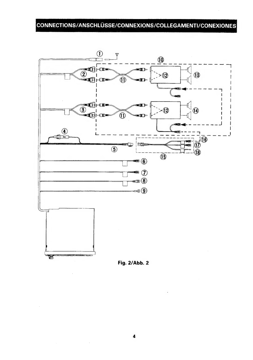
CONNECTIONS/ANSCHLUSSE
/CONNEWGNSIGOLLEGAMENT/CONEIONES
@
Figs3
—F/ADD.
37
oops
eens
Sel
Re
ere
he
be
bea
Ee
anele
Hoe
RE
TESS
O
¥
5
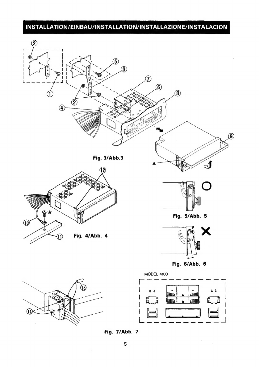
INSTALLATION/EINBAU/INSTALLATION/INSTALLAZIONE/INSTALACION
“ENGLISH”
INTRODUCTION:
5
vgeid
a
Sided
cheb
ae
eile
ate
te
Bt
aah
pe
eet
eae
SS
SIE
Sad
ee
a
ta
6
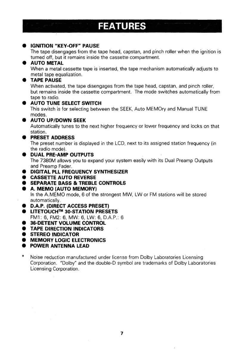
FEATURES
225
ate
asta
ees
a
eit
Aan
gets
eee
a
aheen
hata
cod
mynd
Saetecte
thls
Arty
WOR
die
sida
Sonepat
MIA
OG
Ein,
Ske
oe
6,7
PRECAUTIONS
=..0255.25
-ceet
vie,
eens
Gp
Bet
ae
sath
aa
ave
Rd
ERE
Seth
Mee
a
alg
cee
geht
oe
2
8
CONTROLS.
AND
INDICATORS
-2.2
v5c5s
scveatsiueae
bes
Seach
de.
©
tgs
oa
whan
Spat
Meging.
dadue-p
doth
setae
a
Sa
9
CONNEGTIONS:...
sic
frisecente
Sok
ial
SS
seet
bef
24
ARS
SURE
ELS
area
t
pegged
hea
we
dam
auaeane
nad
nets
10
INSTALLATION
(clon
45
sche
sie,
s
ecg
ilies
eas
Bde
edu
eased
tactte
dare!
Poo
ncrtving
PetB
lcs,
Goh
bee
heegeew
aah
Fk
ee
11
OPERATION.
22-creypiccioneey
fal
nett
Sabet
deabacs
Aca
ghate
SAM
Rae
Wein
akg
Gace
CR
bros,
Aa
Son
Rane
12
—
16
SPEGIFIGATIONS
325.
ccaccracsicticars
Frey
d
Meo ted
cabo
h
Bye
Cony
arn
ale
yera,
HP
Slavens
Slats
Ba
alate
tea
oun
er
kee
17
“DEUTSCH”
EINRUHRUNG
si cd
sub
nash
eae
toate
i,
tage
na
goede
Caan
Sa
td
edie
Gada
iden
sg
18
MERKMALE:
rere.
inal
co
canny
sha
cets
Aupuat
gia?
sueyaita:
afte
&
evavealigh
ana!
Basse,
allie
aetta
2g
lay'e
ah
Gkcd
Gaaawecarardn,
sat
se
18,
19
VORSICHTSMASSREGELN
0.
oscccetoc
dave
ta
din
selges
dads
SAS
aN
ep
RAS
BE
dew
Od
nat
de
ae
ada
s
20
BEDIENUNGSELEMENTE
UND
ANZEIGEN.
.
0.00...
cen
teens
21
ANSCHEUSSE.
5
ccs
ton
oe
ct
a
Mintees,
2
erick
hee.
teh
aa
Rio
weg
dD
epee
opanietdnn
©
eanta
vench
Gamavaiaes,
aah
22
EINBA
Ds
chia
certo
Sip
Lis
wceossa
aun
ahah
s
Qaash
Leb
detbhi
ag
Es
Gea
ets
doen
soa
aye
aye
Mes
Le
anieghe
eg
23
FONCTIONNEMENT
3.
6.i5
cca
ce
Reid
cate
kek
ea
as
cab
dulee
QohGie
es
g.cveie
awed
ace
36
—
40
SPECIFICATIONS
3
ditdiccemsscdions,
aopiud
tote
aoa
wile
ess
LONE
dyed
aoe ETM
gla
eadlnginldungethsna’
QE
tae
heed
y
A
“ITALIANO”
NTRODUZIONE,
06
j.0
Ate
eis
gam
Beck
ateg
eo
e
acolo
SEES
eae
ee
day
a
ee
Magid
42
CARAT
TERISHCHE::
fo.
cise
sty
eracp
costae
roe
ae
SO
Sie
CN
ene
As
a
Pal
dele
dandy
dasa
be
agaceigele
au
eo
42,
43
PRECAUZIONI:
:
io.
eee
tecsten
Sulertties,
Sand
beta
@5
the
OS
Ube
ae
be
ee
be
RA
en
NL
ated
ink
Sed
44
CONTROLEL
ED'INDICATOR:
1:.4.'socseicay
sho0)
Cosa
necyoeat
ohineks
ale
Me
tanner
Be
aybutae
aveltecs
ereldsva,
ee
45
COEREGAMENTH
oho
2
oir
5-25 wees
ats
hoi
wall
Satay
tater
eransties
aba
laine,
Hala,
amanbitaayet
aad
pean,
fips
Gaal
iMate
meee
Th
$a
46
NSTABLAZIONEs
2
lec
2a
te
PEs
erika
ssily
ayo:
lids
daegial
Wile
dana,
wed
pctzawnral
win
alae
to
aeRiphendaoenn
47
FUNZIONAMENTIO:...
osc
ction.
cae
Ra
Daal
Gs
VERSA
av
th
abate
soca
abide,
ai
ili
dive
48
—
52
SPECIRICAZION
esse
iin.
gastio
cette
Rate
ion
aie,
Sin
teased
ar
aia
Wanda
Getenincn
mn
aseee
feb
aia
Bitch
ace
53
“ESPANOL”
INTRODUCCION
(59.3
sc
tbe
SoMa
ae
des
tles
Obs
Lewamed
b
ha
gy
a
eentwnd
Bee
ee
te
54
CARAGTERISTICAS
«.csisch
Uh
cit
te
tn
eines
Ma
dees
eoaennd
te
Searstechelinadt
sar
dtie
Sani
boatelaaeilse
hss
2
Bae
aaaias
54,
55
PRECAUCIONES
5
fee
iad
Rls
sed
clugetny
aie
i
aA
dst
RAV
eh
it
cits
yaadiecdane
aed
Laat
56
CONTROLES
E:INDICADORES
3.0
gnc
aec
ee
tl
at
etna
dads
depyanaielelyo
wid
apiece
Aude
Sae
pad
57
CONEXIONES
2.
3...22
a5.
sche
OM
a
Sales
Bute
en
wnat
Ge
Me
Ee
aah
edad
s
dvd
cota
at
58
INSTALACION
t:.c.
oat
ote
cases
oe
ohne
godt
aaa
FAN
Seale
chisg
Auraads.
BAlqugte
GS
goblet
due
Mlaswen
dl
aca
se
59
OPERAGION:
f
70.020:
dhcnihls
onto!
Mei
eats
eV
bls
ean
Bawa
hada
nla
te
Gales
60
—
64
ESPEGIFICACIONES
nts
cece
itis
Sled
tet
cecs
goats
Uy
ngtlbc
Weal
ans
dk
oe
ones
ve
ag
ayn
aeascmenta
ao
65
@
SYSTEM
CHARTS/SYSTEMAUFBAU/DIAGRAMMES
DU
SYSTEME/DISPOSIZIONI
DEL
SISTEMA/DIA-
GRAMAS'DEL-SISTEMAS
ccogesi8
nee
ae
uts
doers
BAA
AA
Ae
ee
nn
Saeed
Geom
caus
eee
te oe
66,
67