ALTAS AUTO NOVUS Ecoline User manual

š

2 | P a g e
Contents
1At a glance ........................................................................................... 3
1.1 Cockpit......................................................................................... 3
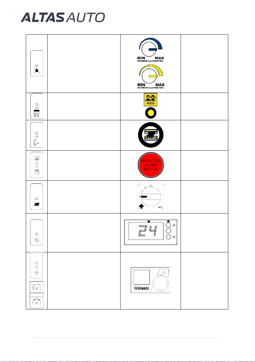
1.2 Additional equipment console...................................................... 3
1.3 Instrument cluster........................................................................ 8
1.4 Novus instrument display............................................................. 9
1.5 General layout of the vehicle ..................................................... 12
2Safety..................................................................................................14
2.1 Emergency exits and safety equipment..................................... 14
2.2 High Voltage.............................................................................. 15
2.3 Acoustic vehicle alerting system (AVAS)................................... 17
2.4 Emergency charging system disconnection............................... 17
3Climate control.....................................................................................18
3.1 Air Conditioning Control............................................................. 18
3.2 Heating system.......................................................................... 19
4Driving and parking..............................................................................23
4.1 Driving ....................................................................................... 23
4.2 Charging.................................................................................... 26
4.3 Parking for short and long durations.......................................... 28
5Instrument display ...............................................................................29
5.1 Overview of the instrument cluster............................................. 29
5.2 Overview of Novus instrument display....................................... 30
6Breakdown assistance.........................................................................36
6.1 Towing....................................................................................... 36
7Technical data.....................................................................................37
7.1 Fuses and relays ....................................................................... 37
7.2 Operating fluids.......................................................................... 44
7.3 Vehicle data............................................................................... 45
8Display messages ...............................................................................47
8.1 Diagnostic trouble codes ........................................................... 47
9Maintenance and care.........................................................................53
9.1 Exploitation and Regular Maintenance Guidelines .................... 53
10 Warranty Conditions............................................................................61
10.1 ALTAS warranty......................................................................... 61
11 Contact information .............................................................................63

3 | P a g e
1 At a glance
1.1 Cockpit
1
Additional equipment console
2
Instrument cluster
3
Novus instrument display
1.2 Additional equipment console
Description of knobs and buttons
Button for switching the
KIDS indication ON / OFF.
“Ramp is
deployed”
indication lamp
(yellow).
Button for switching the
passenger compartment
lightning (OFF / night mode
No. 1 / night mode No. 2).
Button for
resetting the
passenger
STOP alarm.

4 | P a g e
Button for switching the
passenger STOP buttons
active / not active.
Knobs for
adjusting the
intensity of the
passenger
compartment
lightning (night
mode / day
mode).
Button for switching the
display board ON / OFF.
KIDS indication
ON / OFF lamp.
Button for switching the
additional heater* ON /
OFF.
USB socket
charger.
Button for switching the
additional heater** ON /
OFF.
Button for
opening /
closing the
service door.
Button for switching the
cash register ON / OFF.
Air conditioning
system control
panel (see
section 3.1).
Button for switching the
illumination above the
service door ON / OFF.
Temperature
control panel
(see section
3.2).
Button for switching the
ventilator ON / OFF.
Coolant heater
control panel
(see section
3.2).
SET
ON

5 | P a g e
Drive selector.
Display board
control panel
(see below for
possible
options).
* Located in the lowered section below the folding passenger seats.
** Located in the lowered section below the single passenger seat.
NOTE Number of knobs and buttons vary depending on the bus specification.
HANOVER display board control panel
The four keys are all that is required to access the database and carry out all
controller functions. All driver information is shown on the OLED display.
OLED Display
Left Arrow Key
Function/Entry
Key
The
F/E key is a Function & Entry key. Use it to select function.
The
Left arrow key has a dual function. 1 Selecting the next entry digit. 2
Back button for options behind the lock code.
Each press of the up Arrow key increases this code digit’s value by 1.
Each press of the down Arrow key decreases this code digit’s value by 1.
The USB Data Port is used to update the DG3 database and Firmware.
NOTE Refer to the DG3 Controller Quick Start Manual for more information
and instructions how to configure the USB stick for loading.
Up Arrow Key
Down Arrow Key
Data Port (USB)

6 | P a g e
DG3 Drivers Display
There are up to three display lines available on the DG3 controller. The upper
two lines are generally used for destination text, the lower line for
Route/Destination and Advert/Information numbers currently selected. The
display screen can mimic what is displayed on the sign.
DG3 configuration is shown below. It specifies the meaning of the code digits
in each position along the lower display line.
Advert No.
Information No.
Sign Error Indicator.
Making the Selections for your Destination/Route number
How to change your destination numbers is shown below. The same
sequence is also used for setting the route, Info & Advert numbers. Eachpress
of the F/E key shown in point 1 below moves you through the options. These
options are dependent on the configurations selected in Helen.
Example: Setting DG3 Destination Number 35
1. Press until ‘Dest No:’/‘Rte No:’/‘Info No:’/‘Advert No:’ appears
2. Press or key until 3 appears
3. Press once, the display will show 30
4. Press or key until 5 appears (display shows 35)
5. Press to enter the number displayed.
Route No.
Destination No.
Destination text.
(sign mimic on)

7 | P a g e
NOTE Refer to the DG3 Controller Quick Start Manual for more information
how to use other menu options.
MOBITEC display board control panel
Buttons and display on the front plate
The control panel has a “Home”
button for reaching the start menu,
5 functional buttons for the different
sub menus, 4 cursor keys for
navigating / scrolling within the sub-
menus, “OK / Cancel” buttons for
verifying or aborting a menu option,
and an alphanumerical keyboard to
enter data.
NOTE Loading new data, as well as new configuration and software, is
done with the USB flash memory via the USBslot on the front of the control
unit.
The display is divided into 3 areas:
1. Text field: this field shows the
actual information being presented
to the passengers. This information
is automatically changing together
with each change in the system.
2. Status field: this field shows all codes being connected to the actually
served route, e.g. line or destination code. An indicator in the upper right
corner of the display indicates if the control unit receives accurate GPS and
/ or GLONASS data.
3. Functional menu field: this field indicates the actual functions of the
buttons F1-F5.
NOTE Refer to the Mobitec Control Unit MobiMASTER ICU602 User’s
Manual for information on how to update and configure the control unit.

8 | P a g e
1.3 Instrument cluster
Black and white display (see section 5.1)
Color display (see section 5.1)

9 | P a g e
1.4 Novus instrument display
NOTE After starting the vehicle, Novus monitor will load up within 10 seconds.
Home display (see section 5.2, Home)
Economy parameters display (see section 5.2, Economy)

10 | P a g e
Climate control menu (see section 5.2, Climate)
Settings and diagnostic trouble codes menu (see section 5.2, Settings)

11 | P a g e
Charging information display (see section 5.2, Charging)

12 | P a g e
1.5 General layout of the vehicle
Altas Novus Ecoline
1. Energy Storage System (ESS).
2. Electric Motor.
3. Electric Drive System (EDS).
4. Combined Charging System (CCS).
5. Coolant Heater.
6. Power Control Assembly (PCA).
7. Fuel Tank (71 liters).

13 | P a g e
Altas Novus Cityline
1. Energy Storage System (ESS).
2. Electric Motor.
3. Electric Drive System (EDS).
4. Combined Charging System (CCS).
5. Coolant Heater.
6. Power Control Assembly (PCA).
7. Fuel Tank (7 liters).

14 | P a g e
2 Safety
2.1 Emergency exits and safety equipment
Altas Novus Ecoline
Altas Novus Cityline

15 | P a g e
In case of emergency
use emergency exits:
Side windows.
Hammers are placed
near side windows of a
bus. In case of
emergency, remove the
hammer from the holder
and break the window.
Emergency hatch.
Entrance door.
Every seat is equipped with a safety belt. Always fasten your seat belt
correctly before starting a journey. Only a seat belt which is worn correctly
can provide the intended level of protection.
2.2 High Voltage
Precautions on high voltage
Vehicle is equipped with high voltage system components. All components
and wires powered by high voltage are marked orange color or special
warning stickers.
Failure in observing these instructions may result in electric shock, personal
injury or death.

16 | P a g e
Safety disconnector
Safety disconnectors must be disconnected before performing any
maintenance or repair work for high voltage equipment.
NOTE It may be needed to lift the vehicle in order to access the safety
disconnector.
Locate the safety disconnectors on each battery assembly .
To unplug the safety disconnector:
Safety disconnector has a 350A fuse inside the plug. In case of failure, check
the fuse using a multimeter.

17 | P a g e
NOTE Make sure the vehicle is dry and no water or foreign materials will
contaminate the safety disconnector when disconnected.
2.3 Acoustic vehicle alerting system (AVAS)
Theacoustic vehicle alerting system (AVAS) warns other road users about an
approaching electric vehicle.
The AVAS is switched on when the vehicle’s drive system is activated, and
vehicle starts moving.
The AVAS operates until the vehicle reaches 40 km/h speed.
NOTE The volume and audibility of the electronic engine sound may be
restricted by snow or heavy soiling in the area of the front grille. This could
result in accidents.
Before each journey, always check the area of the front grille for heavy soiling
and clean if necessary.
The driver should always expect that the vehicle will not be heard by other
road users despite the AVAS being activated.
2.4 Emergency charging system disconnection
Stop vehicle charging in accordance with the instructions of the charger.
If charger cable cannot be unplugged, press and hold for 3s on the CABLE
STATUS in Novus charging information display (see section 5.2, Charging) to
unlock the charger cable.
If none of the beforementioned methods help to unlock the charger cable, see
Emergency charger cable release instructions (included together with Novus
Operating Instructions).

18 | P a g e
3 Climate control
3.1 Air Conditioning Control
The air conditioning can be turned on only when the electric drive is activated.
With the electric drive turned off, only ventilation is available.
To turn on / off the air conditioning, press A/C button on the climate controller
and set the power manually using the Novus instrument display (see
section 5.2, Climate).
Temperature and fan speed are controlled by the climate controller .
The passenger compartment’s A/C system controller is shown below:
The fan speed is adjusted by turning the control knob .
NOTE The air conditioner needs to be turned on for a few minutes in
wintertime (at least once a week). This will ensure the proper operation of the
air conditioning system.
It is recommended to check the air conditioning system every year in an
authorized repair shop. Change the refrigerant at least once in two years.
Using more air conditioner’s power will decrease the driving range.

19 | P a g e
3.2 Heating system
Turn on / off heating by setting heater's power manually in the Novus
instrument display (see section 5.2, Climate).
Heater’s temperature and fan speed is controlled by climate controller .
NOTE Using more heater's power will decrease the driving range.
Additional coolant heater
Vehicle could be equipped with an additional coolant heater.
The controller is turned on when the vehicle ignition is activated. It controls
the coolant heater automatically when the temperature is set.
Temperature controller functions
▪UP key: when pressed for at least 5 seconds, a manual defrost is
started with programmed duration (in thermostats function). In
programming, it increases the displayed value.
▪DOWN key: in programming, it reduces the displayed value.
▪SET key: when pressed for at least 5 seconds, it displays the SET
POINT temperature value (in thermostats function). In programming,
it saves the programmed new value.
▪LED 1: defrost in operation indicator (in thermostats function).
▪LED 2: relay ON indicator. (in thermostats function). It indicates when
heating is active.
▪LED 2 flashing: programming mode.

20 | P a g e
Set Point Temperature
The factory SET POINT default value is 0 ºC.
▪Press SET key for 5 seconds to display SET POINT. It displays the
current SET POINT value and LED light starts flashing.
▪Press UP or DOWN keys to change SET POINT to the required
value.
▪Press SET key to accept the new SET POINT. The display returns
to the current temperature display status and LED light stops
flashing.
Additional coolant heater could be also controlled by the standard
controller.
Heater's work time could be set manually.
1. Menu name
2. Menu symbol
3. Activated time settings
4. Hour
5. Quick start button with status
display
6. Control knob
Button
Description
Quick start button with status display (backlight).
Control knob (turn/push button) for selection and confirmation
of the selected functions.
This manual suits for next models
1
Table of contents