Altimium AMP250 User manual

AMP250
Mini Audio Amplifier
All Rights Reserved
Version: AMP250_2016V1.1
User Manual

Mini Audio Amplifier
Altimium www.altimium.com
Preface
Read this user manual carefully before using this product. Pictures shown in this manual
is for reference only, different model and specifications are subject to real product.
This manual is only for operation instruction only, not for any maintenance usage. The
functions described in this version are updated till December 2016. Any changes of
functions and parameters since then will be informed separately. Please refer to the
dealers for the latest details.
All product function is valid till 2016-12-2.
Trademarks
Product model and logo are trademarks. Any other trademarks mentioned in this manual
are acknowledged as the properties of the trademark owner. No part of this publication
may be copied or reproduced without prior written consent.
FCC Statement
This equipment generates, uses and can radiate radio frequency energy and, if not
installed and used in accordance with the instructions, may cause harmful interference
to radio communications. It has been tested and found to comply with the limits for a
Class B digital device, pursuant to part 15 of the FCC Rules. These limits are designed
to provide reasonable protection against harmful interference in a commercial
installation.
Operation of this equipment in a residential area is likely to cause interference, in which
case the user at their own expense will be required to take whatever measures may be
necessary to correct the interference
Any changes or modifications not expressly approved by the manufacture would void
the user’s authority to operate the equipment.

Mini Audio Amplifier
Altimium www.altimium.com
SAFETY PRECAUTIONS
To insure the best from the product, please read all instructions carefully before using
the device. Save this manual for further reference.
Unpack the equipment carefully and save the original box and packing material for
possible future shipment
Follow basic safety precautions to reduce the risk of fire, electrical shock and injury
to persons.
Do not dismantle the housing or modify the module. It may result in electrical shock
or burn.
Using supplies or parts not meeting the products’ specifications may cause damage,
deterioration or malfunction.
Refer all servicing to qualified service personnel.
To prevent fire or shock hazard, do not expose the unit to rain, moisture or install this
product near water.
Do not put any heavy items on the extension cable in case of extrusion.
Do not remove the housing of the device as opening or removing housing may
expose you to dangerous voltage or other hazards.
Install the device in a place with fine ventilation to avoid damage caused by
overheat.
Keep the module away from liquids.
Spillage into the housing may result in fire, electrical shock, or equipment damage. If
an object or liquid falls or spills on to the housing, unplug the module immediately.
Do not twist or pull by force ends of the optical cable. It can cause malfunction.
Do not use liquid or aerosol cleaners to clean this unit. Always unplug the power to
the device before cleaning.
Unplug the power cord when left unused for a long period of time.
Information on disposal for scrapped devices: do not burn or mix with general
household waste, please treat them as normal electrical wastes.

Mini Audio Amplifier
Altimium www.altimium.com
Contents
1. Introduction.................................................................................................................1
1.1 Introduction to AMP250 .....................................................................................1
1.2 Features ............................................................................................................1
1.3 Package List......................................................................................................1
2. Panel Description........................................................................................................2
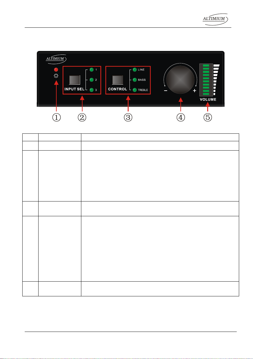
2.1 Front Panel........................................................................................................2
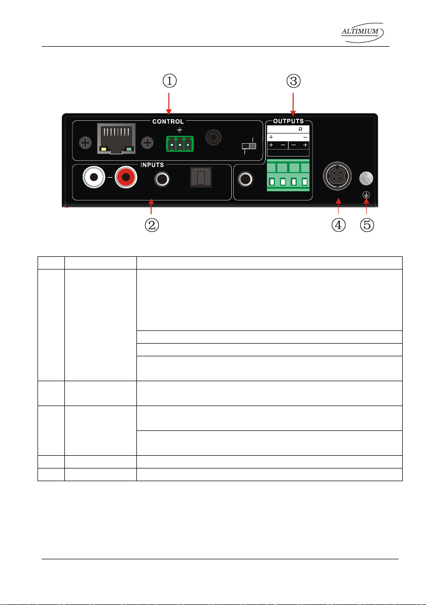
2.2 Rear Panel.........................................................................................................3
3. System Connection.....................................................................................................4
3.1 Usage Precautions............................................................................................4
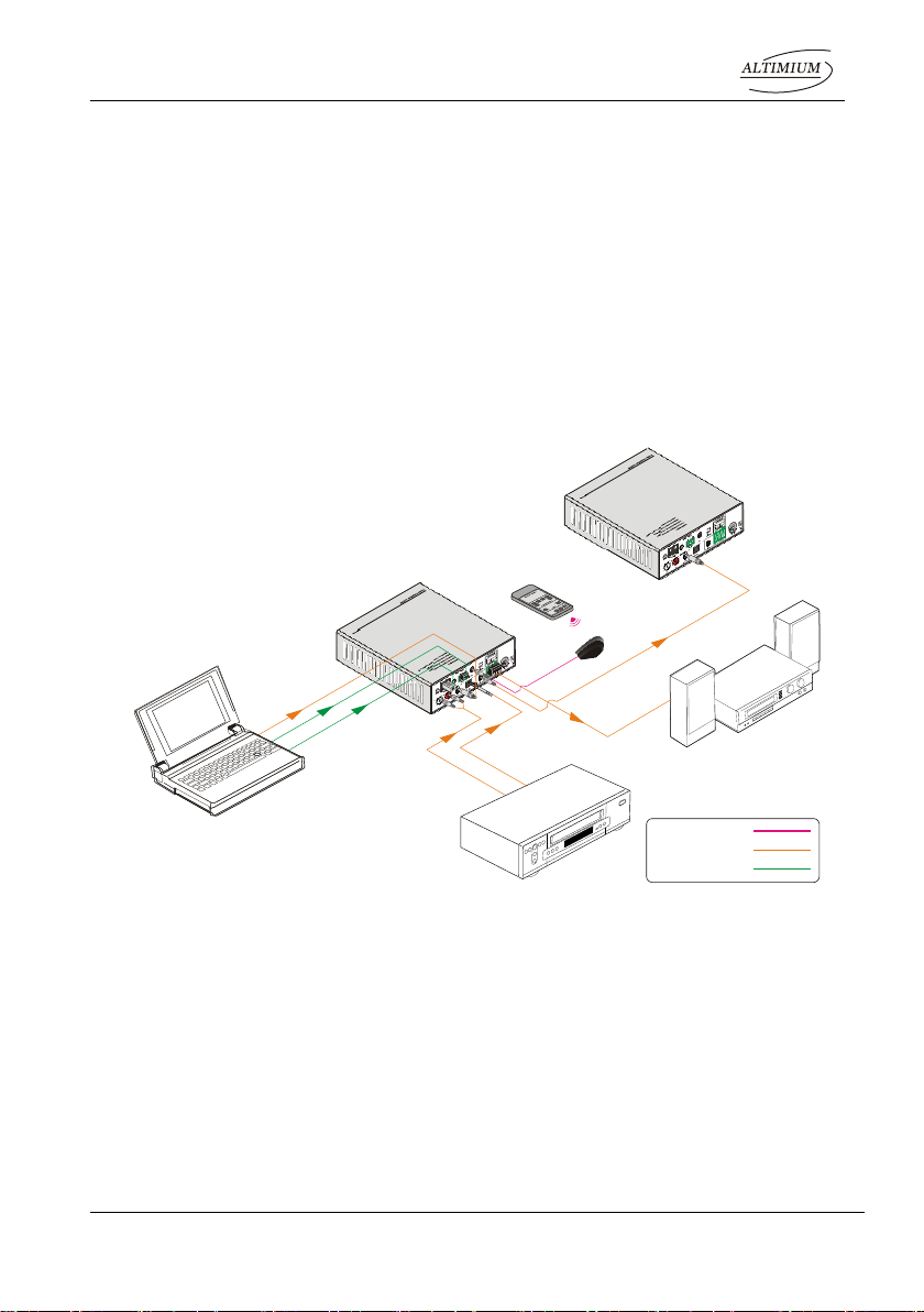
3.2 System Diagram................................................................................................4
3.3 Connection Procedure.......................................................................................4
3.4 Audio Output Connection...................................................................................5
3.4.1 Stereo output (default): 2x50Watt@8Ohm...............................................5
3.4.2 Mono output: 1x100Watt@4Ohm ............................................................5
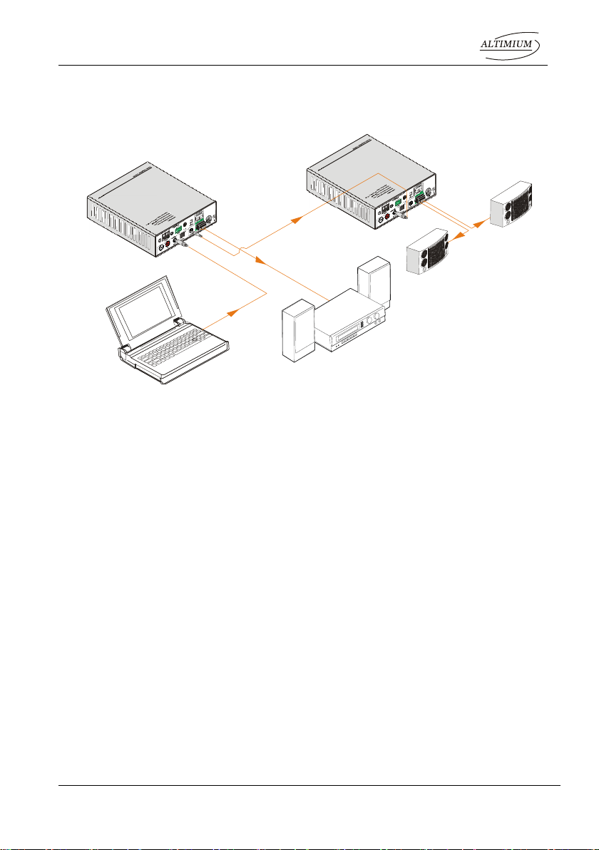
3.5 Loop Connection ...............................................................................................6
3.6 Application.........................................................................................................6
4. System Control...........................................................................................................7
4.1 Front Panel Button Control................................................................................7
4.2 IR Control ..........................................................................................................8
4.3 RS232 Control...................................................................................................9
4.3.1 Installation/uninstallation of RS232 Control Software..............................9
4.3.2 Basic Settings..........................................................................................9
4.3.3 RS232 Communication Commands ......................................................11
4.4 TCP/IP Control.................................................................................................12
4.4.1 Control Modes.......................................................................................12
4.4.2 Control via TCP/IP communication software .........................................13
4.4.3 Control via web-based GUI....................................................................14
4.4.4 Port Management..................................................................................16
5. Specification .............................................................................................................17
6. Panel Drawing ..........................................................................................................18
7. Troubleshooting & Maintenance ...............................................................................19
8. After-sales Service....................................................................................................20

Mini Audio Amplifier
Altimium 1 www.altimium.com
1. Introduction
1.1 Introduction to AMP250
AMP250 is a compact-size digital amplifier (Class-D) with 3 inputs (1 L+R stereo audio,
1 analog audio, 1 optical fiber audio). It features switchable stereo or mono output, and
boasts complete EQ adjustment and intuitive work status display, making it an ideal
addition to a classroom or conference room application.
1.2 Features
3 audio inputs: 1 L+R stereo, 1 analog, 1 optical fiber
Switchable stereo / mono output
Complete EQ management: including LINE, BASS, TREBLE
Easy volume adjustment via a rotary knob
Audio loop output
Intuitive LED indicators for input source, control and volume setting
Controllable via RS232, IR, TCP/IP (optional)
Web-based GUI
Power off memory
1.3 Package List
1 xAMP250
2 x Detachable Mounting Ears
4 x Screws
2 x Pluggable Terminal Blocks (1 3-pin& 1 4-pin)
1 x IR Remote
1 x Power Adapter (DC 36V 2.66A)
1 x User manual
1 x IR Receiver (5V, without carrier)
Please confirm if the product and the accessories are all included, if not, please
contact with the dealers.

Mini Audio Amplifier
Altimium 2 www.altimium.com
2. Panel Description
2.1 Front Panel
Figure 2- 1 Front Panel
No.
Name
Description
①
Power LED
Illuminate red when powered on
②
Input Selection
Press to select any one of the 3 inputs, indicators will light
accordingly
Input 1~3 corresponds to audio sources connected to the 3
audio input ports separately;
1: L+R stereo audio
2: 3.5mm analog audio
3: optical audio
③
Control
Press to select the audio to be controlled, including LINE,
BASS, TREBLE
④
Volume Knob
Press to mute/unmute the audio
Note: after pressed the button to mute the audio, except
pressing it again to restore the audio at the same volume,
users can rotate the knob to enable audio output at
respective volume.
Rotate the knob to adjust volume, volume bars will change
accordingly
Clockwise Rotation: Volume up
Anticlockwise Rotation: Volume down
⑤
Volume Bars
Indicate real-time volume setting, 10 bars in total, no volume
bar will be lighted when the audio is muted
Operation Format: “INPUT SEL”+ “CONTROL”+ “Volume Knob”
Example: To adjust bass audio of input 3, select input 3 -> choose bass -> adjust the
volume knob.

Mini Audio Amplifier
Altimium 3 www.altimium.com
2.2 Rear Panel
Figure 2- 2 Rear Panel
No.
Name
Description
①
CONTROL
TCP/IP: (optional) connect with control device to enable IP
control via web-based GUI& TCP/IP communication
software;
Indicators will blink when connected to control device
and communicated normally
RS232: connect with control device to enable serial control
IR IN: connect with IR receiver to collect infrade signal
Channel Switcher: dial to STEREO or MONO to enable
corresponding output mode
②
INPUTS
Audio inputs area, 3 audio inputs in total, including 1 stereo
audio, 1 analog audio and 1 optical audio
③
OUTPUTS
LOOP: analog audio loop output port, available only when input
signal is L+R stereo audio
Audio Output: including stereo audio (2x50W@8Ω), or mono
output (1x100W@4Ω)
④
DC 36V
Insert DC 36V 2.66A power adapter here
⑤
GND
Connect to grounding
Dial the Channel Switcher to demand status before connecting output device.
Once connected, do not try to change the status while it’s working.
LOOP
3
1
DC 36V
IR INRS232
Tx Rx
AUDIO OPTICALL R
2
TCP/IP 2x50W 8@ Ω
1x100W 4@
STEREO
MONO

Mini Audio Amplifier
Altimium 4 www.altimium.com
3. System Connection
3.1 Usage Precautions
1) System should be installed in a clean environment and has a prop temperature and
humidity.
2) All of the power switches, plugs, sockets and power cords should be insulated and
safety.
3) All devices should be connected before power on.
4) Use straight-thru Cat5e/Cat6 with TIA/EIA T568B terminations to connect TCP/IP
port.
3.2 System Diagram
Figure 3- 1 System Diagram
3.3 Connection Procedure
Step1.Connect audio sources (such as Blue-ray DVD) to INPUT ports of the device with
audio cables;
Step2.Dial the Channel Switcher to the right status, and connect audio output devices
(such as speakers) to audio output port accordingly (Specified in 3.4 Audio
Output Connection).
Step3.(optional) Insert an IR receiver (5V, without carrier) to IR IN to enable IR control.
Step4.(optional) Connect a control device (e.g. a PC) to RS232 port to enable serial
control.
Laptop
Speaker
Audio Amplifier IR Remote
IR Receiver
Audio Amplifier
IR Signal:
AUDIO Signal:
Control Signal:
DVD

Mini Audio Amplifier
Altimium 5 www.altimium.com
Step5.(optional) Connect a control device (e.g. a PC) to TCP/IP port to enable IP
control.
Step6. Plug DC 36V power adaptor to the power port of AMP250.
3.4 Audio Output Connection
3.4.1 Stereo output (default): 2x50Watt@8Ohm
Dial the switcher to STEREO to enable 2 50Watt@8Ohm stereo output mode. Connect
the amplifier regularly (as shown in the following figure):
Figure 3- 2 Stereo Output Connection
3.4.2 Mono output: 1x100Watt@4Ohm
To enable mono 1x100Watt@4Ohm output, dial the switcher to MONO, and connect
output devices as the figure below:
Figure 3- 3 Mono Output Connection
LOOP
3
1
DC 36V
IR INRS232
Tx Rx
AUDIO OPTICALL R
2
TCP/IP 2x50W 8@ Ω
1x100W 4@
STEREO
MONO
Speaker
Speaker
Switch to " STEREO"
STEREO
MONO
LOOP
3
1
DC 36V
IR INRS232
Tx Rx
AUDIO OPTICALL R
2
TCP/IP 2x50W 8@ Ω
1x100W 4@
STEREO
MONO
Speaker
STEREO
MONO
Switch to " MONO"

Mini Audio Amplifier
Altimium 6 www.altimium.com
3.5 Loop Connection
AMP250 boasts a LOOP port for audio signal loop output, max 255 units can be looped
within the same operation system. Connect AMP250 like this:
Figure 3- 4 Loop Connection
Then audio signal sent to the first AMP250 is cascaded to other connected AMP250,
which enables multiple AMP250 share the same audio source.
1. Audio loop output is available only when the 1st AMP250 select input 1/2 as
source.
2. Audio control operations are not available to looped audio signal.
3.6 Application
AMP250 has a good application in various occasions, such as computer realm,
monitoring, big screen displaying, meeting room, education and bank & securities
institution etc.
Laptop
Speaker
Audio Amplifier
Speaker
Speaker
Audio Amplifier

Mini Audio Amplifier
Altimium 7 www.altimium.com
4. System Control
4.1 Front Panel Button Control
Front panel buttons provides direct audio control including input source selection and
audio effect adjustment.
Figure 4- 1 Front Panel Buttons
Operation Format: Input Sel + Control + Volume Knob (indicators and volume bar will
display real-time operation)
Input selection (area ①):
Press button INPUT SEL to switch among the 3 inputs cyclely, relative LED will
light to indicate real-time selection. There are 3 selectable audio sources,
corresponding to the 3 audio input ports on the rear panel separately.
1: L+R stereo audio
2: 3.5mm analog audio
3: optical audio
Control (EQ management) (area ②):
Including LINE, BASS and TREBLE, press button Control to switch among the 3
inputs circularly, relative LED will light to indicate real-time selection.
Volume Knob (area ③):
Clockwise Rotation: Volume up
Anticlockwise Rotation: Volume down
About the Volume Bar (area ④):
Volume bar indicates real-time volume setting, 10 bars in total, the higher the volume is,
the more bars will be illuminated. In different EQ control, volume bar tend to act
differently:
LINE: Line volume can be 0~60, one more volume bar will light when the volume is
turned up by 6.
BASS: bass volume can be 0~10
CONTROLINPUT SEL
1
2
3
LINE
BASS
VOLUME

Mini Audio Amplifier
Altimium 8 www.altimium.com
TREBLE: treble volume can be 0~10
4.2 IR Control
Connect an IR receiver (5V, without carrier) to IR IN port on the rear panel, users are
able to control the amplifier by the included IR remote (see as below):
Figure 4- 2 IR Remote
Input Selection
Unmute
Mute
Volume Control
Including LINE, BASS
and TREBLE volume
adjustment

Mini Audio Amplifier
Altimium 9 www.altimium.com
4.3 RS232 Control
AMP250 boasts a 3-pin pluggable terminal block for serial control. The definition of its
pins is listed in the table below.
No.
Pin
Function
1
N/u
Unused
2
Tx
Transmit
3
Rx
Receive
4
N/u
Unused
5
Gnd
Ground
6
N/u
Unused
7
N/u
Unused
8
N/u
Unused
9
N/u
Unused
Connect AMP250 to the control device (e.g. a PC) with RS232 cable and set the
parameters in the right manner, the control device is capable to control AMP250 via
designed software.
4.3.1 Installation/uninstallation of RS232 Control Software
Installation: Copy the control software file to the computer connected with AMP250.
Uninstallation: Delete all the control software files in corresponding file path.
4.3.2 Basic Settings
Firstly, connect AMP250 with an input device and an output device. Then, connect it with
a computer which is installed with RS232 control software. Double-click the software
icon to run this software.
Here we take the software CommWatch.exe as example. The icon is showed as below:
The interface of the control software is showed as below:

Mini Audio Amplifier
Altimium 10 www.altimium.com
Please set the parameters of COM number, bound rate, data bit, stop bit and the parity
bit correctly, only then will you be able to send command in Command Sending Area.
Parameter Configuration area
Monitoring area, indicates
whether the command
sent works.
Command Sending area
Parameter Configuration area
Monitoring area, indicates
whether the command
sent works.
Command Sending area

Mini Audio Amplifier
Altimium 11 www.altimium.com
4.3.3 RS232 Communication Commands
1) Case-sensitive.
2) “[“, “]”in the commands are only for easy recognition and not necessary in real
operations. Other symbols including “.”“%”are parts of the commands.
3) Feedbacks listed in the column “Feedback”are only for reference, feedbacks may
vary according to different operations.
Communication protocol: Baud rate: 9600; Data bit: 8; Stop bit: 1; Parity bit: none.
Command
Description
Feedback
1A1.
Switch to input 1
A: 1 -> 1
2A1.
Switch to input 2
A: 2 -> 1
3A1.
Switch to input 3
A: 3 -> 1
0A0.
Mute Audio Line out
Mute Audio
0A1.
Unmute Audio Line out
Unmute Audio
600%
Inquire present working status
A: 1 -> 1
Volume: 30
Bass: 0
Treble: 0
601%
Turn up Line volume by 1
Volume of LINE: 51
602%
Turn down Line volume by 1
Volume of LINE: 51
603%
Turn up Bass volume by 1
Bass of LINE: 4
604%
Turn down Bass volume by 1
Bass of LINE: 4
605%
Turn up Treble volume by 1
Treble of LINE: 4
606%
Turn down Treble volume by 1
Treble of LINE: 4
607%
Restore factory default
Factory Default
A: 1 -> 1
Volume: 45
Bass: 5
Treble: 5
610%
Turn up Line volume by 3
Volume of LINE: 54
620%
Turn down Line volume by 3
Volume of LINE: 51
61X%
Turn up Line volume by X
Volume of LINE: 54
62X%
Turn down Line volume by X
Volume of LINE: 54
7[x][x]%
Preset line volume, [xx] can be 00~60, 61
degrees in total.
Volume of LINE: 50
8[x][x]%
Preset the bass level, [xx] can be 00~10,
11 degrees in total.
Bass of LINE: 7

Mini Audio Amplifier
Altimium 12 www.altimium.com
4.4 TCP/IP Control
AMP250 boasts option TCP/IP port for IP control.
Default settings: IP: 192.168.0.178; Subnet Mast: 255.255.255.0; Gateway: 192.168.0.1;
Serial Port: 4001.
IP& gateway can be changed as you need, Serial Port cannot be changed.
Connect the Ethernet port of control device and TCP/IP port of AMP250, and set same
network segment for the 2 devices, users are able to control the device via web-based
GUI or designed TCP/IP communication software.
4.4.1 Control Modes
AMP250 can be controlled by PC without Ethernet access or PC(s) within a LAN.
Controlled by PC without Ethernet access
Connect a computer to the TCP/IP port of the AMP250, and set its network segment to
the same as the AMP250’s.
Controlled by PC(s) in LAN
Connect AMP250, a router and several PCs to setup a LAN (as shown in the following
figure). Set the network segment of AMP250 to the same as the router’s, then PCs
within the LAN are able to control AMP250.
9[x][x]%
Preset the treble level, [xx] can be 00~10,
11 degrees in total.
Treble of LINE: 7
GetIP;
Get the IP of the device
IP: 192.168.0.178
Same network
segment as the
switcher

Mini Audio Amplifier
Altimium 13 www.altimium.com
Follow these steps to connect the devices:
Step1. Connect the TCP/IP port of the AMP250 to Ethernet port of PC with
straight-thru CAT5e/6.
Step2. Set the PC’s network segment to the same as the AMP250’s.
Step3. Set the AMP250’s network segment to the same as the router.
Step4.Set the PC’s network segment to the original ones.
Step5. Connect the AMP250 and PC(s) to the router. PC(s) within the LAN is able to
control the AMP250 asynchronously.
4.4.2 Control via TCP/IP communication software
(Exampled by TCPUDP software)
1) Connect a computer and AMP250 to the same network. Open the TCPUDP
software (or any other TCP/IP communication software) and create a connection,
enter the IP address and port of AMP250 (default IP: 192.168.0.178, port:4001):
2) After connect successfully, we can enter commands to control the AMP250, as

Mini Audio Amplifier
Altimium 14 www.altimium.com
below:
4.4.3 Control via web-based GUI
AMP250 provides with built-in GUI for convenient TCP/IP control. GUI allows users to
interact with AMP250 through graphical icons and visual indicators.
Type 192.168.0.178 (default IP, changeable via GUI) in your browser, it will enter the
log-in interface shown as below:
Figure 4- 3 Log-in interface
GUI interfaces can be displayed in Chinese/ English, selectable by clicking 中文/
ENGLISH.
Type the right name and password in relative column:
Here you will receive the
feedback when a command
is sent.
Enter your command here.
Commands are the same with
RS232 commands listed in 4.3.3
RS232 Communication
Commands

Mini Audio Amplifier
Altimium 15 www.altimium.com
Name: admin; Password: admin (default setting, changeable via GUI)
Click LOGIN, it will show the audio selection interface as shown below:
Audio Selection:
Figure 4- 4 Network Control
In this interface, you can:
Select input
Mute/ Unmute
LINE/ BASS/ TREBLE control: drag the volume dot to turn down/ up the
corresponding volume
Switch to network configuration interface by clicking NETWORK
Network Configuration:
Figure 4- 5 Audio Selection
In this interface, you can:

Mini Audio Amplifier
Altimium 16 www.altimium.com
Configure network settings:
IP: support DHCP and Static IP, choose demanded state by clicking the button
DHCP: IPAddress, subnet mask and gateway are fixed in this mode.
Static IP: set IPAddress, subnet mask and gateway manually. Make sure the
IP is different with control device’s.
Modify password: type in new password in the column, max at 5 numbers/
letters
Inquire software version
Switch to audio selection interface by clicking AUDIO SEL
If there is any modification in this interface, press Save to restore the settings, or
press Cancel to withdraw. Click ADUIO SEL to return to NETWORK interface.
Clear the cache of the browser beforehand to ensure reliable GUI operation.
4.4.4 Port Management
Type the designed website 192.168.0.178:100 (Default, changeable via GUI) in your
browser. Enter correct username and password (same with GUI name and password) to
log in the WebServer:
Here is the main configuration interface of the WebServer:
In this interface, you can:
Change website display language
Modify network settings: Go to Internet Settings -> WAN
Upgrade TCP/IP module: Go to Administration -> Upload Program -> Select
program file -> Start upgrading
Reboot the device after upgrading.
Table of contents
Other Altimium Amplifier manuals