Altinex Cable-Nook CNK600 User manual

CNK600 Cable-Nook®Interconnect Box User’s Guide
400-0643-001
1
Welcome!
We greatly appreciate your purchase of the CNK600 Cable-Nook
Interconnect Box. We are sure you will find it reliable and simple
to use. Superior performance for the right price, backed by solid
technical and customer support is what Altinex offers.
We are committed to providing our customers with Signal
Management Solutions®to the most demanding audiovisual
installations at competitive pricing and we welcome you to join the
ranks of our many satisfied customers throughout the world.
1. Precautions and Safety Warnings
Please read this manual carefully before using your CNK600.
Keep this manual handy for future reference. These safety
instructions are to ensure the long life of your CNK600 and to
prevent fire and shock hazards. Please read them carefully and
heed all warnings.
1.1 General
Qualified ALTINEX service personnel or their authorized
representatives must perform all service.
1.2 Installation
For best results, place the CNK600 Cable-Nook
Interconnect Box in a dry area away from dust and
moisture.
To prevent fire or shock, do not expose this unit to water or
moisture. Do not place in direct sunlight, near heaters or
heat-radiating appliances, or near any liquid. Exposure to
direct sunlight, smoke, or steam can harm internal
components.
Handle carefully; dropping or jarring can damage the unit.
Never place fingers inside the openings in the back of the
unit. This action could cause serious injury because of the
sharp edges inside.
Do not place heavy objects on top of the CNK600.
Install all cables according to the instructions.
1.3 Cleaning
Clean surfaces with a dry cloth. Never use strong
detergents or solvents such as alcohol or thinner. Do not
use a wet cloth or water to clean the unit.
1.4 FCC Notice
This device complies with Part 15 of the FCC Rules.
Operation is subject to the following two conditions: (1) This
device may not cause harmful interference, and (2) this
device must accept any interference received, including
interference that may cause undesired operation.
This equipment has been tested and found to comply with
the limits for a Class A digital device, pursuant to Part 15 of
the FCC Rules. These limits are designed to provide
reasonable protection against harmful interference when the
equipment is operated in a commercial environment. This
equipment generates, uses, and can radiate radio frequency
energy and if not installed and used in accordance with
instructions found herein, may cause harmful interference to
radio communications. Operation of this equipment in a
residential area is likely to cause harmful interference in
which case the user will be required to correct the
interference at his own expense.
Any changes or modifications to the unit not expressly
approved by Altinex, Inc. could void the user’s authority to
operate the equipment.
2. Installation Procedures
Note: Download and read the entire online manual to become familiar with the CNK600
and for detailed installation instructions
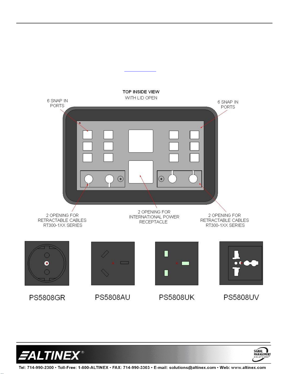
Step 1. Cut an opening into the table for the CNK600. Refer to the Altinex website at
www.altinex.com for table cutout requirements template. Table thickness can be
3.5 in (89 mm) or less. Always confirm dimensions before cutting; specification
can change.
Step 2. Assemble the SP2116SC/SP2117SC plates with snap-in cables and
install plates into the CNK600.
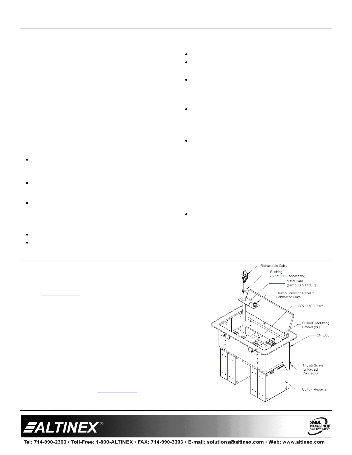
Step 3. Install any retracts unit to the CNK600 body. Cables feed through the
CNK bottom plate, retract metal panels, and up through bushing as
shown. Connect retract metal panel to the SP plate using thumb screws
attached. Slide bushings into plate openings to provide cable retention.
Step 4. Insert assembled CNK600 into opening. Tighten mounting screws to the
table from the top using provided Arm Hex–L key.
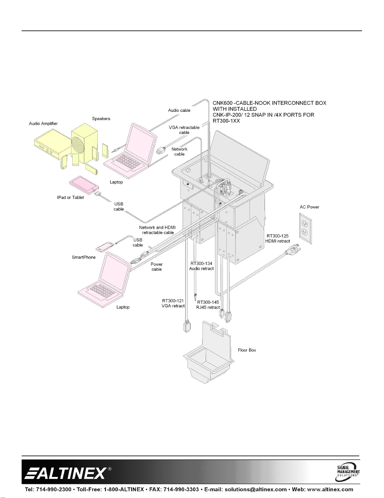
Step 5. Connect cables to their corresponding inputs under the surface.
3. Limited Warranty/Return Policies
Please see the Altinex website at www.altinex.com for details on warranty and return policies.

CNK600 Interconnect Box User’s Guide
400-0643-001
2
4. Technical Specifications
Specifications are subject to change. See www.altinex.com for up-to-date information.
Features/Description
CNK600
Inputs
Video/Audio
n/a
Outputs
Video/Audio
n/a
Compatibility
Cable-Nook Standard and
Customizable Plates
SP2116SC
SP2117SC
Snap-In Connectors
All Altinex Snap-In
Connectors
Retractable cables
All Altinex Retractable Cables
Accessories Included
Mounting Hardware
-Mounting screws(4pcs)
-Mounting Brackets(4pcs)
(attached to the unit)
- Arm Hex L- Key
Table 1. CNK600 General
Mechanical
CNK600
Minimum Table Thickness
0.5 in (13 mm)
Maximum Table Thickness
3.5 in (89 mm)
Housing Dimensions
Height
5.8 in (147 mm)
Width
9.3 in (236 mm)
Depth
5.1 in (130 mm)
Bezel Dimensions (surface)
Width
11.1 in (282 mm)
Depth
7.0 in (178 mm)
Color: CNK600
CNK600S
Black
Brushed Aluminum
Material
Aluminum
T Operating
10 C-35 C
T Maximum
50 C
Humidity
90 non-condensing
MTBF (calculations)
40,000 hrs. (min.)
Table 2. CNK600 Mechanical

CNK600 Interconnect Box User’s Guide
400-0643-001
3
5. About Your CNK600
Installs easily into tabletop
Convenient mounting from top of table
Easy access to cable ends or fixed connectors
Simple, cost-effective interconnect solution
Sold as an empty unit
Pre-configured customizable plates SP2116SC or SP2117SC available
Ten-year warranty
The CNK600 is a simple, effective way of hiding/storing multimedia cables and connectors when not in use. It is designed for
boardrooms and conference rooms. Cables remain connected to a presentation system enabling the user to access connections to AC
power, video, audio, and other media sources.
The CNK600 Cable-Nook is designed for use with tables ranging from half an inch to 3.5 in thick. The height of the interior shelf can
also be adjusted for different depths. The CNK600 comes in a standard matte black color; the CNK600S is brushed aluminum.
The modular Cable-Nook uses a trapdoor type lid that remains flush with the table when not in use. To access the cables or
connectors, simply lift the lid and pull the cable ends out, or plug cables into fixed connectors. The closed lid has an opening that allows
cables to be used with the lid closed. After the presentation, the cable ends are returned to the Cable-Nook for safe storage.
Cables feed through the Cable-Nook to the underside of the table, enabling connection to the presentation system.
The CNK600 has convenient mounting that can be done from the top of the table using the hex-L-key provided. The CNK600 may be
ordered with either of the all-purpose, pre-configured customizable plates SP2116SC or SP2117SC. Plates are mounted directly to
CNK600 chassis using provided with plates 4 screws.
The CNK600 is designed such that retractable cables can be mounted directly to the unit without any additional mounting brackets. The
CNK600 body has thumb screws for retract connections eliminating the need for additional tools.

CNK600 Interconnect Box User’s Guide
400-0643-001
4
6. Application Diagrams
Diagram 1: Typical Setup

CNK600 Interconnect Box User’s Guide
400-0643-001
5
Diagram 2: Dimensions Top and Front

CNK600 Interconnect Box User’s Guide
400-0643-001
6
Diagram 3: Side View Dimensions

CNK600 Interconnect Box User’s Guide
400-0643-001
7
Diagram 4: SP2116SC plate
The CNK600 can be customized using the SP2116SC Plate.
The SP2116SC plate offers dual 12 Amp AC sockets along with 2 USB ports that deliver up to 3A of charging power. The USB charger
has an LED to indicate power availability. The plate also has 12 ports for snap in cables that can be customized based on the
customer’s requirements. In addition, the SP2116SC plate is designed to be used with up to 4 of any combination of Altinex retractable
cables. Unused snap ins and retract opening may be covered with provided as accessories plugs.
Shown below is the SP2116SC top view. See our website at www.altinex.com for a complete list of available customizable snap-in
connectors and available retract cables.

CNK600 Interconnect Box User’s Guide
400-0643-001
8
Diagram 5: SP2117SC Plate (International)
International power outlets are accommodated using the SP2117SC Plate.
The SP2117SC plate offers custom dual international AC sockets and 12 ports for snap in cables that can be customized based on the
customer’s requirements. In addition, the SP2117SC plate is designed to be used with up to 4 of any combination of Altinex retractable
cables. Unused snap ins and retract opening may be covered with provided as accessories plugs.
Shown below is SP2117SC top view. See our website at www.altinex.com for a complete list of available customizable snap-in
connectors and available retract cables.

CNK600 Interconnect Box User’s Guide
400-0643-001
9
Diagram 6: Retractable Cables Mounting

CNK600 Interconnect Box User’s Guide
400-0643-001
10
7. Operation
7.1 Accessing the CNK600
The CNK600 cover opens easily and remains open until all the
cables are connected.
The cover should be closed with the cables routed through the
opening in the cover to prevent damage to the unit and cables.
7.2 Power/Signal Connections
Connect external devices to the appropriate connector from the
CNK600. Remember, the devices plugged into the AC power
connectors should not draw more than the rated values of the
cables and/or circuit.
8. Troubleshooting Guide
The CNK600 supplied was carefully tested and no problems
were detected. However, we would like to offer the following
suggestions:
Please make sure that the highest quality network
cables are used.
Make sure that no cable or power cord is damaged or
pinched. If there has been damage, do not use the
CNK600. Please call the Altinex Customer Service
Department at (714) 990-2300 to have the unit
repaired.
Other Altinex Enclosure manuals