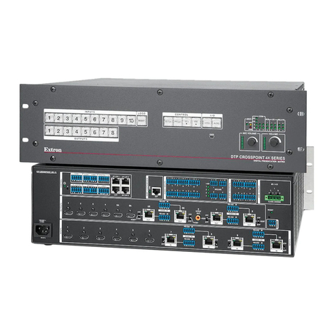
Kramer VS-1616D-MD User manual

KRAMER ELECTRONICS LTD.
USER MANUAL
MODEL:
VS-1616D-MD
16x16 Digital Matrix Switcher
P/N: 2900-300434 Rev 2


VS-1616D-MD – Contents
i
Contents
1Introduction 1
2Getting Started 3
2.1 Achieving the Best Performance 3
2.2 Safety Instructions 4
2.3 Safety Instructions (Laser) 4
2.4 Compliance with Leakage Current Requirements 4
2.5 Recycling Kramer Products 5
2.6 Medical Electrical Equipment (IEC 60601-1) 5
3Overview 6
3.1 About Fast Switching 7
3.2 About HDBaseT™ Technology 8
3.3 About the Power Connect™ Feature 8
4Defining the VS-1616D-MD 16x16 Digital Matrix Switcher 9
5Installing in a Rack 14
6Connecting the VS-1616D-MD 15
6.1 Card Limitations 16
6.2 Port Numbering 17
6.3 Serial Data on DGKat Plus RS-232 Cards 19
6.4 Connecting to the VS-1616D-MD via RS-232 20
6.5 Connecting to the VS-1616D-MD via Ethernet 20
7Operating Your Video Matrix Switcher 24
7.1 Startup Display 24
7.2 Using the Selector Buttons 25
7.3 Confirming Actions 26
7.4 Switching Actions 27
7.5 Locking the Front Panel Buttons 30
8Using the Configuration Menus 31
8.1 Using the Setup Menu 32
8.2 Using the Config Menu 37
9Configuring the Number of Installed Input and Output Ports 61
10 Installing and Using the Test Module to Troubleshoot Video Problems 62
10.1 Installing the Test Module 62
10.2 Setting the Resolution of the Generated Video 63
10.3 Setting the Pattern of the Generated Video 64
10.4 Using the Test Module to Troubleshoot Video Problems 64
11 Hardware Installation Instructions 67
11.1 I/O Card Installation 67
12 Upgrading the VS-1616D-MD Firmware 70
13 Technical Specifications 71
14 Default Communication Parameters 74
15 Label Information 75
16 Factory Default EDID 76
16.1 DVI Input Card 76
16.2 HDCP Input Card 77
16.3 HDMI Input Card 79
16.4 HDMI plus Audio Input Card 81

ii
VS-1616D-MD - Introduction
16.5 DVI Dual Channel Input Card 83
16.6 DGKat Input Card 85
16.7 HDBaseT Input Card 87
16.8 VGA Input Card 89
17 Communication Protocol 3000 91
17.1 Kramer Protocol 3000 Syntax 91
17.2 Table of Protocol 3000 Commands 94
18 Communication Protocol 2000 95
Figures
Figure 1: VS-1616D-MD Front Panel Numeric Keypad 9
Figure 2: VS-1616D-MD 16x16 Digital Matrix Switcher Front Panel 10
Figure 3: VS-1616D-MD 16x16 Digital Matrix Switcher Rear Panel 12
Figure 4: Connecting the VS-1616D-MD 16x16 Digital Matrix Switcher 15
Figure 5: Sample Port Numbering 17
Figure 6: EDID Numbering Assignment 19
Figure 7: DGKat Card Serial Data Transmission 19
Figure 8: Local Area Connection Properties Window 21
Figure 9: Internet Protocol Version 4 Properties Window 22
Figure 10: Internet Protocol Version 6 Properties Window 22
Figure 11: Internet Protocol Properties Window 23
Figure 12: Default Startup Status Display Sequence 24
Figure 13: Menu Tree 31
Figure 14: Resolution DIP-switch 63
Figure 15: Signal Paths for Isolating Problems 64
Figure 16: Inserting the Card into a Slot 67
Figure 17: Card Handles 68
Figure 18: Device Label 75

VS-1616D-MD - Introduction
1
1 Introduction
Welcome to Kramer Electronics! Since 1981, Kramer Electronics has been
providing a world of unique, creative, and affordable solutions to the vast range of
problems that confront video, audio, presentation, and broadcasting professionals
on a daily basis. In recent years, we have redesigned and upgraded most of our
line, making the best even better!
Our 1,000-plus different models now appear in 14 groups that are clearly defined
by function: GROUP 1: Distribution Amplifiers; GROUP 2: Switchers and Routers;
GROUP 3: Control Systems; GROUP 4: Format/Standards Converters; GROUP 5:
Range Extenders and Repeaters; GROUP 6: Specialty AV Products; GROUP 7:
Scan Converters and Scalers; GROUP 8: Cables and Connectors; GROUP 9:
Room Connectivity; GROUP 10: Accessories and Rack Adapters and GROUP 11:
Sierra Video Products; GROUP 12: Digital Signage; and GROUP 13: Audio, and
GROUP 14: Collaboration.
Congratulations on purchasing your Kramer VS-1616D-MD 16x16 Digital Matrix
Switcher which is ideal for the following typical applications:
Professional display systems requiring video signal routing
Broadcast, presentation and production facilities, as well as monitoring in
large duplication systems
Rental/staging applications
Note: Throughout this user manual the chassis configuration is shown with 16 DVI
inputs and 16 DVI outputs as a representation only. The following cards are
available and may be mixed in the same chassis:
Analog audio plus digital audio
DGKat plus RS-232 (HDCP)
DisplayPort plus analog audio
DVI
DVI (HDCP)
DVI dual link

2
VS-1616D-MD - Introduction
HDMI (HDCP)
HDMI (over 4LC fiber optic cable) with 610 module
HDMI (over SC fiber optic cable) with 670 module (HDCP), see note below
HDMI (over HDBaseT) plus IR, RS-232 and Ethernet (HDCP)
HDMI plus analog audio (HDCP)
HDMI UHD plus analog audio (HDCP)
HDMI plus digital audio (HDCP)
HDMI output scaler (HDCP)
HDMI UHD (over HDBaseT 70m) plus IR and RS-232 (HDCP)
SDI plus analog audio
Test card plus analog audio embedding/de-embedding
VGA
VGA plus analog audio
Note: The HDMI over fiber optic with 670 module cards are fully compatible with
the Kramer 670T/670R and 671T/671R HDMI/DVI transmitters and receivers for
non-HDCP content.

VS-1616D-MD - Getting Started
3
2 Getting Started
The following symbols are used in this manual:
Warning:
Indicates a possible hazard to life or serious injury to
persons
Caution:
Recommended procedure which if not followed may
result in damage to the equipment or injury to persons
We recommend that you:
Unpack the equipment carefully and save the original box and packaging
materials for possible future shipment
Review the contents of this user manual
Go to http://www.kramerav.com/downloads/VS-1616D-MD to check for up-
to-date user manuals, application programs, and to check if firmware
upgrades are available (where appropriate).
2.1 Achieving the Best Performance
To achieve the best performance:
Use only good quality connection cables to avoid interference, deterioration
in signal quality due to poor matching, and elevated noise levels (often
associated with low quality cables)
Do not secure the cables in tight bundles or roll the slack into tight coils
Avoid interference from neighboring electrical appliances that may adversely
influence signal quality
Position your Kramer VS-1616D-MD away from moisture, excessive sunlight
and dust
This equipment is to be used only inside a building. It may be connected
only to other equipment that is installed inside a building.

4
VS-1616D-MD - Getting Started
2.2 Safety Instructions
Warning:
No operator serviceable parts inside the unit
Warning:
Use only the Kramer Electronics input power wall
adapter that is provided with the unit.
Warning:
Disconnect the power and unplug the unit from the wall
before installing
Warning:
To avoid risk of electric shock, this equipment must only
be connected to a supply mains with protective earth
Warning:
No modification of this equipment is allowed
Warning:
Do not install this equipment in a patient environment
2.3 Safety Instructions (Laser)
Warning:
Class 1 laser product
Invisible laser radiation present
Avoid long-term viewing of laser
Avoid the use of magnifying viewing aids or instruments
(such as binoculars, telescopes, microscopes and
magnifying lenses, but not spectacles or contact lenses)
Avoid placing optical devices in the emitted beam that
could cause the concentration of the laser radiation to be
increased
2.4 Compliance with Leakage Current Requirements
To ensure compliance with leakage current requirements in medical systems, the
following connections between input and output connectors are allowed:
Non-optical communication—Medical to medical, non-medical to
non-medical, where:
Medical—Device certified according to IEC 60601-1
Non-medical—Device certified according to other standard(s)
Optical communication—No restrictions

VS-1616D-MD - Getting Started
5
2.5 Recycling Kramer Products
The Waste Electrical and Electronic Equipment (WEEE) Directive 2002/96/EC
aims to reduce the amount of WEEE sent for disposal to landfill or incineration by
requiring it to be collected and recycled. To comply with the WEEE Directive,
Kramer Electronics has made arrangements with the European Advanced
Recycling Network (EARN) and will cover any costs of treatment, recycling and
recovery of waste Kramer Electronics branded equipment on arrival at the EARN
facility. For details of Kramer’s recycling arrangements in your particular country
go to our recycling pages at http://www.kramerelectronics.com/support/recycling/.
2.6 Medical Electrical Equipment (IEC 60601-1)
In the modern medical environment remote access is essential, for example, to
transfer clinical data between doctors and to train to medical students. The
VS-1616D-MD is certified according to the IEC 60601-1, Clause 2.1.3, Medical
Electrical Equipment, Part 1: General Requirements for EMC standard which is
required when accessory devices are used at locations where medical personnel
and patients are present.
The VS-1616D-MD constitutes an optional component that can be considered
necessary and suitable as part of medical equipment or for use as part of a
medical system to provide real time simultaneous video feeds to those present at
the local medical environment and at remote locations. In this environment, the
product can be added to the system ONLY if the connecting equipment has been
evaluated and meets the IEC 60601-1 safety standards. Note, that when attaching
accessory devices to a digital or analog interface, they must comply with the IEC
standard for which they are used: Safety Standard (IEC 60601-1), Information
Technology equipment (IEC 60950-1 (2ed)).

6
VS-1616D-MD - Overview
3 Overview
The Kramer VS-1616D-MD is a high performance matrix switcher chassis that
supports up to 16 x 16 ports. It features a very high bandwidth of up to 3.2Gbps
(for the chassis only, effective bandwidth of the system depends on the I/O cards)
that ensures transparent performance even in the most critical applications. The
cards re-clock and equalize the signals and the chassis can route any or all inputs
to any or all outputs simultaneously.
For maximum bandwidth supported by each type of card see the Technical
Specifications in Section 13.
The VS-1616D-MD is highly configurable–you can add or remove inputs and
outputs independently in groups of four and mix different types of input/output
cards in the same chassis up to 16 x 16. For example, you can configure a device
as a 4 x 12 or a 16 x 8 matrix switcher to exactly suit your needs.
The VS-1616D-MD features:
Full 16 x 16 non-blocking matrix array to switch any of the 16 input digital
signals to any or all outputs (with limitations, see Section 6)
Kramer Core™—flexible infrastructure conversion. Copper, fiber or Twisted
Pair, all can be used at the same time according to input/output module
selection. The matrix receives signals from compatible Kramer transmitters,
automatically converts between available infrastructure options and sends
the signals to compatible Kramer receivers
Fast switching on outputs to reduce or remove switching delay
A default EDID (Extended Display Identification Data) for each input
EDID Capture –Copies and stores the EDID from a display device
EDID PassThru –Passes EDID/HDCP signals from source to display
Non-volatile EDID storage

VS-1616D-MD - Overview
7
Kramer Core™—flexible infrastructure conversion. Copper, fiber or Twisted
Pair, all can be used at the same time according to input/output module
selection. The matrix receives signals from compatible Kramer transmitters,
automatically converts between available infrastructure options and sends
the signals to compatible Kramer receivers
Equalization and re-clocking on all card types
Easy access to 59 preset memory locations for quick access to user-defined
setups
The Kramer 2000 Protocol for serial control
A lock function to prevent tampering with the front panel
A 40 character by 2 line LCD that shows the operational status or the
configuration menu
You can operate the VS-1616D-MD via the front panel buttons or remotely via:
RS-232 serial commands transmitted by a touch screen system, PC or other
serial controller
Ethernet over a LAN
The infrared remote control transmitter
Kramer K-Router Plus software application
The VS-1616D-MD is a sophisticated device but has been designed to be as
simple as possible to operate. Due to space limitations on the front panel a keypad
substitutes for 64 individual input/output selector buttons. For details of how to
route inputs to outputs, see Section 6. The VS-1616D-MD is housed in a 19" rack-
mountable enclosure.
3.1 About Fast Switching
Older display devices required a longer time between the loss of one digital signal
and the introduction of another, as well as a physical disconnection of the
interconnecting cable in order to be able to detect and adjust to the new video
attributes and parameters. Normal switching, therefore, introduced a 5V signal
disconnection along with a delay in switching. Many newer display devices
however, are now capable of accepting “on-the-fly” switching.

8
VS-1616D-MD - Overview
Depending on the display device in use, the VS-1616D-MD allows for fast
switching (minor reset and the connection kept alive) and extra fast switching (no
reset and the connection kept alive), see Section 8.2.4. Using the fast and extra
fast switching modes allows for fraction-of-a-second switching times when using
high performance display devices or when using a scaler on the video output.
3.2 About HDBaseT™ Technology
HDBaseT™ is an advanced all-in-one connectivity technology (supported by the
HDBaseT Alliance). It is particularly suitable in the consumer home environment
as a digital home networking alternative where it enables you to replace numerous
cables and connectors by a single LAN cable used to transmit, for example,
uncompressed full high definition video, audio, IR, as well as various control
signals.
The HDBaseT products described in this user manual are HDBaseT
certified.
3.3 About the Power Connect™ Feature
The Power Connect™ feature means that the VS-1616D-MD can supply power
over the TP cable to compatible DGKat devices (for example, the TP-573 or
TP-574) when the devices are within 90m (270ft) of each other. The Power
Connect™ feature applies as long as the cable can carry power and the distance
does not exceed 90m on standard TP cable. For longer distances, use heavier
gauge cable (TP cable is still suitable for the video/audio transmission, but not for
feeding power at these distances).

VS-1616D-MD - Defining the VS-1616D-MD 16x16 Digital Matrix Switcher
9
4 Defining the VS-1616D-MD 16x16 Digital
Matrix Switcher
Figure 1, Figure 2 and Figure 3 define the VS-1616D-MD.
Figure 1: VS-1616D-MD Front Panel Numeric Keypad
Front Panel Numeric Keypad Labels
#
Feature
Function
1
◄ (Backwards)
Press to shift the sliding window to the right (The
LCD display is large enough to show only 13
cross-points out of a total of 32)
2
1, 2, 3, 4, 5, 6, 7, 8, 9, 0
Numeric keypad, 1 to 0
3
► (Forward)
Press to shift the sliding window to the left

Figure 2: VS-1616D-MD 16x16 Digital Matrix Switcher Front Panel
10
VS-1616D-MD –Defining the VS-1616D-MD 16x16 Digital Matrix Switcher

VS-1616D-MD -
11
VS-1616D-MD –Defining the VS-1616D-MD 16x16 Digital Matrix Switcher
11
#
Feature
Function
1
Double-
function
Selector
Button
Area
Menu
Button
Functions
ESC
Press to exit the current operation
2
EDID
Press to assign EDID channels
3
STO
Press to store the current setup in a preset. After pressing the MENU button, this button lights
and is enabled
4
ALL
Press to connect an input to all outputs. After pressing the MENU button, this button lights and is
enabled
5
OFF
Press to turn off an output. After pressing the MENU button, this button lights and is enabled
6
RCL
Press to recall a preset. After pressing the MENU button, this button lights and is enabled
7
DELAY
Press to set the delay between confirming an action and the execution of the action
8
ENT
Press to complete the input-output setup when using a one-digit number instead of two digits.
Press to enter the options in a setup menu. (For example, to enter input 5, you can either press
05 or 5, ENT)
9
BREAKAWAY Button
Press to exit a Menu (see Section 8)
10
DEFAULT SETUP Button
Press to recall the default setup (see Section 7.4.5)
11
OUTPUTS/INPUTS LCD Display
Displays the outputs (upper row) switched to the selected inputs (lower row), (see Section 7.1).
Displays user interface messages and menus
12
IR Receiver
Infrared remote control sensor
13
IR LED
Lights yellow when receiving commands from the IR remote control transmitter
14
TAKE Button
Press to confirm actions (see Section 7.3.2)
15
MENU Button
Press once to enable the ALL, OFF STO and RCL buttons (see Section 8). Press again to enter
the configuration menu (see Section 8.2).
When in a Menu, press to cycle through the menu items
16
LOCK Button
Press and hold for approximately 2 sec to lock/unlock the front panel buttons (see Section 7.5)

Figure 3 shows DVI cards installed as an example.
Figure 3: VS-1616D-MD 16x16 Digital Matrix Switcher Rear Panel
12
VS-1616D-MD –Defining the VS-1616D-MD 16x16 Digital Matrix Switcher

VS-1616D-MD -
13
VS-1616D-MD –Defining the VS-1616D-MD 16x16 Digital Matrix Switcher
13
#
Feature
Function
21
AC Mains Power Module
Fuse holder and power cord socket. Connect to the AC mains supply
22
IN 1~16 Connectors
Connect to the relevant video sources, depending on the cards installed (1 to 16, see Section 6)
23
IN 17~32 Connectors
Connect to the relevant video sources, depending on the cards installed (17 to 32, see Section 6)
24
TEST Module
Signal generator module for testing video outputs (see Section 10)
25
RESOLUTION DIP-switches
Set the resolution for video generated by the Test module (see Section 10.2)
26
RS-232 9-pin D-sub Port
Connects to the remote operation PC or remote controller (see Section 6.2)
27
NET Ethernet RJ-45
Connector
Connect to a PC or controller via the Ethernet LAN (see Section 6.5).
The LINK LED flashes when communication is active. The POWER LED lights when the interface
receives power
28
OUT 1~16 Connectors
Connect to the relevant video acceptors, depending on the cards installed (1 to 16, see Section 6)
29
OUT 17~32 Connectors
Connect to the relevant video acceptors, depending on the cards installed (17 to 32, see Section 6)
30
PATTERN Button
Press the button repeatedly to change the video pattern generated by the Test module (see
Section 10.3)
31
Test Module Output
Connector
Connect to one of the relevant video inputs to aid in troubleshooting (see Section 10.4)

14
VS-1616D-MD - Installing in a Rack
5 Installing in a Rack
This section provides instructions for rack mounting the unit.

VS-1616D-MD - Connecting the VS-1616D-MD
15
6 Connecting the VS-1616D-MD
The configuration of DVI input/output cards shown in Figure 4 is a sample
representation and different I/O cards may be mixed as required (for limitations,
see page 17). Exactly the same principles apply to installations using other card
types.
Always switch off the power to all devices before connecting them to
your VS-1616D-MD. After connecting your VS-1616D-MD, connect its
power and then switch on the power to each device.
Figure 4: Connecting the VS-1616D-MD 16x16 Digital Matrix Switcher
Table of contents
Other Kramer Matrix Switcher manuals

Kramer
Kramer VP-16x18AK User manual

Kramer
Kramer MTX3-16-M User manual

Kramer
Kramer VP-1608 User manual
Kramer
Kramer VP-26 User manual

Kramer
Kramer VS-1616V User manual

Kramer
Kramer VP-12x8 User manual

Kramer
Kramer Sierra Video 3264V5Sxl User manual

Kramer
Kramer VS-808TP User manual

Kramer
Kramer 88DS User manual

Kramer
Kramer VS-84H User manual

Kramer
Kramer VS-44HDCP User manual

Kramer
Kramer VS-44HDxl User manual

Kramer
Kramer VS-806YC User manual

Kramer
Kramer 88HD User manual

Kramer
Kramer VS-1602xl User manual

Kramer
Kramer VS-3232DN-EM User manual

Kramer
Kramer XL 1208V User manual

Kramer
Kramer VS-6464DN User manual

Kramer
Kramer VS-61YC User manual

Kramer
Kramer VS-44DT User manual