CONTENTS
INTRODUCTION ..............................................................1
FEATURES & CONTENTS............................................... 2
SPECIFICATIONS ............................................................3
FRONT PANEL ................................................................4
BACK PANEL ..................................................................7
REMOTE CONTROL ......................................................8
RS-232 / ETHERNET SERIAL INTERFACE ..................10
EDID FUNCTIONS .........................................................11
IR EXTENDER ...............................................................15
TYPICAL APPLICATION ...............................................16
INTRODUCTION
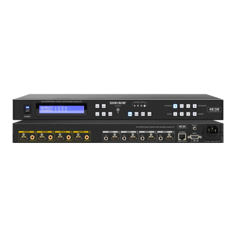
The SB-5684K is a professional 8x4 matrix routing switch.
Supporting (8) HDMI Inputs and (4) HDMI outputs with (1)
Preview output. The SB-5684K is based on HDMI standards and
supports full resolution HDMI video with (7) embedded EDID
so there is no signal degradation. High Denition digital signals
can be selected and distributed from any of the (8) Inputs to the
(4) Outputs +(1) Preview Output. The switcher is fully CEC and
HDCP 1.3 certied with HDMI 1.4a, 4K2K@30Hz, DVI 1.0, 3D
formats. Wide frequency range of 25MHz~340 MHz for full HD
and supports UXGA/WUXGA/DVI 1920x1200 resolutions to any
HD display. The SB-5684K has (1) HDMI connector per Input,
effectively making this an (8) In by (4+1) Out switcher. The EDID
management can be selected between (7) different modes.
Control is provided via front panel push buttons, IR remote, RS-
232 or TCP/IP (not a web-browser). A RS-232 Windows GUI
interface is provided for matrix routing control (Windows only).
1
4K2K HDMI MATRIX SWITCHER SERIES
Thank you for purchasing the SB-5684K 4K2K HDMI Matrix Routing Switch. You will nd this unit easy to install and highly
reliable but it is essential that you read this manual thoroughly before attempting to use the 8x4 4K2K HDMI matrix switcher.
TABLE OF CONTENTS
SAFETY PRECAUTIONS
Please read all instructions before attempting to unpack, install or
operate this equipment and before connecting the power supply.
Please keep the following in mind as you unpack and install this
equipment:
• Always follow basic safety precautions to reduce the risk of re,
electrical shock and injury to persons.
• To prevent re or shock hazard, do not expose the unit to rain,
moisture or install this product near water.
• Never spill liquid of any kind on or into this product.
• Never push an object of any kind into this product through any
openings or empty slots in the unit, as you may damage parts
inside the unit.
• Do not attach the power supply cabling to building surfaces.
• Use only the supplied power supply unit (PSU). Do not use the
PSU if it is damaged.
• Do not allow anything to rest on the power cabling or allow any
weight to be placed upon it or any person walk on it.
• To protect the unit from overheating, do not block any vents or
openings in the unit housing that provide ventilation and allow for
sufcient space for air to circulate around the unit.
DISCLAIMERS
The information in this manual has been carefully checked and
is believed to be accurate. We assume no responsibility for any
infringements of patents or other rights of third parties which may
result from its use.
We assume no responsibility for any inaccuracies that may be
contained in this document. We make no commitment to update
or to keep current the information contained in this document.
We reserve the right to make improvements to this document
and/or product at any time and without notice.
COPYRIGHT NOTICE
No part of this document may be reproduced, transmitted,
transcribed, stored in a retrieval system, or any of its part translated
into any language or computer le, in any form or by any means
— electronic, mechanical, magnetic, optical, chemical, manual,
or otherwise — without express written permission and consent.
© Copyright 2016. All Rights Reserved.
Version 1.2 JULY 2016
5684K-20150822-002
TRADEMARK ACKNOWLEDGMENTS
All products or service names mentioned in this document may
be trademarks of the companies with which they are associated.
IMPORTANT WARRANTY INFORMATION.
If you remove the HDMI screw posts, you must use the
provided HDMI Locking Post replacement screws to keep
the internal HDMI jack secure. Removing the HDMI screws
without installing the HDMI Locking Post replacement
screws will void your warranty.
LOOK A PUPPY!! NOW READ THIS!!

