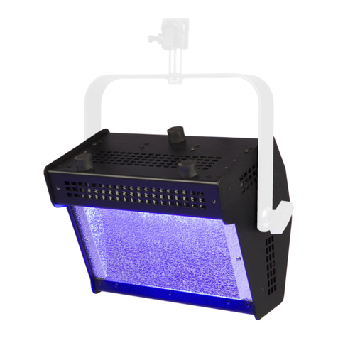
Altman Spectra CYC UV 50 Guide

Altman Lighting
Service & Parts Manual
Spectra CYC UV 50
Spectra CYC UV 100
Spectra CYC 50
Spectra CYC 100
Spectra CYC 200
Spectra CYC 400

Have a question regarding this manual?
The material in this manual is for information purposes only and is subject to change without notice. Altman Light-
ing assumes no responsibility for any errors or omissions which may appear in this manual.
Should you nd an error, have a suggestion or question regarding your Altman Lighting product, we would love to
hear from you.
You can reach us at:
Altman Lighting
57 Alexander Street
Yonkers, New York 10701
1.914.476.7987 (Main)
1.914.963.7304 (Fax)
www.altmanlighting.com
Note: Information contained in this document may not be duplicated in full or in part by any person without prior
written approval of Altman Lighting. Its sole purpose is to provide the user with conceptual information on the
equipment mentioned. The use of this document for all other purposes is specically prohibited.
The material in this manual is for information purposes only and is subject to change without notice. Altman
Lighting assumes no responsibility for any errors or omissions which may appear in this manual. For comments
and suggestions regarding corrections and/or updates to this manual, please visit the Altman Lighting web site at
El contenido de este manual es solamente para información y está sujeto a cambios sin previo aviso. Altman
Lighting con no asume responsabilidad por errores o omisiones que puedan aparecer. Cualquier comentario,
sugerencia o corrección con respecto a este manual, favor de dirijirlo a la ocina de Altman Lighting más cercana.
Der Inhalt dieses Handbuches ist nur für Informationszwecke gedacht, Aenderungen sind vorbehalten. Altman
Lighting uebernimmt keine Verantwortung für Fehler oder Irrtuemer, die in diesem Handbuch auftreten. FürBe-
merkungen und Verbesserungsvorschlaege oder Vorschlaege in Bezug auf Korrekturen und/oder Aktualisierun-
gen in diesem Handbuch, moechten wir Sie bitten, Kontakt mit der naechsten Altman Lighting Niederlassung
aufzunehmen.
Our Commitment
Altman Lighting continually engages in research related to product improvement. New materials, production
methods and design renements are introduced into existing products without notice as a routine expression of
the philosophy. For this reason any current Altman Lighting product may dier in some respect from its published
description, but will always equal or exceed the original design specications unless otherwise noted.
Document Number: (Rev. C)
Version as of: 12 December 2019
Spectra Series LED CYC Luminaires Service Manual
©2020 Altman Lighting. All rights reserved.

Spectra Cyc LED LuminairesService Manual
1
Important Information
Product Safety Notices
When using electrical equipment, basic safety precautions should always be followed including the
following:
a. READ AND FOLLOW ALL SAFETY INSTRUCTIONS.
b. Do not use outdoors unless the product is specied to operate in outdoor environments.
c. Do not mount near gas or electric heaters.
d. Equipment should be mounted in locations and at heights where it will not readily be subjected to
tampering by unauthorized personnel.
e. The use of accessory equipment not recommended by the manufacturer may cause an unsafe
condition.
f. Do not use this equipment for other than intended use.
g. Refer service to qualied personnel.
SAVE THIS MANUAL FOR FUTURE REFERENCE.
WARNINGS
WARNING: You must have access to a main circuit breaker or other power disconnect device
before installing any wiring. Be sure that power is disconnected by removing fuses or turning the
main circuit breaker o before installation. Installing the device with power on may expose you to
dangerous voltages and damage the device. A qualied electrician must perform this installation.
WARNING: Refer to National Electrical Code® and local codes for cable specications. Failure to
use proper cable can result in damage to equipment or danger to personnel.
WARNING: This equipment is intended for installation in accordance with the National Electric
Code® and local regulations. It is also intended for installation in indoor applications only. Before
any electrical work is performed, disconnect power at the circuit breaker or remove the fuse to
avoid shock or damage to the control. It is recommended that a qualied electrician perform this
installation.
WARNING: This Lighting Fixture IS NOT for residential installation or use.
THIS PRODUCT MUST BE INSTALLED IN ACCORDANCE WITH THE APPLICABLE INSTALLATION
CODE BY:
A PERSON FAMILIAR WITH THE CONSTRUCTION AND OPERATION OF THE PRODUCT AND THE
HAZARDS INVOLVED.
CE PRODUIT DOIT ÊTRE INSTALLÉ SELON LE CODE D’INSTALLATION PERTINENT, PAR UNE
PERSONNE

Spectra Cyc LED LuminairesService Manual
2
FCC Notice
This equipment has been tested and found to comply with the limits for a Class A digital device, pursuant
to part 15 of the FCC Rules. These limits are designed to provide reasonable protection against harmful in-
terference when the equipment is operated in a commercial environment. This equipment generates, uses,
and can radiate radio frequency energy and, if not installed and used in accordance with the instruction
manual, may cause harmful interference to radio communications.
Operation of this equipment in a residential area is likely to cause harmful interference in which case the
user will be required to correct the interference at his own expense.
Altman Lighting Product Warranty
Warranty Term
Altman Lighting, Inc., a subsidiary of Altman Stage Lighting Company, Inc., herein referred to as Altman,
warrants each new product (except for spare parts or products Altman does not manufacture) for a period
of TWO (2) years from date of shipment to correct by repair or replacement any part defect due to faulty
material or workmanship. Under these same terms products with an LED light source shall be warranted for
a period of THREE (3) years.
Altman warrants for NINETY (90) days any spare part it manufactures. On spare parts or products Altman
does not manufacture, including, but not limited to, lamps, sockets, lenses, roundels, electronics, ignitors,
ballasts, etc.; Altman will grant the same warranty given Altman by its vendors.
Altman assumes no responsibility for damage or faulty performance caused by misuse, improper installa-
tion, careless handling or where repairs have been attempted by others.
This warranty is in lieu of all warranties or guarantees expressed or implied and no representative or person
is authorized to assume Altman any other liability with the sale of Altman’s products.
For complete warranty terms and conditions, please refer to our web site at www.altmanlighting.com.
Warranty Service
In order to request warranty service, you must receive a Return Material Authorization (RMA) number prior
to return.
Return shipments must be visibly marked with the RMA number; the product must be returned (shipping
prepaid) to the factory at:
Altman Lighting Inc.
Attention: RMA # ___________
57 Alexander Street
Yonkers, NY 10701
The return must be within THIRTY (45) days of receiving the RMA from Altman.

3
Spectra Cyc LED Luminaires Service Manual
Important Information
Product Safety Notices ....................................................................................................................................................................1
WARNINGS........................................................................................................................................................................................1
FCC Notice
Altman Lighting Product Warranty .................................................................................................................................................2
Table of Contents
About This Manual
Product Descriptions .......................................................................................................................................................................5
Spectra Series CYC Optional Accessories ....................................................................................................................................5
Spectra Series CYC Other Accessories .........................................................................................................................................5
Features
Spectra Series CYC Standard Features..........................................................................................................................................6
Spectra Series CYC Specic Features ...........................................................................................................................................6
Spectra Series CYC Weight and Dimension .................................................................................................................................6
Troubleshooting
Troubleshooting Guide ....................................................................................................................................................................7
Maintenance Procedure
How to Disassemble a Spectra Series CYC Fixture ......................................................................................................................8
How to Replace the LED Board on a Spectra Series CYC Fixture...............................................................................................9
How to Replace the LED Driver Card on a Spectra Series CYC Fixture....................................................................................10
How to Replace the LED Processor on a Spectra Series CYC Fixture......................................................................................11
How to Replace the Power Supply on a Spectra Series CYC Fixture........................................................................................12
Firmware Update Procedure on a Spectra Series CYC Fixture..................................................................................................13
Manual Calibration Procedure on a Spectra Series CYC Fixture...............................................................................................14
Manual Calibration Procedure on a Spectra Series CYC Fixture...............................................................................................15
Spare Parts......................................................................................................................................................................................16
Hardware Description.....................................................................................................................................................................16
Wiring Diagram
Spectra Cyc 50................................................................................................................................................................................17
Spectra Cyc 100..............................................................................................................................................................................17
Spectra Cyc 200..............................................................................................................................................................................18
Spectra Cyc 400..............................................................................................................................................................................19
Wire Harness
54-5420 - Spectra Cyc Wire Harness C – DMX In to Processor .................................................................................................20
54-5425 - Spectra Cyc Wire Harness – DMX Out to Processor ..................................................................................................20
54-5435 - Wire Harness F – Ribbon Cable Driver to Light Engine .............................................................................................20
Schematics
61-0465 - LED Driver Board Schematics ......................................................................................................................................21
61-0465 - LED Driver Board BOM..................................................................................................................................................22
61-0510 - LED Driver Board Schematics ......................................................................................................................................23
61-0510 - LED Driver Board BOM..................................................................................................................................................24
61-0460 - LED Driver Board Schematics ......................................................................................................................................25
61-0460 - LED Driver Board BOM..................................................................................................................................................26
61-0455 - LED Driver Board Schematics ......................................................................................................................................27
61-0455-25 - LED Driver Board BOM - RGBA Board....................................................................................................................28
61-0455-30 - LED Driver Board BOM - RGBW Board...................................................................................................................28
61-0455-40 - LED Driver Board BOM - 6K Board..........................................................................................................................28
61-0455-50 - LED Driver Board BOM - 3K / 6K Board..................................................................................................................28
61-0600 - LED Driver Board Schematics ......................................................................................................................................29
61-0600-25 - LED Driver Board BOM - RGBA Board....................................................................................................................29
61-0600-30 - LED Driver Board BOM - RGBW Board...................................................................................................................30
61-0600-35 - LED Driver Board BOM - 3K White Board...............................................................................................................30
61-0600-36 - LED Driver Board BOM - 6K White Board...............................................................................................................30
61-0600-50 - LED Driver Board BOM - 3K / 6K White Board .......................................................................................................30
61-0621-25 - LED Driver Board Schematics .................................................................................................................................31
61-0621-25 - LED Driver Board BOM - UV Board .........................................................................................................................31
Table of Contents

Spectra Cyc LED LuminairesService Manual
4
Drawing Assembly
Spectra CYC 50 Main Assembly....................................................................................................................................................32
Spectra CYC 50 Front Assembly...................................................................................................................................................33
Spectra CYC 50 Rear Assembly ....................................................................................................................................................34
Spectra CYC 100 Main Assembly..................................................................................................................................................35
Spectra CYC 100 Front Assembly.................................................................................................................................................36
Spectra CYC 100 Rear Assembly ..................................................................................................................................................37
Spectra CYC 200 Main Assembly..................................................................................................................................................38
Spectra CYC 200 Front Assembly.................................................................................................................................................39
Spectra CYC 200 Rear Assembly ..................................................................................................................................................40
Spectra CYC 400 Main Assembly..................................................................................................................................................41
Spectra CYC 400 Front Assembly.................................................................................................................................................42
Spectra CYC 400 Rear Assembly ..................................................................................................................................................43

5
Spectra Cyc LED Luminaires Service Manual
About This Manual
The document provides service instructions for the following products:
• Spectra Series Cyc Luminaires
Please read all instructions before installing or using this product. Retain this manual for future
Product Descriptions
Spectra Series CYC Optional Accessories
Spectra Series CYC Other Accessories
Part Number Description
SSCYCUV50-* Spectra Cyc UV 50
SSCYC50-* Spectra Cyc 50
SSCYC100-UV-* Spectra Cyc UV 100
SSCYC100-* Spectra Cyc 100
SSCYC200-* Spectra Cyc 200
SSCYC400-* Spectra Cyc 400
Part Number Description
SC-36-BK Safety Cable
510 Malleable Iron Pipe Clamp
FT Floor Trunnion Pair
SSCYC**-YOKE* Spectra Cyc Yoke Hardware for 1 Fixture (includes C-Clamp)
*Specify color at time of ordering by adding the following code for color: B = Black or W = White.
** Specify Model at time of ordering
Part Number Description
SS-CYC-**-CF-* Spectra Series LED Cyc Color Frame (Note: Only available for the 50 and 100)
SS-CYC-LINK-* Spectra Series LED Cyc Link Plates
SS-CYC-SHIELD-* Spectra Series LED Cyc Safety Shield
99-DMX-TERM In Line 5 Pin DMX Terminator
*Specify color at time of ordering by adding the following code for color: B = Black or W = White.
** Specify Model at time of ordering

Spectra Cyc LED LuminairesService Manual
6
Features
Spectra Series CYC Standard Features
• Available in 5 Standard LED color congurations: RGBA, RGBW, 3K White, 6K White, or 3K-6K Tun-
able White
Note: The RGBW version utilizes 3K emitters for the white channel. Variants will be considered cus-
tom.
• Asymmetrical reector designed for broad, even distribution
• Patented LED blending lens
• On-board multi-voltage power supply 100-240VAC.
• Feed through power and data capabilities using PowerCON and 5-pin XLR connectors.
• Compatible with DMX and RDM protocols
• Push button addressing
• Preprogrammed modes for xed colors, timed color changes and strobes.
• Integrated carrying handle
• Convection cooled, no fans
• cETLus listed for indoor use and CE marked
• Made in the USA
Spectra Series CYC Specic Features
Spectra CYC UV 50 and UV 100
• Uses 365nm UV LEDs
Spectra Series CYC Weight and Dimension
Model Number Lenght Width Height Weight *
Spectra Cyc UV 50 7.18 in /
182.4 mm
6.84 in /
173.7 mm
8.28 in /
210.3 mm
7 lbs /
3.2 kg
Spectra Cyc 50 7.18 in /
182.4 mm
6.84 in /
173.7 mm
8.28 in /
210.3 mm
7 lbs /
3.2 kg
Spectra Cyc UV 100 11.65 in /
295.9 mm
7.45 in /
189.2 mm
11.2 in /
284.5 mm
11 lbs /
5.0 kg
Spectra Cyc 100 11.65 in /
295.9 mm
7.45 in /
189.2 mm
11.2 in /
284.5 mm
11 lbs /
5.0 kg
Spectra Cyc 200 23.25 in /
590.6 mm
7.45 in /
189.2 mm
10.58 in /
268.7 mm
18 lbs /
8.2 kg
Spectra Cyc 400 46.24 in /
1174.5 mm
7.45 in /
189.2 mm
10.58 in /
268.7 mm
37 lbs /
16.8 kg

7
Spectra Cyc LED Luminaires Service Manual
Troubleshooting
Troubleshooting Guide
The chart below provides possible causes and remedies for various error messages and/or symptoms. If this
chart is unable to address your issue, please contact your authorized dealer or Altman technical supprot at
1.914.476.7987 or [email protected] for assistance.
Description Symptom Possible Cause/ Remedy
No Light Output Fixture will not produce or output
light and connected to power or
dmx
- Check DMX Mode matches
Console settings.
- See if unit works in Stand Alone
Mode
Low Light Output Fixture produces low light output
and connected to power.
- Check the unit in Stand Alone
mode.
- Try swapping LED Driver Cards
- If possible swap LED board
No Power at Luminaire Luminaire does not power up - Circuit not energized...
- Power cable wired incorrectly...
- If everything above is correct,
then the issue could be a bad
power supply
DMX Data Control. Fixture will not respond to DMX
commands.
- Make sure the unit is in DMX
mode not Stand Alone Mode.
- A Green dot will light up on the
LCD to show that the unit see DMX
- Check DMX Mode matches Con-
sole Patch settings.
LCD Screen Buttons do respond Fixture will power up but will not
respond to button press.
Try Prowering down the xture and
wait a few seconds
Check to see if Enabling Master
Control Mode is o
Check to see if Lock Mode is
disabled

Spectra Cyc LED LuminairesService Manual
8
Maintenance Procedure
How to Disassemble a Spectra Series CYC Fixture
Note: The following will show you how to take a SSCYC100 apart but the same can be done for the 50, 200 and 400
units.
The following Tools will be needed to complete this task
1 x Phillips Head Screwdriver
DANGER: Before beginning procedure BE SURE AC LINE POWER IS DISCONNECTED.
The following steps will walk you thru how to disassemble a Spectra CYC
Remove the 6 screws that hold on the left and right-side plates. Figure 1
Flip the unit upside down and remove the screws that hold the Rear Assembly to the Front Assembly.
Figure 2
Flip the unit back over and remove the screws on the top of the unit that hold the reector to the rear
assembly. Figure 3
The Rear Assembly and Front assembly should be free to move now. To take them apart you will slide
the bottom end out rst, then pull the front assembly down and out. Figure 4.1 thru 4.3.
You will follow the same steps in reverse order to reassemble the unit back together.
1.
2.
3.
4.
5.
Note: There is a ribbon cable that attaches between the Front and Rear Assembly that needs to be unplugged before
each section can be completely disassemble
Figure 1 Figure 2 Figure 3
Figure 4.1 Figure 4.2 Figure 4.3

9
Spectra Cyc LED Luminaires Service Manual
Maintenance Procedure
How to Replace the LED Board on a Spectra Series CYC Fixture
Note: The following will show you how to take a SSCYC100 apart but the same can be done for the 50, 200 and 400
units.
The following Tools will be needed to complete this task
1 x Phillips Head Screwdriver
DANGER: Before beginning procedure BE SURE AC LINE POWER IS DISCONNECTED.
The following steps will walk you thru how to repalce the LED Board on a Spectra Series CYC.
Get access to the Front Assembly of the Spectra Cyc. Figure 1
Follow the steps on page 8 on how to Disassemble a Spectra CYC Fixture.
Next you will remove the screws that are on the bottom base that hold the led board, reector and heat sink to the
Front Assembly. Figure 2
Unscrew the two screws that are holding the lens to reector. Once the lens has been removed the reector and
its supports will be free to move as well. Figure 3
Next you will remove the 61-0470 insulator that lays between the reector and led board. Figure 4
After the screws are removed you will follow the same steps in reserve order to put the led board back on.
Next you will unscrew the 5 screws holding in the led board to the heat sink. After that the led board will be free to
come o the heat sink. Figure 5
1.
2.
3.
4.
5.
6.
Figure 1 Figure 2 Figure 3
Figure 4 Figure 5

Spectra Cyc LED LuminairesService Manual
10
Maintenance Procedure
How to Replace the LED Driver Card on a Spectra Series CYC Fixture
Note: The following will show you how to take a SSCYC100 apart but the same can be done for the 50, 200 and 400
units.
The following Tools will be needed to complete this task
1 x Phillips Head Screwdriver
DANGER: Before beginning procedure BE SURE AC LINE POWER IS DISCONNECTED.
The following steps will walk you thru how to replace the LED Driver Card on a Spectra CYC.
Get access to the Rear Assembly of the Spectra Cyc.
Follow the steps on page 8 on how to Disassemble a Spectra CYC Fixture.
Unplug the 54-5435 Processor to Driver Harness as well as the 54-5915 P/S to Driver Harness. Figure 1
Unscrew the 4 screws holding in the driver board to the LED Processor Board. Figure 2
Once the screws have been removed, the board should be free to come out.
You will follow the same steps in reserve order to install the LED Driver Board
1.
2.
3.
4.
5.
54-5430 - Processor to Driver
Wire Harness
54-5915 - P/S to Driver Wire
Harness
Figure 1 Figure 2

11
Spectra Cyc LED Luminaires Service Manual
Maintenance Procedure
How to Replace the LED Processor on a Spectra Series CYC Fixture
Note: The following will show you how to take a SSCYC100 apart but the same can be done for the 50, 200 and 400
units.
The following Tools will be needed to complete this task
1 x Phillips Head Screwdriver
1 x 3/16 Nut Driver
DANGER: Before beginning procedure BE SURE AC LINE POWER IS DISCONNECTED.
The following steps will walk you thru how to replace the LED Processor Card on a Spectra CYC.
Get access to the Rear Assembly of the Spectra Cyc.
Follow the steps on page 8 on how to Disassemble a Spectra CYC Fixture.
Unplug the 54-5435 Processor to Driver Harness as well as the 54-5915 P/S to Driver Harness. Figure 1
Unscrew the 4 screws holding in the driver board to the LED Driver Board.
Once the standos have been removed, the board should be free to come out.
You will follow the same steps in reserve order to install the LED Processor Board
1.
2.
3.
6.
7.
Unplug the 54-5425 DMX In and 54-5420 DMX Out Cables from the LED Processor Board. Figure 24.
Remove the 4 stand os with the 3/16 Nut Driver.5.
54-5430 - Processor to Driver
Wire Harness
54-5915 - P/S to Driver Wire
Harness
Figure 1 Figure 2

Spectra Cyc LED LuminairesService Manual
12
Maintenance Procedure
How to Replace the Power Supply on a Spectra Series CYC Fixture
Note: The following will show you how to take a SSCYC100 apart but the same can be done for the 50, 200 and 400
units.
The following Tools will be needed to complete this task
1 x Phillips Head Screwdriver
DANGER: Before beginning procedure BE SURE AC LINE POWER IS DISCONNECTED.
The following steps will walk you thru how to replace the LED Power Supply on a Spectra CYC.
Get access to the Rear Assembly of the Spectra Cyc.
Follow the steps on page 8 on how to Disassemble a Spectra CYC Fixture. Figure 1
Unplug the 54-5915 P/S to Driver Harness as well as the 54-3075 EMI Filter to P/S Harness. Figure 2
Unscrew the 4 screws holding the Power Supply to the Rear Assembly. Figure 3
Once the screws have been removed, the power supply should be free to come out of the unit. Figure 4
1.
2.
3.
4.
You will follow the same steps in reserve order to install the Power Supply5.
54-5915 -
LED Driver to P/S
54-3075 -
EMI Filter to P/S Harness
Figure 1 Figure 2
Figure 3 Figure 4

13
Spectra Cyc LED Luminaires Service Manual
Maintenance Procedure
Firmware Update Procedure on a Spectra Series CYC Fixture
The following Tools will be needed to complete this task
1 x Phillips Head Screwdriver
1 x PICKit3
DANGER: Before beginning procedure BE SURE AC LINE POWER IS DISCONNECTED.
The following steps will walk you thru how to Update Firmware to a Spectra CYC.
Get access to the Rear Assembly of the Spectra Cyc.
Follow the steps on page 8 on how to Disassemble a Spectra CYC Fixture.
Carefully separate the driver board (61-0465) from the processor board (61-0460), keeping the wires connected
1.
2.
Remove the 4 screws holding the 61-0465 Driver board to the Rear Assembly. Figure 1
Carefully set the unit sideways with Driver and Processor Boards near the bottom, and set Driver board on bench
with paper to insulate it from any metal parts. Figure 2
Plug PICKit3 and adapter into J1 of Processor board (61-0460)
Connect USB power to PICKit3 and energize
On PICKit3, after it boots up:
“POWER” Light should be steady green,
“ACTIVE” Light should be ashing Blue,
“STATUS” Light should be o.
Turn Fixture On
Press black “PROGRAM” button on PICKit3.
While programming:
“POWER” Light should be steady green,
“ACTIVE” Light should be steady Blue,
“STATUS” Light should be ashing red.
When programming is completed:
“POWER” Light should be steady green,
“ACTIVE” Light should be ashing Blue,
“STATUS” Light should be steady green.
Disconnect AC Line power from Blue Powercon Connector. and unplug and then wait 30 seconds
Disconnect PICKit3 and adapter from J1 of processor board (61-0460).
TEST- Reconnect AC Line Power to Blue Powercon Connector and energize.
Verify on boot-up, that display on unit momentarily shows new software version.
Disconnect AC Line power from Blue Powercon Connector and unplug
Reassemble unit in reverse order.
3.
4.
5.
6.
7.
8.
9.
10.
11.
12.
13.
14.
15.
16.
Figure 2
Figure 1

Spectra Cyc LED LuminairesService Manual
14
Maintenance Procedure
Manual Calibration Procedure on a Spectra Series CYC Fixture
The following Tools will be needed to complete this task
1 x DMX Controller
Calibration mode requirements to be set prior to entering calibration mode:
The DMX address must be set to the desired address to be used during calibration. For example if two xtures will be
calibrated together set your rst xture to channel 1 and your second xture to channel 5. Note: 4 color 16 bit controls
will be used during calibration regardless of the personality selected in normal operation.
The xture must be in DMX mode not in any of the stand alone modes.
Pick one xture to use as a reference that you do not adjust, set it to 100% DMX level for the color being calibrated,
and you will adjust the other units to match it.
All units should be on the same amount of time in the same colors so that they are the same temperature. It’s best to
give xtures 3 hours of warm up time with all 4 channels on at 100%
This method sets all colors at once for white balance, so it is not as good as factory calibration method.
Entering calibration mode:
Hold the tens digit button while powering up the xture. The display will show “CAL”
When the button is released, the xture will be in calibration mode and the display will continue to show “CAL”
Setting High End Trim Values
Note: the xture will operate as if it is personality 5 (16 bit, no smoothing, no mastering). The DMX address
should be set prior to entering calibration mode. Also use a DMX console that provides a computer monitor.
A pocket console or two scene preset board will not provide the accuracy you will need.
It’s best to leave your rst xture (reference xture) in DMX mode not calibration mode.
On your DMX console label your channel faders to the correct LED array matching your channel numbers. For exam-
ple Channel 1 R, Channel 2 G, Channel 3 B, Channel 4 A. Repeating the pattern depending on the amount of xtures
you are calibrating.
Fixture 1 will be in DMX mode not calibration mode. Set your channel faders 1-4 to 100%.
Fixture 2 should be in CAL mode. Set your channel faders to 50%.
Normal balance is 50% slider level… you can adjust a little up or down from there. It is very important that the fader
levels do not go much higher than 50% as it is possible to over drive the LED’s. 100% fader levels in cal mode will
FRY them!!
Color combinations to calibrate for more color blending accuracy are…
a) Red and Blue – Adjust the blue and red intensities matching the reference
b) Red and Green – adjust the green intensity only as red has been matched to reference
c) Blue and Amber - adjust the amber intensity only as blue has been matched to reference
Contiune onto the Next Page...........
1.
2.
3.
4.
5.
1.
2.
1.
2.
3.
4.
5.

15
Spectra Cyc LED Luminaires Service Manual
Maintenance Procedure
Manual Calibration Procedure on a Spectra Series CYC Fixture
Note: Write down the specic intensity levels as your color matching for the unit that is being calibrated.
Then set all 4 channels to the levels you choose during color matching. Set your reference xture channels
to 100% and compare the two xtures making sure that white wash is matching. Make any additional ad-
justments if needed. It is not recommended to calibrate with all 4 channels on as color matching may not be
accurate.
Once you have selected your new calibration levels and all four channels are at their high trim levels press the ones
button on the xture to save calibration.
Turn the xture o and then back on again to resume normal operation with the new trim values.
Additional Notes:
-While in calibration mode, pressing the ones buttons will over-write the prior calibration values. After the values have
been set, you can re-record them while still in calibration mode. You do not need to exit and re-enter the calibration
mode. You can simply set the new values and re-record them any time.
-If you enter calibration mode and do not record new values, the old calibration values will remain in place after cy-
cling the power.
-Calibration mode bypasses the keyboard lock feature.
-Restore defaults bypasses the keyboard lock feature.
***IMPORTANT – Calibration mode ignores the temperature sensor.
***IMPORTANT – Attempting to enter calibration mode with the xture set up for a standalone function will
yield unpredictable results. Please make sure the xture is in DMX mode when powering the xture up to
enter calibration mode.
6.
7.

Spectra Cyc LED LuminairesService Manual
16
Spare Parts
Hardware Description
Part Number Description Purpose
37-0015 5/16-18 X 1-1/2 T-Handle Black T-Handle Black
38-0149 5/16-18 X 1-1/4L Rubber Bumper Feet
50-CINT1175A480 48V 120W 100-240V Input Power Supply
61-10DKAG5 EMI FILTER 115/250V 10A EMI Filter
60-0029 4A Ckt Breaker Circuit Breaker
61-0460-45 Processor Card with Display Processor Card
61-0465-45 LED Driver Board for RGBA/RGBW Driver Card
61-0510 LED Driver Board for 3K, 6K, and UV Fixtures Driver Card
61-0600-25 LED Board for RGBA Fixtures LED Card for Spectra Cyc 50
61-0600-30 LED Board for RGBW Fixtures LED Card for Spectra Cyc 50
61-0600-45 LED Board for 6K Fixtures LED Card for Spectra Cyc 50
61-0600-50 LED Board for 3K Fixtures LED Card for Spectra Cyc 50
61-0455-25 LED Board for RGBA Fixtures LED Card for Spectra Cyc 100, 200, 400
61-0455-30 LED Board for RGBW Fixtures LED Card for Spectra Cyc 100, 200, 400
61-0455-40 LED Board for 6K Fixtures LED Card for Spectra Cyc 100, 200, 400
61-0455-50 LED Board for 3K Fixtures LED Card for Spectra Cyc 100, 200, 400
61-0621-25 LED Board for UV Fixtures LED Card for Spectra Cyc 100, 200, 400
Part Number Description Purpose
30-FHP0606-BZ 6-32 x 3/8 Flat Head Phillips Screw
30-PHP0610 6-32 x 5/8 Pan Head Phillips Screw
30-PHP0606 6-32 x 3/8 Pan Head Phillips Screw
30-PHP0404 4-40 x 1/4 Pan Head Phillips Screw
30-PHP0406 4-40 x 3/8 Pan Head Phillips Screw
30-FHP0408-BZ 4-40 x 1/2 Flat Head Phillips Screw
30-FHP0412-BZ 4-40 x 3/4 Flat Head Phillips Screw
30-FHP0406-BZ 4-40 x 3/8 Flat Head Phillips Screw
32-FW500 1/2” Flat Washer STL ZP Washer
32-BF375 3/8” ID x 1/8” OD Cup Washer Washer
32-CW375-25 3/8” ID x 1-1/8” OD Cup Washer Washer
30-STQ50064 1/2-13 x 4” Square Head Set Bolt
31-HN06 6-32 Nylon Insert Locknut STL Nut
31-HN04 4-40 Nylon Insert Locknut STL Nut
26-RAF2065440A0 .187” HEX 1.00” Long x 4-40 Stando
26-RAF2053440A0 .187" HEX 1/4" Long x 4-40 Stando
26-RAF2057440A0 .187” HEX 1/2” Long x 4-40 Stando
51-NC5FDLB1 Panel Mount Conn XLR 5 Pin Female DMX Out Connector
51-NC5MDLB1 Panel Mount Conn XLR 5 Pin Male DMX In Cnnector
52-NAC3MPB-1 20A Neutrik PowerCON Panel Mount Power Out ( Grey)
52-NAC3MPA-1 20A Neutrik PowerCON Panel Mount Power In (Blue)

17
Spectra Cyc LED Luminaires Service Manual
Wiring Diagram
Spectra Cyc 50
Spectra Cyc 100
L
N
+
-
+
-
DMX
D +
D -
COM
IN
BOARD
RGBA DRIVER
61-0465
/DISPLAY
BOARD
PROCESSOR
61-0460
HEADER
RIBBON
20 COND
BOARD
61-0600-25
RGBA LED
10 COND
RIBBON
BROWN
BLUE
1
1
1
JUMPERS
DMX
COM
FLOAT
JUMPER
PROG PROGRAMMING
JP4
JP1
JP2
JP3
1
WIRE HARNESS: 54-5435
OUT
DMX
D -
COM
D +
1 1
J5 J4 J3
J2J3
J4
J1
J1
P1
1
50-LB115S24K
24 VOLT
POWER SUPPLY
WIRE #54-307518BR
COLOR: BROWN
18AWG
WIRE HARNESS: 54-5915
WIRE #54-3055100005
COLOR: YELLOW
18AWG
WIRE #54-3055100006
COLOR: BLUE
18AWG
POWER CON IN
PART#: 52-NAC3MPA-1
COLOR: BLUE
POWER CON OUT
PART#: 52-NAC3MPB-1
COLOR: GRAY
WIRE #54-101512YG
COLOR: GREEN WITH YELLOW
STRIPES
12AWG
WIRE #54-101512BR
COLOR:BROWN
12AWG
INPUT SUPPLY
XLR
MALE
5-PIN
XLR
FEMALE
5-PIN
2
3
1
4
5
D+
D-
COM
12
3
4
5
D+
COM
D-
DMX CABLE
PIN 1: DMX COMMON ( GREEN )
PIN 2: DATA - ( WHITE )
PIN 3: DATA + ( BLACK )
DMX PIN IN
DMX CABLE
WIRE HARNESS:54-5420
WIRE HARNESS::54-5425
OUT
DMX IN
DMX
PIN 1: DMX COMMON ( BROWN )
PIN 2: DATA - ( RED )
PIN 3: DATA + ( ORANGE )
DMX PIN OUT
LN
G
WIRE HARNESS: 54-5430
N
G
L
61-28A2029-0A0
FERRITE CLAMP ON
61-10DKAG5
EMI FILTER
WIRE #54-101512BL
COLOR: SOLID BLUE
12AWG
WIRE #54-307518BL
COLOR: BLUE
18AWG

Spectra Cyc LED LuminairesService Manual
18
Wiring Diagram
Spectra Cyc 200
This manual suits for next models
5
Table of contents
Other Altman Light Fixture manuals
Popular Light Fixture manuals by other brands

Claypaky
Claypaky SHARPY PLUS instruction manual

HAMPTON BAY
HAMPTON BAY SKU 185-632 instruction manual

FormaLighting
FormaLighting MOTO-ZERO COMPASSO 40 Installation instruction

Claypaky
Claypaky IGLOO WL-C61199 instruction manual

Show Tec
Show Tec EventSpot 1600 Q4 manual

Desisti
Desisti SOFT LED 4 instruction manual